Table of Contents
Advertisement
Quick Links
UG509: BG22 Explorer Kit User's Guide
The BG22 Explorer Kit is an ultra-low cost, small form factor devel-
opment and evaluation platform for the EFR32BG22 Wireless
Gecko System-on-Chip.
The BG22 Explorer Kit is focused on rapid prototyping and concept creation of IoT appli-
cations. It is designed around the EFR32BG22 SoC, which is an ideal device family for
developing energy-friendly connected IoT applications.
The kit features a USB interface, an on-board SEGGER J-Link debugger, one user-LED
and button, and support for hardware add-on boards via a mikroBus socket and a Qwiic
connector. The hardware add-on support allows developers to create and prototype ap-
plications using a virtually endless combination of off-the-shelf boards from mikroE,
sparkfun, AdaFruit, and Seeed Studios.
silabs.com | Building a more connected world.
Copyright © 2021 by Silicon Laboratories
TARGET DEVICE
• EFR32BG22 Wireless Gecko System-on-
Chip (EFR32BG22C224F512IM40)
• High performance 2.4 GHz radio
• 32-bit ARM® Cortex®-M33 with 76.8 MHz
maximum operating frequency
• 512 kB flash and 32 kB RAM
KIT FEATURES
• User LED and push button
• 20-pin 2.54 mm breakout pads
• mikroBUS™ socket
• Qwiic® connector
• SEGGER J-Link on-board debugger
• Virtual COM port
• Packet Trace Interface (PTI)
• USB-powered
SOFTWARE SUPPORT
• Simplicity Studio™
ORDERING INFORMATION
• BG22-EK4108A
Rev. 1.1
Advertisement
Table of Contents

Related Manuals for Silicon Laboratories BG22 Explorer Kit


Summary of Contents for Silicon Laboratories BG22 Explorer Kit
- Page 1 • EFR32BG22 Wireless Gecko System-on- Chip (EFR32BG22C224F512IM40) The BG22 Explorer Kit is focused on rapid prototyping and concept creation of IoT appli- • High performance 2.4 GHz radio cations. It is designed around the EFR32BG22 SoC, which is an ideal device family for •...
-
Page 2: Table Of Contents
Table of Contents 1. Introduction ....... . 4 1.1 Kit Contents ....... 4 1.2 Getting Started . - Page 3 5.5.1 Recommendations for 2.4 GHz ETSI EN 300-328 Compliance ... .22 5.5.2 Recommendations for 2.4 GHz FCC 15.247 Compliance ....22 6.
-
Page 4: Introduction
Programming the BG22 Explorer Kit is easily done using a USB Micro-B cable and the on-board J-Link debugger. A USB virtual COM port provides a serial connection to the target application, and the Packet Trace Interface (PTI) offers invaluable debug information about transmitted and received packets in wireless links. -
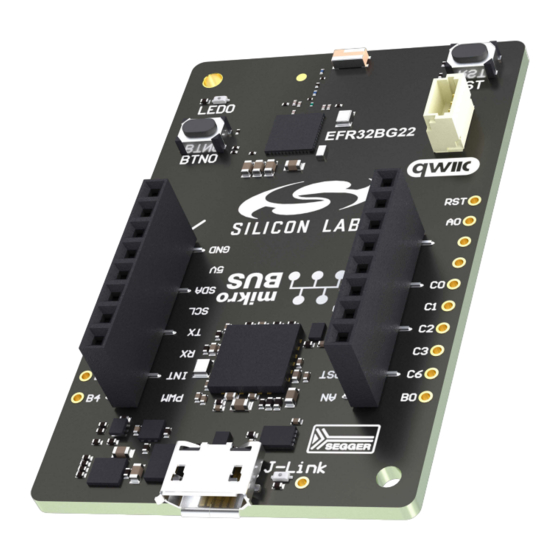
Page 5: Kit Hardware Layout
UG509: BG22 Explorer Kit User's Guide Introduction 1.4 Kit Hardware Layout BG22 Explorer Kit layout is shown below. 35.6 mm 2.4 GHz EFR32BG22 Chip Antenna Wireless Gecko Top View Reset Button Push Button Qwiic Connector Breakout Pads 55.9 mm On-board USB... -
Page 6: Specifications
UG509: BG22 Explorer Kit User's Guide Specifications 2. Specifications 2.1 Recommended Operating Conditions Parameter Symbol Unit USB Supply Input Voltage – +5.0 – Supply Input Voltage (VMCU supplied externally) +3.3 VMCU Operating Temperature – – ˚C Note: The typical supply voltage to the EFR32BG22 is 3.0 V, but the maximum voltage is a function of temperature and average life- time current load. -
Page 7: Hardware
UG509: BG22 Explorer Kit User's Guide Hardware 3. Hardware The core of the BG22 Explorer Kit is the EFR32BG22 Wireless Gecko System-on-Chip. Refer to section 1.4 Kit Hardware Layout placement and layout of the hardware components. 3.1 Block Diagram An overview of the BG22 Explorer Kit is illustrated in the figure below. -
Page 8: Power Supply
Wireless SoC Peripherals Figure 3.2. BG22 Explorer Kit Power Topology The 5 V power net on the USB bus is regulated down to 3.3 V using an low-dropout regulator (LDO). An automatic isolation circuit isolates the LDO when the USB cable is not plugged in. -
Page 9: On-Board Debugger
3.5 On-board Debugger The BG22 Explorer Kit contains a microcontroller separate from the EFR32BG22 Wireless Gecko that provides the user with an on- board J-Link debugger through the USB Micro-B port. This microcontroller is referred to as the "on-board debugger", and is not pro- grammable by the user. -
Page 10: Connectors
3.6 Connectors The BG22 Explorer Kit features a USB Micro-B connector, 20 breakout pads, a mikroBUS connector for connecting mikroBUS add-on boards, and a Qwiic connector for connecting Qwiic Connect System hardware. The connectors are placed on the top side of the board, and their placement and pinout are shown in the figure below. -
Page 11: Breakout Pads
The pin-routing on the Wireless Gecko is very flexible, so most peripherals can be routed to any pin. However, pins may be shared between the breakout pads and other functions on the BG22 Explorer Kit. The table below includes an overview of the breakout pads and functionality that is shared with the kit. -
Page 12: Mikrobus Socket
Qwiic connector, and all mikroBUS signals are also routed to adjacent breakout pads. When inserting a mikroBUS add-on board, refer to the orientation notch on the BG22 Explorer Kit, shown in the figure below, to ensure correct orientation. -
Page 13: Qwiic Connector
The BG22 Explorer Kit features a Qwiic connector compatible with Qwiic Connect System hardware. The Qwiic connector provides an easy way to expand the functionality of the BG22 Explorer Kit with sensors, LCDs, and other peripherals over the I C interface. The Qwiic connector is a 4-pin polarized JST connector, which ensures the cable is inserted the right way. -
Page 14: Debugging
4. Debugging The BG22 Explorer Kit contains an on-board SEGGER J-Link Debugger that interfaces to the target EFR32BG22 using the Serial Wire Debug (SWD) interface. The debugger allows the user to download code and debug applications running in the target EFR32BG22. -
Page 15: Radio
UG509: BG22 Explorer Kit User's Guide Radio 5. Radio 5.1 RF Section This section gives a short introduction to the RF section of the BRD4108A board. The schematic of the RF section is shown in the figure below. High 2.4 GHz... -
Page 16: Rf Matching Bill Of Materials
UG509: BG22 Explorer Kit User's Guide Radio 5.1.3 RF Matching Bill of Materials The BRD4108A RF matching network bill of materials is shown in the following table. Table 5.1. BRD4108A RF Matching Network Bill of Materials Component name Value Manufacturer Part Number 2.7 nH... -
Page 17: Antenna Matching Bill Of Materials
UG509: BG22 Explorer Kit User's Guide Radio 5.1.5 Antenna Matching Bill of Materials The BRD4108A antenna matching network bill of materials is shown in the following table. Table 5.2. BRD4108A Antenna Matching Network Bill of Materials Component name Value Manufacturer... -
Page 18: Relaxation With Modulated Carrier
UG509: BG22 Explorer Kit User's Guide Radio 5.3 Relaxation with Modulated Carrier Depending on the applied modulation scheme and the Spectrum Analyzer settings specified by the relevant EMC regulations, the measured power levels are usually lower compared to the results with unmodulated carrier. These differences have been measured and used as relaxation factors on the results of the radiated measurement performed with unmodulated carrier. -
Page 19: Maximum Radiated Power Measurement
UG509: BG22 Explorer Kit User's Guide Radio 5.4.1 Maximum Radiated Power Measurement The transceiver was operated in unmodulated carrier transmission mode and the output power of the radio was set to 6 dBm. The re- sults are shown in the table below. -
Page 20: Antenna Pattern Measurement
UG509: BG22 Explorer Kit User's Guide Radio 5.4.2 Antenna Pattern Measurement The measured typical antenna patterns are shown in the figures below. Normalized Radiation Pattern [dB], XY cut 0° 315° 45° 270° 90° 225° 135° Horizontal 180° Vertical Figure 5.4. Antenna Pattern - XY silabs.com | Building a more connected world. - Page 21 UG509: BG22 Explorer Kit User's Guide Radio Normalized Radiation Pattern [dB], XZ cut 0° 315° 45° 270° 90° 225° 135° Horizontal 180° Vertical Figure 5.5. Antenna Pattern - XZ silabs.com | Building a more connected world. Rev. 1.1 | 21...
-
Page 22: Emc Compliance Recommendations
UG509: BG22 Explorer Kit User's Guide Radio Normalized Radiation Pattern [dB], YZ cut 0° 315° 45° 270° 90° 225° 135° Horizontal 180° Vertical Figure 5.6. Antenna Pattern - YZ 5.5 EMC Compliance Recommendations 5.5.1 Recommendations for 2.4 GHz ETSI EN 300-328 Compliance As it was shown in the previous chapter, with the EFR32BG22 output power set to 6 dBm, the radiated power of the fundamental of the BRD4108A complies with the 20 dBm limit of the ETSI EN 300-328. -
Page 23: Schematics, Assembly Drawings, And Bom
UG509: BG22 Explorer Kit User's Guide Schematics, Assembly Drawings, and BOM 6. Schematics, Assembly Drawings, and BOM Schematics, assembly drawings, and bill of materials (BOM) are available through Simplicity Studio when the kit documentation pack- age has been installed. They are also available from the kit page on the Silicon Labs website: http://www.silabs.com/. -
Page 24: Kit Revision History And Errata
UG509: BG22 Explorer Kit User's Guide Kit Revision History and Errata 7. Kit Revision History and Errata 7.1 Revision History The kit revision can be found printed on the box label of the kit, as outlined in the figure below. The kit revision history is summarized in the table below. -
Page 25: Board Revision History And Errata
UG509: BG22 Explorer Kit User's Guide Board Revision History and Errata 8. Board Revision History and Errata 8.1 Revision History The board revision can be found laser printed on the board, and the board revision history is summarized in the following table. -
Page 26: Document Revision History
UG509: BG22 Explorer Kit User's Guide Document Revision History 9. Document Revision History Revision 1.1 October 2021 • Updated terminology in Table 3.2 in accordance with the Silicon Labs Lexicon Project. Revision 1.0 September 2021 • Initial document release. silabs.com | Building a more connected world. - Page 27 Note: This content may contain offensive terminology that is now obsolete. Silicon Labs is replacing these terms with inclusive language wherever possible. For more information, visit www.silabs.com/about-us/inclusive-lexicon-project Trademark Information Silicon Laboratories Inc. , Silicon Laboratories , Silicon Labs , SiLabs...
Need help?
Do you have a question about the BG22 Explorer Kit and is the answer not in the manual?
Questions and answers