Table of Contents
Advertisement
Quick Links
UG581: SiWx917 Wi-Fi 6 and Bluetooth LE
Dev Kit User's Guide
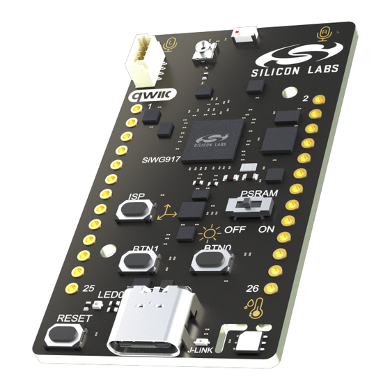
The SiWx917 Wi-Fi 6 and Bluetooth LE Dev Kit is a low-cost,
small form factor development and evaluation platform for the
SiWG917 Wireless System-on-Chip.
The board is a small and cost-effective, feature-rich, prototype and development platform
based on the SiWG917 Wireless System-on-Chip. The SiWx917 Dev Kit is an ideal plat-
form for developing energy-friendly IoT applications.
A built-in SEGGER J-Link debugger ensures easy debugging through the USB Type-C
connector.
silabs.com | Building a more connected world.
Copyright © 2024 by Silicon Laboratories
TARGET DEVICE
• SiWG917 Wireless System-on-Chip
(SiWG917M111MGTBA)
• High-performance 2.4 GHz radio
• 32-bit ARM® Cortex®-M4 with 180 MHz
maximum operating frequency
• 8 MB flash and 320 kB RAM
KIT FEATURES
• 2.4 GHz ceramic chip antenna
• Power control of on-board peripherals for
ultra-low power operation
• Relative humidity and temperature sensor
• Ambient light sensor
• 6-axis inertial sensor
• MEMS stereo microphones
• RGB LED and two push buttons
• 26-pin 2.54 mm breakout pads
• Qwiic® connector
• SEGGER J-Link on-board debugger
• Virtual COM port
• Mini Simplicity connector (not mounted)
for AEM using external Silicon Labs
debugger
• USB powered
SOFTWARE SUPPORT
• Simplicity Studio™
Rev. 1.0
Advertisement
Table of Contents

Related Manuals for Silicon Laboratories SiWx917


Summary of Contents for Silicon Laboratories SiWx917
- Page 1 The board is a small and cost-effective, feature-rich, prototype and development platform • High-performance 2.4 GHz radio based on the SiWG917 Wireless System-on-Chip. The SiWx917 Dev Kit is an ideal plat- • 32-bit ARM® Cortex®-M4 with 180 MHz form for developing energy-friendly IoT applications.
-
Page 2: Table Of Contents
Table of Contents 1. Introduction ....... . 4 1.1 Kit Contents ....... 4 1.2 Getting Started . - Page 3 7.2 Errata ....... . .24 8. Document Revision History ......25 silabs.com | Building a more connected world.
-
Page 4: Introduction
Programming the SiWx917 Dev Kit is easily done using a USB Type-C cable and the on-board J-Link debugger. A USB virtual COM port provides a serial connection to the target application. Included on the board is a 64 Mbit QSPI PSRAM that can be used for running applications. -
Page 5: Kit Hardware Layout
UG581: SiWx917 Wi-Fi 6 and Bluetooth LE Dev Kit User's Guide Introduction 1.4 Kit Hardware Layout SiWx917 Dev Kit layout is shown below. 2.4 GHz Chip Antenna 30.4 mm Right I2S Left I2S Microphone Top View Microphone Bottom View SiWG917... -
Page 6: Specifications
UG581: SiWx917 Wi-Fi 6 and Bluetooth LE Dev Kit User's Guide Specifications 2. Specifications 2.1 Recommended Operating Conditions Parameter Symbol Unit USB Supply Input Voltage — — Supply Input Voltage (VMCU supplied externally) VMCU Operating Temperature — ˚C Note: 1. Brightness of the RGB LED will vary with the supply voltage. Due to manufacturing tolerances, functionality is not guaranteed over the entire working range. -
Page 7: Current Consumption
UG581: SiWx917 Wi-Fi 6 and Bluetooth LE Dev Kit User's Guide Specifications 2.2 Current Consumption The operating current of the board greatly depends on the application. The table below attempts to give some indication of how different features of the board contribute to the overall power consumption. Note that the numbers are taken from the data sheets for the devi- ces. -
Page 8: Hardware
UG581: SiWx917 Wi-Fi 6 and Bluetooth LE Dev Kit User's Guide Hardware 3. Hardware The core of the SiWx917 Dev Kit is the SiWG917 Wireless System-on-Chip. The board also contains several peripherals connected to the SiWG917. Refer to section 1.4 Kit Hardware Layout for placement and layout of the hardware components. -
Page 9: Power Supply
Power can also be applied through the Mini Simplicity connector (or Breakout Pads). There must be no other power sources present on the kit as power is injected directly to the VMCU net. Powering the SiWx917 Dev Kit through the Mini Simplicity connector allows cur- rent measurements using the Advanced Energy Monitoring (AEM) as described in section 4.2 External... -
Page 10: Peripherals
3.4 Peripherals The SiWx917 Dev Kit contains a set of peripherals that can be accessed from the SiWG917. All the peripherals (except QSPI PSRAM) have enable signals which can be used to completely turn off the peripherals that are not in use, or they can be put into a state that draws minuscule amount of power. -
Page 11: Si7021 Relative Humidity And Temperature Sensor
MEMS sensor, signal conditioning, ADC, filters, and different operating modes. The ICS-43434 is a bottom port microphone, and it is placed on the bottom side of SiWx917 Dev Kit with acoustic ventilation holes going through to the top side. These holes let sound waves into the microphone package. -
Page 12: Icm-40627 6-Axis Inertial Sensor
X-, Y-, and Z-axes with integrated 16-bit ADCs and programmable digital filters. On the SiWx917 Dev Kit, the ICM-40627 is connected through a switch. The switch must be enabled by setting UULP_VBAT_GPIO_1 high before it can be used by the application. This enables power to the ICM-40627 and connects the SPI lines used for the sensor to the SiWG917 SPI bus. -
Page 13: Veml6035 Ambient Light Sensor
3.4.5 External Memory The SiWx917 Dev Kit includes a 64 Mbit QSPI PSRAM that is isolated through switch to the SiWG917. The APS6404L-3SQR-ZR de- vice features a high speed, low pin count interface. To keep current consumption down, it is important that the PSRAM is always put in power off mode when not used. -
Page 14: Push Buttons And Rgb Led
UG581: SiWx917 Wi-Fi 6 and Bluetooth LE Dev Kit User's Guide Hardware 3.4.6 Push Buttons and RGB LED The kit has two user push buttons marked BTN0 and BTN1. They are connected directly to the SiWG917 and are debounced by RC filters with a time constant of 1 ms. -
Page 15: On-Board Debugger
3.5 On-board Debugger The SiWx917 Dev Kit contains a microcontroller separate from the SiWG917 Wireless that provides the user with an on-board J-Link debugger through the USB Type-C port. This microcontroller is referred to as the "on-board debugger" and is not programmable by the user. -
Page 16: Connectors
3.6 Connectors The SiWx917 Dev Kit features a Mini Simplicity Connector, a USB Type-C connector, and 26 breakout pads. The connectors are placed on the either side of the board, and their placement and pinout are shown in the figure below. For additional information on the connectors, see the following sub-chapters. -
Page 17: Breakout Pads
The pin-routing on SiWG917 is very flexible, so most peripherals can be routed to any pin. However, pins may be shared between the breakout pads and other functions on the SiWx917 Dev Kit. The table below includes an overview of the EXP header and functionality that is shared with the kit. -
Page 18: Qwiic Connector
The SiWx917 Dev Kit features a Qwiic connector compatible with Qwiic Connect System hardware. The Qwiic connector provides an easy way to expand the functionality of the SiWx917 Dev Kit with sensors, LCDs, and other peripherals over the I C interface. The Qwiic connector is a 4-pin polarized JST connector, which ensures the cable is inserted the right way. -
Page 19: Debugging
4.2 External Debugger. When using an external debugger it is very important to make sure that there is no power source present on the SiWx917 Dev Kit, as the external debugger might source a voltage on the target power domain (VMCU). -
Page 20: External Debugger
Wireless mainboard. It is possible to have the SiWx917 Dev Kit powered by a battery and still use the Mini Simplicity Connector with a Wireless mainboard for debugging and communication. In this case, the power switch on the Wireless mainboard must be set to the "BAT" position and the coin cell battery on the Wireless mainboard must be removed. -
Page 21: Virtual Com Port
UG581: SiWx917 Wi-Fi 6 and Bluetooth LE Dev Kit User's Guide Debugging 4.3 Virtual COM Port The virtual COM port (VCOM) is a connection to a UART on the SiWG917 and allows serial data to be sent and received from the device. -
Page 22: Schematics, Assembly Drawings, And Bom
UG581: SiWx917 Wi-Fi 6 and Bluetooth LE Dev Kit User's Guide Schematics, Assembly Drawings, and BOM 5. Schematics, Assembly Drawings, and BOM Schematics, assembly drawings, and Bill of Materials (BOM) are available through Simplicity Studio when the kit documentation pack- age has been installed. -
Page 23: Kit Revision History And Errata
UG581: SiWx917 Wi-Fi 6 and Bluetooth LE Dev Kit User's Guide Kit Revision History and Errata 6. Kit Revision History and Errata 6.1 Revision History The kit revision can be found printed on the box label of the kit, as outlined in the figure below. The kit revision history is summarized in Table 6.1 Kit Revision History on page... -
Page 24: Board Revision History And Errata
UG581: SiWx917 Wi-Fi 6 and Bluetooth LE Dev Kit User's Guide Board Revision History and Errata 7. Board Revision History and Errata 7.1 Revision History The board revision can be found laser printed on the board, and the board revision history is summarized in Table 7.1 Board Revision... -
Page 25: Document Revision History
UG581: SiWx917 Wi-Fi 6 and Bluetooth LE Dev Kit User's Guide Document Revision History 8. Document Revision History Revision 1.0 September, 2024 • Initial document release. silabs.com | Building a more connected world. Rev. 1.0 | 25... - Page 26 Silicon Labs product in such unauthorized applications. Trademark Information Silicon Laboratories Inc. , Silicon Laboratories , Silicon Labs...
Need help?
Do you have a question about the SiWx917 and is the answer not in the manual?
Questions and answers