Table of Contents
Advertisement
Quick Links
Advertisement
Table of Contents

Related Manuals for Exmark QUEST 406


Summary of Contents for Exmark QUEST 406
- Page 1 QUEST ® For Serial Nos. 406,294,345 & Higher Part No. 4504-741 Rev. C...
- Page 2 To acquire a spark arrester for your unit, see your Engine Service Dealer. For all models that do not have Exmark engines, please refer to the engine manufacturer's information included with the machine. For models with Exmark engines, refer to this manual for information.
-
Page 3: Introduction
All Exmark parts are thoroughly tested and inspected before leaving the factory, however, attention is required on your part if you are to obtain the fullest measure of satisfaction and performance. -
Page 4: Table Of Contents
Operating Tips ..........33 Maintenance ............35 Maintenance Safety..........35 Recommended Maintenance Schedule(s) ....36 Periodic Maintenance ........37 Lubrication.............37 Engine Maintenance........37 Servicing an Exmark Engine......38 Servicing a Kawasaki ® Engine ......44 Cleaning the Blower Housing......48 Fuel System Maintenance .......49 Servicing the Emissions Filter ......49 Electrical System Maintenance......49... -
Page 5: Safety
General Safety This machine is capable of amputating hands and feet This lawn mower has been designed in conformance and of throwing objects. Exmark designed and tested with the American National Standards Institute–B71.1 this lawn mower to offer reasonably safe service;... -
Page 6: Safety And Instructional Decals
Safety Safety and Instructional Decals Safety decals and instructions are easily visible to the operator and are located near any area of potential danger. Replace any decal that is damaged or lost. decal93-7009 93-7009 1. Warning—don't operate the mower with the deflector up or removed;... - Page 7 Safety decal115-9625 115-9625 1. Parking 2. Parking brake—engaged brake—disengaged decal119-8871-1 119-8871 For Models with 34 Inch or 42 Inch Models 1. Height-of-cut decal119-8870 119-8870 For Models with 50 Inch or 60 Inch Mower Decks 1. Height of cut decal121-2989 121-2989 1.
- Page 8 2. Height-of-cut selection decal133-8062 133-8062 decal131-1097 131-1097 Exmark 708cc Engine Only 1. Oil drain decal135-2310 135-2310 1. Machine speed 4. Neutral 2. Fast 5. Reverse 3. Slow...
- Page 9 5. Read the Operator's Manual before performing maintenance. 3. Check the tire pressure every 25 operating hours. decal135-2469 135-2469 34 or 42 Inch Models with Exmark Engine 1. Fast 4. Choke–Off 2. Slow 5. Optional hour meter decalptosymbols accessory PTO Switch Symbols 3.
- Page 10 Safety decal135-2470 135-2470 50 or 60 Inch Models 1. Fast 3. Choke–On 2. Slow 4. Choke–Off decal135-3295 135-3295 This machine complies with the industry standard stability test in the static lateral and longitudinal tests with the maximum recommended slope indicated on the decal. It is important that each operator review the slope operation instructions in the operator’s manual and review the conditions in which the machine is being operated to determine if the machine may be operated in the conditions that day and on that site.
- Page 11 Safety decalbatterysymbols Battery Symbols Some or all of these symbols are on your battery. 1. Explosion hazard 5. Read the Operator's Manual. 9. Flush eyes immediately with water and get medical help fast. 2. No fire, open flames, or smoking 6.
-
Page 12: Specifications
• Engine will stop if either the left, the right, or • Engine Specifications: See your Engine Owner’s both levers are moved from neutral lock position Manual while brake is engaged. • Engine Oil Type: Exmark 4-Cycle Premium Operator Controls Engine Oil • Steering and Motion Control: • RPM: Full Speed: 3300 ±100 (max) RPM (No Load) - Page 13 – 50 and 60 inch S-Series model: Two Hydro Ply Rating Gear ZT2800 Integrated drive systems. Pressure 13 psi 13 psi • Hydraulic Oil Type: Exmark Premium Hydro Oil. (90 kPa) (90 kPa) • Hydraulic Filter—50 and 60 inch S-Series: P/N 109-3321 Cutting Deck •...
-
Page 14: Dimensions
Specifications Dimensions 50 inch Deck 60 inch Deck Drive Wheels 39.1 inches 39.1 inches Overall Width: (99 cm) (99 cm) Caster Wheels 36.9 inches 32.9 inches E-Series (94 cm) (84 cm) 34 inch Deck 42 inch Deck Wheel Base: (Center of Caster Tire to Without Deck 35.6 inches 39.0 inches... -
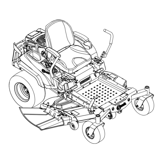
Page 15: Product Overview
Operation Product Overview Operation Note: Determine the left and right sides of the machine from the normal operating position. Controls Become familiar with all the controls before starting the engine and operating the machine. Ignition Switch Located on control panel. The ignition switch is used to start and stop the engine. - Page 16 Operation Note: Brake must be engaged and PTO switch levers outward from the center position into the “OFF” to start engine. (It is not necessary for the T-slot locks them in the neutral position. operator to be in the seat to start the engine.) Turning the key to the “OFF”...
-
Page 17: Before Operation
Do Not overfill fuel tank. Fill the fuel tank to the safely perform the job. Only use accessories and bottom of the filler neck. The empty space in the attachments approved by Exmark. tank allows gasoline to expand. Overfilling may result... - Page 18 Operation in fuel leakage or damage to the engine or emission DANGER system. In certain conditions during fueling, static Make sure you understand the controls, their electricity can be released causing a spark which locations, their functions, and their safety can ignite gasoline vapors.
-
Page 19: Operating Instructions
Operation flame or any enclosed area where open pilot lights or heat appliances are present. Filling the Fuel Tank Use a fuel stabilizer/conditioner in the machine to provide the following benefits: • Keeps gasoline fresh during storage of 30 days or less. - Page 20 Operation guards, switches and other devices in place and in WARNING proper working condition. Operating engine parts, especially the muffler, • Keep clear of the discharge opening at all become extremely hot. Severe burns can occur times. Never mow with the discharge door on contact and debris, such as leaves, grass, raised, removed or altered unless there is a grass brush, etc.
- Page 21 Operation – Whenever you leave the mower. Do Not leave quickly affect the operation of the machine a running machine unattended. on a slope. • Identify hazards at the base of the slope. Do • Stop engine, wait for all moving parts to stop: Not operate the machine near drop offs, ditches, –...
-
Page 22: Checking The Engine Oil Level
Operation grass can hide obstacles. Uneven terrain could Pull up and back on the parking brake lever to overturn the machine. engage the parking brake. • Use extra care while operating with accessories Disengage the blades by pushing down the blade or attachments, such as grass collection systems. -
Page 23: Operating The Blades
“SLOW” and engine, including the mower deck and cutting blades. “FAST” positions. • For Exmark Engines: Place the throttle in the Engaging the Blades “FAST” position. Disengage the parking brake. -
Page 24: The Safety Interlock System
Operation The Safety Interlock System Understanding the Safety Interlock System CAUTION The safety interlock system is designed to prevent the If the safety interlock switches are disconnected engine from starting unless: or damaged the machine could operate • The blades are disengaged. unexpectedly causing personal injury. - Page 25 Operation Check Engine Starting Circuit Chart Note: In the Check Engine Starting Circuit Chart, the state of system item that is bold is being checked in each scenario. System Parking Brake Motion Control Levers Operator Outcome (Blades) Engaged Disengaged Both levers moved in, or either Operator Starter must in seat...
- Page 26 Operation Check Shutdown Circuit Chart Note: The state of system item(s) that is bold is being checked in each scenario. System Engine Parking Motion Control Operator Outcome Brake (Blades) Levers Running idle Disengaged Disengaged Both levers moved Raise off Engine must (1/3 throttle) out (neutral lock), of seat (but...
-
Page 27: Driving Forward Or Backward
Operation Driving Forward or Backward The throttle control regulates the engine speed as measured in rpm (revolutions per minute). Place the throttle control in the Fast position for best performance. Always operate in the Fast (full throttle) position. CAUTION Machine can spin very rapidly by positioning one lever too much ahead of the other. -
Page 28: Stopping The Machine
• For All Engines except Exmark: Place the deck. throttle midway between the “SLOW” and “FAST” positions. • For Exmark Engines: Place the throttle in the “FAST” position. Allow the engine to run for a minimum of 15 seconds, then turn the ignition switch to the “OFF”... -
Page 29: Positioning The Seat
Operation Move the seat to the desired position and tighten bolts. Tip the seat back to the closed position. • S-Series Units: Push the adjustment lever towards the center of the machine to release the seat adjuster track (Figure 17). g015168 Figure 15 For cutting heights above 3 1/2 inches (90 mm) use the... -
Page 30: Adjusting The Motion Control Levers
Operation Move the control lever to the next set of holes. Secure the lever with the hardware. Repeat the adjustment for the opposite control lever. Adjusting the Tilt The motion control levers can be tilted fore or aft for maximum operator comfort. Loosen the upper bolt holding the control lever to the control arm shaft. -
Page 31: Side Discharge
Operation DANGER Without the discharge deflector, mulch kit, or entire grass collection system mounted in place, you and others are exposed to blade contact and thrown debris. Contact with rotating mower blade(s) and thrown debris will cause injury or death. •... - Page 32 Operation To transport the machine: • Lock the brake and block the wheels. • Be sure the fuel shut-off valve is closed. • Securely fasten the machine to the trailer or truck with straps, chains, cable, or ropes. Only use the g027995 designated tie-down locations on the mower as Figure 22...
-
Page 33: Operating Tips
Operation • Never allow children or others in or on towed equipment. • On slopes, the weight of the towed equipment may cause loss of traction, increased risk of rollover, and loss of control. Reduce the towed weight and slow down. •... - Page 34 File down any nicks and sharpen the blades as necessary. If a blade is damaged or worn, replace it immediately with a genuine Exmark replacement blade. Only Exmark blades are to be used with this unit. No other blades are approved.
-
Page 35: Maintenance
While maintenance or adjustments are being to the original equipment or failure to use made, someone could start the engine. original Exmark parts could lead to serious Accidental starting of the engine could seriously injury or death. Unauthorized changes to the injure you or other bystanders. -
Page 36: Recommended Maintenance Schedule(S)
• Clean the grass and debris build-up from the machine and cutting deck. • Clean the engine and exhaust system area. • Grease all lubrication points. • Clean the air cleaner foam element (more often in dusty, dirty conditions)(Exmark engine). Every 25 hours • Check the tire pressure. -
Page 37: Periodic Maintenance
Grease the front caster wheels (Figure 24). Important: If you are using a machine with an Exmark engine above 5,000 ft (1500 m) for a continuous period, ensure that the High Altitude Kit has been installed so that the engine meets... -
Page 38: Servicing An Exmark Engine
To locate a first)—Clean the air dealer convenient to you, access our web site at cleaner foam element http://www.Exmark.com or contact our Exmark (more often in dusty, Customer Care Department at the number(s) dirty conditions)(Exmark listed in your Emission Control Warranty engine). - Page 39 Replace the paper element if it is damaged or cannot be cleaned g027800 thoroughly. Figure 26 To learn more about the Exmark twin-cylinder engine go to https://exmark.com/engines or scan the QR code. g028322 Figure 29 702 and 708cc Engine...
- Page 40 If the level is low, wipe off the area around the oil the parking brake is engaged. fill cap, remove cap/dipstick and add oil to the “FULL” mark on the dipstick. Exmark 4-Cycle Stop the engine, remove the key, and wait for all Premium Engine Oil is recommended; refer to...
- Page 41 Maintenance g027799 Figure 32 g029570 Figure 33 Change the engine oil filter. Apply a thin film of clean Exmark 4-Cycle Premium Engine Oil to the rubber gasket on the new filter.
- Page 42 Checking the Engine Oil Level section. years (whichever comes first)—Replace the spark plug (Exmark engine). Ensure that the air gap between the center and side electrodes is correct before installing the spark plug. Use a spark plug wrench for removing and installing the spark plug and a gapping tool or feeler gauge to check and adjust the air gap.
- Page 43 The spark plug is most accessible when the blower Inspect the spark plug housing is removed for cleaning. Note: If you see light brown or gray on the Installing the Spark Plug–Exmark insulator, the engine is operating properly. A black coating on the insulator usually means the Engine air cleaner is dirty.
-
Page 44: Servicing A Kawasaki Engine
Maintenance Servicing a Kawasaki ® Engine Servicing the Air Cleaner Service Interval: Every 250 hours—Replace the primary air filter (more often under extremely dusty, dirty conditions)(Kawasaki engine). g032301 Every 250 hours—Check Figure 39 the safety air filter 1. Air cleaner body 4. - Page 45 If the level is low, wipe off the area around the oil fill cap, remove cap/dipstick and add oil to the “FULL” mark on the dipstick. Exmark 4-Cycle Premium Engine Oil is recommended; refer to the following information for an appropriate API...
- Page 46 Service Interval: After the first 5 hours Change the engine oil filter. Apply a thin film of Every 100 hours (change clean Exmark 4-Cycle Premium Engine Oil to the it more often under a rubber gasket on the new filter.
- Page 47 Maintenance g027660 Figure 44 g027477 Figure 43 Check the oil level; refer to Checking the Engine Oil–Kawasaki Engine section. Start the engine and check for leaks. Note: Ensure the oil filter gasket touches the engine, then an extra 3/4 turn is completed. Servicing the Spark Plug Note: Dispose of the used oil at a recycling center.
-
Page 48: Cleaning The Blower Housing
Maintenance Checking the Spark Plug Air Gap: 0.030 inch (.76 mm) Disengage the PTO and ensure the parking brake Inspect the spark plug is engaged. Note: If you see light brown or gray on the Stop the engine, remove the key, and wait for all insulator, the engine is operating properly. -
Page 49: Fuel System Maintenance
Maintenance Fuel System Maintenance Remove the filter from the fuel lines. Install a new filter with the flow direction arrow coming from the fuel tank and pointing to the Replacing the Fuel Filter engine. Move the hose clamps close to the filter Service Interval: Every 100 hours/Yearly to secure it in place. - Page 50 Maintenance DANGER Battery electrolyte contains sulfuric acid, which is poisonous and can cause severe burns. Swallowing electrolyte can be fatal or if it touches skin can cause severe burns. • Wear safety glasses to shield eyes, and rubber gloves to protect skin and clothing when handling electrolyte.
- Page 51 Maintenance Note: To prevent damage due to freezing, DANGER battery should be fully charged before putting Jump starting a weak battery that is cracked, away for winter storage. frozen, has low electrolyte level, or an Check the voltage of the battery with a digital open/shorted battery cell, can cause an voltmeter.
-
Page 52: Drive System Maintenance
Maintenance Servicing the Fuses Service Interval: As required The electrical system is protected by fuses. It requires no maintenance; however, if a fuse blows, check the component/circuit for a malfunction or short. Fuse: • Main F1-30 amp, blade-type • Charge Circuit F2-25 amp, blade-type g012785 Figure 50 Remove and retain the screw securing the control... -
Page 53: Changing The Hydraulic System Filter And Oil--50 And 60 Inch S-Series Only
Maintenance Remove the mounting hardware holding the transaxle support in place (Figure 54). g007275 Figure 52 1. Valve stem Changing the Hydraulic g272058 System Filter and Oil––50 Figure 54 and 60 Inch S-Series Only 1. Transaxle support 3. Filter and guards 2. -
Page 54: Mower Maintenance
Maintenance Installing the Hydraulic System Install the transaxle guard. Refer to for the correct Filters torque values for the nuts and bolts. Proceed to the Bleeding the Hydraulic System section. Important: Failure to perform the Bleeding the Hydraulic System procedure after changing hydraulic filters and oil can result in irreparable damage to the transaxle drive system. - Page 55 Note: The machine must be on a level surface for the blades as necessary. If a blade is damaged or the following procedure. worn, replace it immediately with a genuine Exmark replacement blade. For convenient sharpening and Raise the mower deck to the highest height-of-cut replacement, you may want to keep extra blades on position;...
- Page 56 The blades must be replaced if a solid object is hit, if the blade is out of balance, or the blade is bent. To ensure optimum performance and continued safety conformance of the machine, use genuine Exmark replacement blades. Replacement blades made by other manufacturers may result in an unsafe machine.
-
Page 57: Leveling The Mower Deck
Always install the original Exmark blades, washers and blade bolts as shown. g007276 Figure 62 Leveling the Mower Deck 1. - Page 58 Maintenance Loosen the side-locking nut. Raise or lower the left side of the mower deck by rotating the rear nut. (Figure 66). Note: Rotate the rear nut clockwise to raise the mower deck; rotate the rear nut counter-clockwise to lower the mower deck. g009682 Figure 64 Mower Deck with 2 Blades...
- Page 59 Maintenance Carefully rotate the blades so they are facing front to rear (Figure 67 and Figure 68). g272080 Figure 69 1. Adjusting rod 3. Lock nut g009658 2. Adjusting block Figure 67 Mower Deck with 2 Blades To raise the front of the mower, tighten the 1.
-
Page 60: Mower Belt Maintenance
Maintenance g005077 Figure 72 1. Mower deck 3. Rear lift rod 2. Hanger bracket Slide the mower deck rearward to remove the mower belt from the engine pulley. g014635 Figure 70 Slide the mower deck out from underneath the 1. Front support rod 3. -
Page 61: Replacing The Discharge Deflector
Maintenance Using a spring removal tool, (P/N 92-5771), Install the mower belt onto the engine pulley; remove the idler spring from the deck hook to refer to Replacing the Mower Belt. remove tension on the idler pulley and roll the Level the deck;... - Page 62 Maintenance g017618 Figure 75 1. Rod and spring 3. Rod, short end, moved assembly installed behind mower bracket 2. Loop end of the spring 4. Short end, retained by installed into the notch in mower bracket. the deflector bracket Secure the rod and spring assembly by twisting it so the short end of the rod can be placed behind the front bracket welded to the deck (Figure 75).
-
Page 63: Cleaning
Maintenance Cleaning Stop engine, wait for all moving parts to stop, and remove key. Engage parking brake. Clean all debris from rotating engine air intake Clean Grass Build-Up Under screen, around engine shrouding, and exhaust Deck system area. Wipe up any excessive grease or oil around the Service Interval: Before each use or daily engine and exhaust system area. -
Page 64: Troubleshooting
Troubleshooting Troubleshooting Important: It is essential that all operator safety mechanisms be connected and in proper operating condition prior to mower use. When a problem occurs, Do Not overlook the simple causes. For example: starting problems could be caused by an empty fuel tank. The following table lists some of the common causes of trouble. - Page 65 Troubleshooting Problem Possible Cause Corrective Action Engine loses power 1. Engine load is excessive. 1. Reduce the ground speed. 2. Air cleaner is dirty. 2. Clean or replace the air cleaner element. 3. Oil level in the crankcase is low. 3.
-
Page 66: Schematics
Schematics Schematics Electrical Logic Schematic g201257... -
Page 67: Information
While the exposure from Exmark products may be negligible or well within the “no significant risk” range, out of an abundance of caution, Exmark has elected to provide the Prop 65 warnings. Moreover, if Exmark does not provide these warnings, it could be sued by the State of California or by... - Page 68 Notes:...
- Page 69 Service Record Date: Description of Work Done: Service Done By:...
- Page 71 g011841 Figure 76 This page may be copied for personal use. 1. The maximum slope you can operate the machine on is 15 degrees. Use the slope indicator to determine the degree of slope of hills before operating. Do Not operate this machine on a slope greater than 15 degrees. Fold along the appropriate line to match the recommended slope.
- Page 72 Pack) or Fill in Below Engine Model No. and Spec. No. Model No. Engine Serial No. (E/No) Serial No. ©2020 Exmark Mfg. Co., Inc. Part No. 4504-741 Rev. C 2101 Ashland Ave (402) 223-6375 Beatrice, NE 68310 Fax (402) 223-5489...
Need help?
Do you have a question about the QUEST 406 and is the answer not in the manual?
Questions and answers