Exmark QUEST Operator's Manual
Hide thumbs
Also See for QUEST:
- Operator's manual (64 pages) ,
- Setup instructions (3 pages) ,
- Parts manual (24 pages)
Table of Contents
Advertisement
Advertisement
Table of Contents

Related Manuals for Exmark QUEST


Summary of Contents for Exmark QUEST
- Page 1 QUEST ® For Serial Nos. 850,000 & Higher Part No. 4500-523 Rev. B...
- Page 2 As configured to meet safety, emission, and operating requirements, the actual engine horsepower on this class of lawn mower will be significantly lower. ©2010 Exmark Mfg. Co., Inc. Contact us at www.Exmark.com. Industrial Park Box 808 Printed in the USA...
-
Page 3: Introduction
Whenever you need service, genuine Exmark parts, or additional information, contact an Authorized Service Dealer or Exmark Customer Service and have the model and serial numbers of your product ready. Figure 1 identifies the location of the model and serial numbers on the product. -
Page 4: Table Of Contents
Contents Checking the Tire Pressure ......39 Mower Maintenance ........40 Servicing the Cutting Blades ......40 Introduction ............3 Mower Belt Maintenance ....... 42 Safety ..............5 Leveling the Mower Deck ......43 Safety Alert Symbol ......... 5 Adjusting the Blade Slope ......44 Safe Operating Practices ........ -
Page 5: Safety
Safety Safety • Allow only responsible adults who are familiar with the instructions to operate the machine. • Clear the area of objects such as rocks, toys, wire, Safety Alert Symbol etc., which could be picked up and thrown by the blade. -
Page 6: Slope Operation
• Avoid sudden starts when mowing uphill because Towing the mower may tip backwards. • Use for towing only if equipped with an Exmark • Be aware that operating on wet grass, across steep hitch kit. Do Not attach towed equipment except slopes or downhill may cause the mower to lose at the hitch point. - Page 7 • Use only genuine Exmark replacement parts to ensure that original standards are maintained. • Never fill containers inside a vehicle or on a truck or trailer with a plastic liner.
- Page 8 Safety • Use only Exmark approved attachments. Warranty may be voided if used with unapproved attachments. • If loading the machine onto a trailer or truck, use a single, full-width ramp only. The ramp angle should not exceed 15 degrees.
-
Page 9: Safety And Instructional Decals
Safety Safety and Instructional Decals Safety decals and instructions are easily visible to the operator and are located near any area of potential danger. Replace any decal that is damaged or lost. 93-7009 1. Warning–Do Not operate 2. Cutting/dismemberment the mower with the hazard of hand or foot, discharge deflector up mower blade–stay away... - Page 10 Safety 109-9120 1. Fuse 2. Diode 109-6035 Deck Drive Belt Routing 109-6036 1. Read the Operator’s Manual. 109-9173 2. Remove the ignition key and read the instructions before servicing or performing maintenance. 1. Parking brake 4. Neutral 3. Height of cut. 2.
- Page 11 Safety 110-6691 1. Thrown objects 3. Cutting/dismemberment hazard–keep bystanders of hand or foot–stay a safe distance from the away from moving parts. machine. 2. Thrown objects hazard, mower–keep the discharge deflector or collection system in place. 116-0532 QST20BE422 Unit 1. Choke–on 2.
- Page 12 Safety 117–2718 PTO Symbols 1. PTO—Off 2. PTO—On 109-8965 1. Warning–read the Operator’s Manual. 5. Tipping hazard–avoid sudden and sharp turns while on slopes, only mow across slopes less than 15 degrees, keep a safe distance from water, and only mow up and down slopes less than 15 degrees.
- Page 13 Safety 116-2321 1. Read the instructions before servicing or performing 4. Check hydraulic oil level and refer to the Operator’s maintenance. Manual for further instructions. 2. Time interval 5. Check tire pressure. 3. Check oil level. 6. Refer to the Operator’s manual for grease instructions. Battery Symbols Some or all of these symbols are on your battery.
-
Page 14: Specifications
Specifications Specifications Model Numbers Serial Nos: 850,000 and Higher QST20BE422; QST22BE482; QST24BE522; QST22BE482C; QST24BE522C Systems engine. (It is not necessary for the operator to be in the seat to start the engine.) Engine • Operator must be in seat when PTO is engaged, •... -
Page 15: Dimensions
Integrated drive systems. engine shaft. Blades are driven by one belt (w/self-tensioning idler) direct from the engine. • Hydraulic Oil Type: Exmark Premium Hydro oil. • Deck: Full floating deck is attached to out-front • Speeds: support frame. Maximum turf protection is –... -
Page 16: Torque Requirements
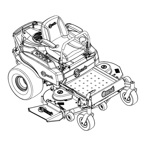
Product Overview Overall Height: Product Overview All Units 41.8 inches (106 cm) Tread Width: (Center to Center of Tires, Widthwise) 42 inch 48 inch 52 inch Deck Deck Deck Drive 36.0 inches 36.0 inches 36.8 inches Wheels (91 cm) (91 cm) (93 cm) Caster 27.9 inches... -
Page 17: Operation
Operation Operation Blade Control Switch (Power Take-Off) Controls Located on the control panel. The blade control switch, represented by a power Note: Become familiar with all of the controls in take-off (PTO) symbol, engages and disengages Figure 3 and Figure 4 before you start the engine and power to the mower blades (see Figure 4). -
Page 18: Operating Instructions
Operation Parking Brake Lever DANGER Located on left side of the console (Figure 3). Mowing on wet grass or steep slopes can cause sliding and loss of control. Wheels dropping The brake lever engages a parking brake on the drive over edges can cause rollovers, which may result wheels. - Page 19 Operation Important: Never use methanol, gasoline DANGER containing methanol, gasohol containing more In certain conditions during fueling, static than 10% ethanol, premium gasoline, or white electricity can be released causing a spark which gas because the fuel system could be damaged. can ignite gasoline vapors.
-
Page 20: Checking The Engine Oil Level
Operation Using Stabilizer/Conditioner Use a fuel stabilizer/conditioner in the machine to provide the following benefits: • Keeps gasoline fresh during storage of 30 days or less. For longer storage it is recommended that the fuel tank be drained. • Cleans the engine while it runs. •... -
Page 21: Operating The Blades
Operation 2. Move the throttle midway to the Fast position. Note: Always engage the blades with the throttle in the midway position. 3. Pull out on the blade control switch, to the On position, to engage the blades (Figure 8). Figure 7 1. -
Page 22: The Safety Interlock System
• The parking brake is disengaged and the operator Note: If machine does not pass any of these tests, gets off machine. Do Not operate. Contact your authorized EXMARK • The PTO is engaged and the operator gets off SERVICE DEALER. -
Page 23: Stopping The Machine
Operation Forward Stopping the Machine 1. Move the levers to the center, unlocked position. To stop the machine, move the motion control 2. To go forward, slowly push the motion control levers to neutral and outward to the neutral position, levers forward (Figure 9). -
Page 24: Adjusting The Anti-Scalp Rollers
Operation Adjusting the Anti-Scalp • 48 and 52 Inch Units: Rollers 1. Push the adjustment lever towards the center of the machine to release the seat adjuster It is recommended to change the anti-scalp roller track (Figure 12). position when the height of cut has changed. 1. -
Page 25: Adjusting The Motion Control Levers
Operation 2. Move the control lever to the next set of holes. Secure the lever with the hardware. 3. Repeat the adjustment for the opposite control lever. Adjusting the Tilt The motion control levers can be tilted fore or aft for maximum operator comfort. -
Page 26: Side Discharge
Operation DANGER Without the discharge deflector, mulch kit, or entire grass collection system mounted in place, you and others are exposed to blade contact and thrown debris. Contact with rotating mower blade(s) and thrown debris will cause injury or death. •... -
Page 27: Operating Tips
Operation Operating Tips WARNING Loading a unit on a trailer or truck increases Fast Throttle Setting the possibility of backward tip-over. Backward tip-over could cause serious injury or death. For best mowing and maximum air circulation, operate the engine at the Fast position. Air is required •... -
Page 28: Blade Maintenance
File down any nicks and sharpen the blades as necessary. If a blade is damaged or worn, replace it immediately with a genuine Exmark replacement blade. Only Exmark blades are to be used with this unit. No other blades are approved. -
Page 29: Maintenance
Failure to use original Exmark parts could cause serious injury or Remove the key from the ignition switch, engage death. parking brake, and pull the wire(s) off the spark plug(s) before you do any maintenance. -
Page 30: Premaintenance Procedures
Maintenance Maintenance Service Maintenance Procedure Interval • Charge the battery and disconnect the battery cables. • Perform all maintenance procedures before storage. Before storage • Paint any chipped surfaces. Monthly • Check the battery charge. Important: Refer to your Engine Operator’s Manual for additional maintenance procedures. Premaintenance Periodic Maintenance Procedures... -
Page 31: Engine Maintenance
Maintenance Engine Maintenance Servicing Paper Element Service Interval: Every 25 hours/Monthly Servicing the Air Cleaner (whichever comes first) (May need more often Service Interval: Every 25 hours/Monthly under extremely dusty or (whichever comes first) dirty conditions.) (May need more often Every 100 hours/Yearly under extremely dusty or (whichever comes... - Page 32 Maintenance 3. Stop the engine, remove the key, and wait for all moving parts to stop before leaving the operating position. 4. Clean the area around the drain plug and on the machine frame. Place a pan underneath machine directly below the drain hole in the frame as shown in Figure 20.
-
Page 33: Checking The Hydraulic Oil Level
14. Slowly add additional oil to bring it to the full Important: Before reinstalling new filters, mark. Do Not overfill. apply a thin coat of Exmark Premium Hydro oil on the surface of the filters rubber seal. 15. Install the oil fill cap/dipstick and push firmly into place. -
Page 34: Servicing The Spark Plug
Maintenance 6 times). Check the oil level, and add oil as required after stopping the engine. C. It may be necessary to repeat steps A and B until all the air is completely purged from the system. When the transaxle operates at normal noise levels and moves smoothly forward and reverse at normal speeds, then the transaxle is considered purged. -
Page 35: Cleaning The Blower Housing
Maintenance Cleaning the Blower Housing Service Interval: Every 100 hours/Yearly (whichever comes first) More often under dirty conditions. To ensure proper cooling, make sure the grass screen, cooling fins, and other external surfaces of the engine are kept clean at all times. 1. -
Page 36: Electrical System Maintenance
Maintenance Charging the Battery Removing the Battery WARNING Battery terminals or metal tools could short against metal machine components causing sparks. Sparks can cause the battery gasses to explode, resulting in personal injury. • When removing or installing the battery, Do Not allow the battery terminals to touch any metal parts of the machine. - Page 37 Maintenance CAUTION WARNING If the ignition is in the “ON” position there Incorrect battery cable routing could damage is potential for sparks and engagement of the machine and cables causing sparks. components. Sparks could cause an explosion or Sparks can cause the battery gasses to moving parts could accidentally engage causing explode, resulting in personal injury.
-
Page 38: Recommended Jump Starting Procedure
Maintenance Voltage Percent Maximum Charging CAUTION Reading Charge Charger Interval Connecting the jumper cables incorrectly Settings (wrong polarity) can immediately damage the 12.4 – 12.6 75–100% 30 Minutes 16 volts/7 electrical system. amps Be certain of battery terminal polarity and 12.2 –... -
Page 39: Servicing The Fuses And Relay
Maintenance 4. Connect the other end of the positive cable to the positive terminal of the booster battery. 5. Connect the black negative (–) cable to the other terminal (negative) of the booster battery. 6. MAKE THE FINAL CONNECTION ON THE ENGINE BLOCK OF THE STALLED VEHICLE (NOT TO THE NEGATIVE POST) AWAY FROM THE BATTERY. -
Page 40: Mower Maintenance
(Figure 32 and Figure 33). Measure the blades as necessary. If a blade is damaged or from a level surface to the cutting edge, of the worn, replace it immediately with a genuine Exmark blades. Note this dimension. replacement blade. For convenient sharpening and replacement, you may want to keep extra blades on hand. -
Page 41: Removing The Blades
To ensure optimum performance and continued safety Figure 33 conformance of the machine, use genuine Exmark 42 Inch Deck replacement blades. Replacement blades made by 1. Blades front to rear 2. -
Page 42: Mower Belt Maintenance
WARNING Incorrect installation of the blade or components used to retain the blade cause the blade to come loose and could seriously injure or kill you or bystanders. Always install the original Exmark blades, washers and blade bolts as shown. -
Page 43: Leveling The Mower Deck
Maintenance 1. Park the machine on a level surface and disengage the blade control switch. 2. Move the motion control levers outward to the neutral position, engage parking brake, stop the engine, remove the key, and wait for all moving parts to stop before leaving the operating position. -
Page 44: Adjusting The Blade Slope
Maintenance 6. Set anti-scalp rollers to top holes or remove 4. Check the air pressure of all four tires. If needed, completely for this adjustment. adjust to the recommended inflation; refer to Checking the Tire Pressure in Drive System 7. Set the height-of-cut lever to the 3 inch (76 mm) Maintenance section. -
Page 45: Replacing The Discharge Deflector
Maintenance Replacing the Discharge 9. Measure from the tip of the front blade to the flat surface and the tip of the rear blade to the Deflector flat surface (Figure 42 and Figure 43). If the front blade tip is not “R” (see Block Height and Rake DANGER Table in Leveling the Mower Deck) lower than the rear blade tip, adjust the front deck hanger. -
Page 46: Adjustments
Maintenance Adjustments through the front discharge deflector bracket, discharge deflector, and rear deflector bracket. 5. Make sure that the spring and rod are installed Tracking Adjustment so that the rod is retained from sliding out by the front bracket and the spring holds the If the machine turns right or left when handles are discharge deflector in the down position. -
Page 47: Cleaning
Maintenance Cleaning 6. If adjustment is necessary, loosen the jam nut from the yoke on the side that needs adjustment. Remove the hairpin and clevis pin (see Figure 46). Washing the Underside of the Mower Service Interval: Before each use or daily After each use, wash the underside of the mower to prevent grass buildup for improved mulch action and clipping dispersal. - Page 48 Maintenance Note: If the mower is not clean after one washing, soak it and let it stand for 30 minutes. Then repeat the process. 8. Run the mower again for one to three minutes to remove excess water. WARNING A broken or missing washout fitting could expose you and others to thrown objects or blade contact.
-
Page 49: Storage
Storage Storage D. Restart the engine and run it until it stops. E. Choke the engine. Start and run the engine Cleaning and Storage until it will not start. 10. Remove the spark plug(s) and check its condition; 1. Disengage the blade control switch, move the refer to Servicing the Spark Plug in Engine motion controls outward to the neutral position, Maintenance section. -
Page 50: Troubleshooting
Troubleshooting Troubleshooting Important: It is essential that all operator safety mechanisms be connected and in proper operating condition prior to mower use. When a problem occurs, Do Not overlook the simple causes. For example: starting problems could be caused by an empty fuel tank. The following table lists some of the common causes of trouble. - Page 51 Troubleshooting Problem Possible Cause Corrective Action Engine loses power 1. Engine load is excessive. 1. Reduce the ground speed. 2. Air cleaner is dirty. 2. Clean or replace the air cleaner element. 3. Oil level in the crankcase is low. 3.
-
Page 52: Schematics
Schematics Schematics Electrical Diagram ENGINE BLUE BROWN GREEN ORANGE PINK PINK BLUE VIOLET GREEN PINK BLACK BROWN BLACK BROWN GREEN G009785... - Page 53 Schematics Electrical Logic Schematic GREEN GREEN BROWN BROWN VIOLET ORANGE ORANGE VIOLET BROWN GREEN ORANGE ORANGE PINK PINK VIOLET BLUE BLUE ORANGE VIOLET GREEN GREEN GREEN BLACK PINK PINK PINK BLACK BROWN BLACK BROWN WHITE BROWN YELLOW YELLOW GRAY G009777...
- Page 54 To locate a dealer convenient to you, access our website at discretion) to be defective in factory materials or workmanship for a www.exmark.com. U.S. or Canada customers may also call period of three years for residential usage of Exmark Quest turf 402-223-6375. equipment.
- Page 55 Notes:...
- Page 56 Notes:...
-
Page 57: Service Record
Service Record Date: Description of Work Done: Service Done By:... - Page 60 SEE EXMARK’S COMPLETE LINE OF ACCESSORIES AND OPTIONS MID-MOUNT RIDING ACCESSORIES AND OPTIONS CUSTOM RIDE SEAT SUSPENSION SYSTEM OPERATOR CONTROLLED DISCHARGE FULL SUSPENSION SEAT ROLL OVER PROTECTION SYSTEM (ROPS) DECK LIFT ASSIST KIT SUN SHADE HITCH KIT TRASH CONTAINER LIGHT KIT...
Need help?
Do you have a question about the QUEST and is the answer not in the manual?
Questions and answers
What are the lenghts of the belts on this mower
WHAT WEIGHT OIL DO I USE IN MOWER?
The Exmark QUEST mower should use 10W30 synthetic blend oil.
This answer is automatically generated