Advertisement

QUEST
®
For Serial Nos.
413,950,474 & Higher
Part No. 4506-583 Rev. A

Advertisement

Table of Contents
loading
Need help?

Need help?

Do you have a question about the QUEST S Series and is the answer not in the manual?

Questions and answers

David
January 19, 2025

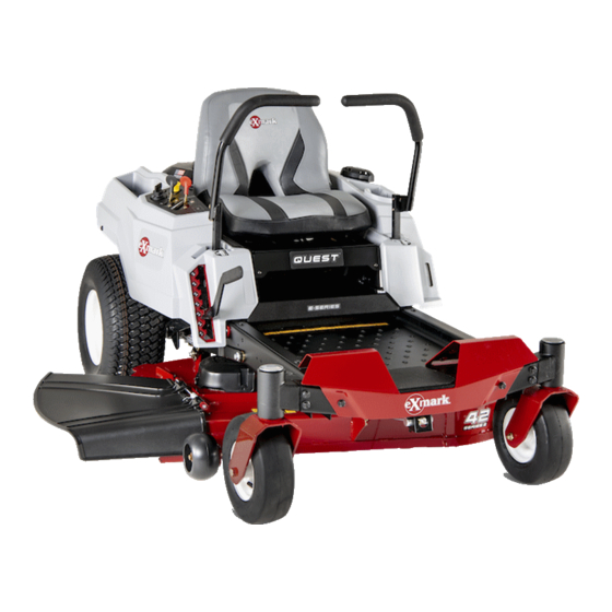
what's the size of the rear tires on a 2018 Exmark Quest S Series 50 " cut

1 comments:
Mr. Anderson
February 4, 2025

The rear tires on a 2018 Exmark Quest S Series 50" cut have a pressure specification of 13 psi (90 kPa). However, the exact size of the rear tires is not specified in the provided context.

This answer is automatically generated

Thomas Davis
March 10, 2025

how much oil goes in the hydro trans exmart quest

Subscribe to Our Youtube Channel

Summary of Contents for Exmark QUEST S Series

  • Page 1 QUEST ® For Serial Nos. 413,950,474 & Higher Part No. 4506-583 Rev. A...
  • Page 2 To acquire a spark arrester for your unit, see your Engine Service Dealer. For all models that do not have Exmark engines, please refer to the engine manufacturer's information included with the machine. For models with Exmark engines, refer to this manual for information.
  • Page 3: Introduction

    Introduction Whenever you need service, genuine Exmark parts, or additional information, contact an Authorized Service Dealer or Exmark Customer Service and have CONGRATULATIONS on the purchase of your the model and serial numbers of your product ready. Exmark Mower. This product has been carefully...
  • Page 4: Table Of Contents

    Maintenance Safety..........40 Recommended Maintenance Schedule(s) ....41 Periodic Maintenance ........41 Lubrication.............42 Engine Safety ..........42 Engine Maintenance........42 Servicing an Exmark Engine......42 Servicing a Kohler Engine ......48 Cleaning the Blower Housing......52 Fuel System Maintenance .......53 Electrical System Maintenance......53 Charging the Battery........53 Drive System Maintenance ......56...
  • Page 5: Safety

    Safety Safety General Safety This machine is capable of amputating hands and This machine has been designed in conformance feet and of throwing objects. Always follow all safety with the American National Standards Institute instructions to avoid serious personal injury or death. B71.1 for Consumer Turf Care Equipment–Safety •...
  • Page 6: Safety And Instructional Decals

    Safety Safety and Instructional Decals Safety decals and instructions are easily visible to the operator and are located near any area of potential danger. Replace any decal that is damaged or lost. decal93-7009 93-7009 1. Warning—don't operate the mower with the deflector up or removed;...
  • Page 7 2. Height of cut collection system in place. decal131-1097 131-1097 Exmark 708cc Engine Only 1. Oil drain decal139-2392 139-2392 For E-Series Models...
  • Page 8 Safety decal139-2394 139-2394 E- and S-Series Models 1. Traction controls 4. Neutral 2. Fast 5. Reverse 3. Slow 6. Parking brake decal139-5892 139-5892 decal139-2395 139-2395 For All Models Except E-Series E- and S-Series Models 1. Height of cut 1. Parking brake 4.
  • Page 9 Safety decal142-5861 decal142-5862 142-5861 142-5862 Models without Hour Meter Models with Hour Meter 1. Fast 4. Choke–Off 1. Fast 3. Choke–On 2. Slow 5. Optional hour meter 2. Slow 4. Choke–Off accessory 3. Choke–On decal142-5864 142-5864 decal142-9946 142-9946 X-Series Models...
  • Page 10 Safety decalptosymbols PTO Switch Symbols decal146-0889 1. PTO–disengage 2. PTO–engage 146-0889 X-Series Models 1. Traction controls 4. Neutral 2. Fast 5. Reverse 3. Slow decal146-0890 146-0890 X-Series Models 1. Traction controls 4. Neutral 2. Fast 5. Reverse 3. Slow decal146-0900 146-0900 X-Series Models 1.
  • Page 11 Safety decal144-5288 144-5288 This machine complies with the industry standard stability test in the static lateral and longitudinal tests with the maximum recommended slope indicated on the decal. It is important that each operator review the slope operation instructions in the operator’s manual and review the conditions in which the machine is being operated to determine if the machine may be operated in the conditions that day and on that site.
  • Page 12 Safety decalbatterysymbols Battery Symbols Some or all of these symbols are on your battery. 1. Explosion hazard 5. Read the Operator's Manual. 9. Flush eyes immediately with water and get medical help fast. 2. No fire, open flames, or smoking 6.
  • Page 13: Specifications

    Engine or engine will stop. • Engine Specifications: See your Engine Owner’s Manual Operator Controls • Engine Oil Type: Exmark 4-Cycle Premium • Steering and Motion Control: Engine Oil Note: Motion control levers are adjustable to • RPM: two heights.
  • Page 14 Ply Rating ZT2800 Integrated drive systems. Pressure 13 psi 13 psi (90 kPa) (90 kPa) • Hydraulic Oil Type: Exmark Premium Hydro Oil. • Speeds: Front Caster – E- and S-Series Models: Pneumatic (Air-Filled) 0-7.0 mph (11.3 km/hr) forward. Deck Size...
  • Page 15: Dimensions

    Specifications Dimensions Deck design allows for bagging, mulching or side discharge. Overall Width: • Deck Depth: – 42 inch Deck: 4.0 inches (10.2 cm) E-Series – 48 inch Deck: 5.0 inches (12.7 cm) 42 inch Deck 50 inch Deck – 50 inch Deck: 4.0 inches (10.2 cm) Without Deck 40.4 inches 43.1 inches...
  • Page 16: Torque Requirements

    Specifications Tread Width: (Center to Center of Bolt Location Torque Tires, Widthwise) Blade Mounting Bolt 60-80 ft-lb (81-108 N-m) E- and S-Series 42 inch Deck 48 inch Deck Blade Mounting Bolt 50-60 ft-lb (68-81 N-m) Drive Wheels 33.0 inches 37.3 inches X-Series (84 cm) (95 cm)
  • Page 17: Product Overview

    Operation Product Overview Operation Note: Determine the left and right sides of the machine from the normal operating position. Controls Become familiar with all the controls before starting the engine and operating the machine. Ignition Switch Located on control panel. The ignition switch is used to start and stop the engine.
  • Page 18 Operation the machine to prevent someone from accidentally starting the engine. Blade Control Switch (Power Take-Off) Located on control panel. The blade control switch, represented by a power take-off (PTO) symbol, engages and disengages power to the mower blades (see Figure 4). Pull up on the blade control switch to “ON”...
  • Page 19 Operation g333845 Figure 7 1. Deck height adjustment hand lever g402796 Figure 6 X-Series Models Deck Height Adjustment Foot Pedal— 1. Park brake For 48, 50, and 54 Inch Models Note: 50 inch models have both deck height The machine must be tied down and brake engaged adjustments: hand lever and foot assist pedal.
  • Page 20: Before Operation

    Do not operate the machine unless they are in proper working condition. Replace worn or deteriorated parts with genuine Exmark parts when necessary. DANGER g236835 Figure 8 It is essential that operator safety mechanisms 1.
  • Page 21 Operation Fuel Safety the tank allows gasoline to expand. Overfilling may result in fuel leakage or damage to the engine DANGER or emission system. • Gasoline is harmful or fatal if swallowed. Gasoline is extremely flammable and vapors are Long-term exposure to vapors may cause serious explosive.
  • Page 22: Operating Instructions

    Operation empty space in the tank allows the fuel to expand. that causes distractions; otherwise, injury or property Overfilling may result in fuel leakage or damage damage may occur. to the engine or emission system. WARNING Shut the engine off and engage the parking brake. Operating engine parts, especially the muffler, Clean around the fuel tank cap and remove the become extremely hot.
  • Page 23 Operation • Be alert, slow down and use caution when injury or death. The operator is responsible for making turns. Do Not mow in reverse unless it safe slope operation. Operating the machine on is absolutely necessary. Always look down and any slope requires extra caution.
  • Page 24: Checking The Engine Oil Level

    Operation Checking the Engine Oil Level Before you start the engine and use the machine, check the oil level in the engine crankcase; refer to Checking the Oil Level in Engine Maintenance section. Starting the Engine Sit down on the seat. Engage the parking brake. •...
  • Page 25: Operating The Blades

    Operation Disengaging the Blades period between attempts. Failure to follow these instructions can burn out the starter Set the throttle to the midway position. Push the motor. blade control switch to “OFF” to disengage the Once the engine starts, gradually move the choke blades.
  • Page 26: The Safety Interlock System

    Operation The Safety Interlock System Understanding the Safety Interlock System CAUTION The safety interlock system is designed to prevent the If the safety interlock switches are disconnected engine from starting unless: or damaged the machine could operate • The blades are disengaged. unexpectedly causing personal injury.
  • Page 27 Operation Check Engine Starting Circuit Chart Note: In the Check Engine Starting Circuit Chart, the state of system item that is bold is being checked in each scenario. System Parking Brake Motion Control Levers Operator Outcome (Blades) Engaged (Both Disengaged Either right or left lever moved in Operator Starter must...
  • Page 28: X-Series Models

    Operation Check Shutdown Circuit Chart Note: The state of system item(s) that is bold is being checked in each scenario. System Engine Parking Brake PTO (Blades) Operator Outcome Disengaged Disengaged Raise off of seat Engine must begin Running idle (1/3 (Both motion (but don’t get off) shutdown within 1...
  • Page 29 Operation Check Engine Starting Circuit Chart Note: In the Check Engine Starting Circuit Chart, the state of system item that is bold is being checked in each scenario. System Parking Motion Control Levers Operator Outcome Brake (Blades) Engaged Disengaged Both levers moved in, or either Operator Starter must in seat...
  • Page 30 Operation Check Shutdown Circuit Chart Note: The state of system item(s) that is bold is being checked in each scenario. System Engine Parking Motion Control Operator Outcome Brake (Blades) Levers Running idle Disengaged Disengaged Both levers moved Raise off Engine must (1/3 throttle) out (neutral lock), of seat (but...
  • Page 31: Driving Forward Or Backward

    Operation Driving Forward or Backward To go straight, apply equal pressure to both motion control levers Figure 14). The throttle control regulates the engine speed as measured in rpm (revolutions per minute). Place the throttle control in the Fast position for best performance.
  • Page 32: Stopping The Machine

    Operation CAUTION Children or bystanders may be injured if they move or attempt to operate the mower while it is unattended. Always disengage the blade control switch, engage the parking brake, and remove the key when leaving the machine unattended, even if just for a few minutes.
  • Page 33: Positioning The Seat

    Operation g035118 Figure 17 For cutting heights above 3.5 inches (90 mm) use the bottom hole. The rollers will still be effective against scalping. g237245 1. Anti-scalp roller 2. Cutting height Figure 19 mounting bracket 1. Adjustment bolt • For 50 and 54 Inch Models: Move the seat to the desired position and tighten bolts.
  • Page 34: Changing The Seat Ride Suspension

    Operation Changing the Seat Ride Suspension The number of seat springs can be changed to maximize rider comfort. More springs should be used with heavier operators and on rough terrain. Fewer springs should be used with lighter operators and when mowing smooth, well established lawns. Always keep the number of springs on the left and right side the same when adding and removing springs.
  • Page 35: Pushing The Machine By Hand

    Operation To Push the Machine Locate the tracking adjustment bolt near the motion control lever on the side that needs Park machine on level ground, disengage the blade adjusting (Figure 23). control switch, engage the parking brake, stop engine, and remove key. Wait for all moving parts Note: Raise the seat for easier access to the to stop before leaving the operator’s position.
  • Page 36: Side Discharge

    Operation Transporting To Operate the Machine Move the bypass levers rearward through the key Transporting the Machine hole and down to lock them in place as shown in Figure 24. Ensure this is done for each lever. Use a heavy-duty trailer or truck to transport the machine.
  • Page 37 Operation ramp that is wider than the machine for this WARNING procedure. Back up ramps and drive forward down Loading a machine onto a trailer or truck ramps (Figure 26). increases the possibility of tip-over and could cause serious injury or death. •...
  • Page 38: Operating Tips

    Operation • Never allow children or others in or on towed equipment. • On slopes, the weight of the towed equipment may cause loss of traction, increased risk of rollover, and loss of control. Reduce the towed weight and slow down. •...
  • Page 39 File down any nicks and sharpen the blades as necessary. If a blade is damaged or worn, replace it immediately with a genuine Exmark replacement blade. Only Exmark blades are to be used with this unit. No other blades are approved.
  • Page 40: Maintenance

    Use adequate jack stands. to the original equipment or failure to use • Carefully release pressure from components with original Exmark parts could lead to serious stored energy injury or death. Unauthorized changes to the machine, engine, fuel or venting system, may •...
  • Page 41: Recommended Maintenance Schedule(S)

    • Clean the grass and debris build-up from the machine and cutting deck. • Clean the engine and exhaust system area. • Grease all lubrication points. • Clean the air cleaner foam element (more often in dusty, dirty conditions)(Exmark engine). Every 25 hours • Check the tire pressure.
  • Page 42: Lubrication

    Maintenance Lubrication Important: If you are using a machine with an Exmark engine above 5,000 ft (1500 m) for a continuous period, ensure that the High Altitude Greasing the Bearings Kit has been installed so that the engine meets Service Interval: Every 25 hours/Monthly CARB/EPA emission regulations.
  • Page 43 Maintenance dirty conditions)(Exmark engine). Every 200 hours/Every 2 years (whichever comes first)—Replace the air cleaner paper element (more often in dusty, dirty conditions)(Exmark engine). Every 25 hours/Monthly g027800 Figure 30 (whichever comes first)—Clean the air cleaner foam element (more often in dusty, dirty conditions)(Exmark engine).
  • Page 44 Replace the paper element if it is damaged or cannot be cleaned thoroughly. To learn more about the Exmark twin-cylinder engine go to https://exmark.com/engines or scan the QR code. g028322...
  • Page 45 Service Interval: After the first 5 hours Every 100 hours (change it more often under a heavy load or in high temperatures)(Exmark Engine). Park the machine so that the drain side is slightly lower than the opposite side to ensure the oil drains completely.
  • Page 46 Checking the Engine Oil Level section. g029570 Figure 37 Change the engine oil filter. Apply a thin film of clean Exmark 4-Cycle Premium Engine Oil to the rubber gasket on the new filter.
  • Page 47 The spark plug is most accessible when the blower housing is removed for cleaning. Installing the Spark Plug–Exmark g027484 Figure 39 Engine Install the spark plug. Make sure that the air gap Check the oil level;...
  • Page 48: Servicing A Kohler Engine

    Maintenance Checking the Spark Plug Removing the Elements: Inspect the spark plug Park machine on level ground, disengage the blade control switch, engage the parking brake, stop Note: If you see light brown or gray on the engine, and remove key. Wait for all moving parts insulator, the engine is operating properly.
  • Page 49 “FULL” mark on the dipstick. Exmark 4-Cycle To keep dirt, grass clippings, etc., out of Premium Engine Oil is recommended; refer to...
  • Page 50 Change the engine oil filter. Apply a thin film of drains completely. clean Exmark 4-Cycle Premium Engine Oil to the rubber gasket on the new filter. Start the engine and let it run until warm. This warms the oil so it drains better.
  • Page 51 Maintenance g194610 Figure 49 g027477 Figure 48 Check the oil level; refer to Checking the Engine Oil Level section. Note: Ensure the oil filter gasket touches the Start the engine and check for leaks. engine, then an extra 3/4 turn is completed. Servicing the Spark Plug Note: Dispose of the used oil at a recycling center.
  • Page 52: Cleaning The Blower Housing

    Maintenance Removing the Spark Plug Checking the Spark Plug Park machine on level ground, disengage the blade Inspect the spark plug control switch, engage the parking brake, stop Note: If you see light brown or gray on the engine, and remove key. Wait for all moving parts insulator, the engine is operating properly.
  • Page 53: Fuel System Maintenance

    Maintenance Fuel System Maintenance engine. Move the hose clamps close to the filter to secure it in place. Replacing the Fuel Filter Electrical System Service Interval: Every 100 hours/Yearly Maintenance (whichever comes first) DANGER Charging the Battery In certain conditions, gasoline is extremely flammable and highly explosive.
  • Page 54 Maintenance CAUTION WARNING If the ignition is in the “ON” position there Incorrect battery cable routing could damage is potential for sparks and engagement of the machine and cables causing sparks. components. Sparks could cause an explosion or Sparks can cause the battery gasses to moving parts could accidentally engage causing explode, resulting in personal injury.
  • Page 55 Maintenance Voltage Percent Maximum Charging CAUTION Reading Charge Charger Interval Connecting the jumper cables incorrectly Settings (wrong polarity) can immediately damage the 12.6 or 100% 16 volts/7 electrical system. Charging greater amps Required Be certain of battery terminal polarity and jumper cable polarity when hooking up 12.4 –...
  • Page 56: Drive System Maintenance

    Maintenance Servicing the Fuses Service Interval: As required The electrical system is protected by fuses. It requires no maintenance; however, if a fuse blows, check the component/circuit for a malfunction or short. Fuse: • Main F1-25 amp, blade-type • Charge Circuit F2-15 amp, blade-type g012785 Figure 55 Flip up the seat to access the main wiring harness...
  • Page 57: Releasing The Electric Brake-E- And S-Series Models

    File down any nicks and sharpen Figure 57 the blades as necessary. If a blade is damaged or 1. Valve stem worn, replace it immediately with a genuine Exmark replacement blade. For convenient sharpening and replacement, you may want to keep extra blades on hand.
  • Page 58 Maintenance g006530 Figure 59 1. Cutting edge 3. Wear/slot forming g009680 Figure 61 2. Curved area 4. Damage 1. Blade, in position for measuring 2. Level surface Checking for Bent Blades 3. Measured distance between blade and surface (A) Note: The machine must be on a level surface for Rotate the same blade 180 degrees so that the the following procedure.
  • Page 59 The blades must be replaced if a solid object is hit, if the blade is out of balance, or the blade is bent. To ensure optimum performance and continued safety conformance of the machine, use genuine Exmark replacement blades. Replacement blades made by other manufacturers may result in an unsafe machine.
  • Page 60: Leveling The Mower Deck

    Always install the original Exmark blades, washers and blade bolts as shown. Leveling the Mower Deck Check to ensure the mower deck is level any time you install the mower or when you see an uneven cut on your lawn.
  • Page 61 Maintenance g005278 Figure 68 Mower Deck with 3 Blades 1. Blades side to side 3. Outside cutting edges 2. Sail area of blade 4. Measure from the tip of the blade to the flat surface here g294197 Figure 69 Measure between the outside cutting edges and 1.
  • Page 62 Maintenance Check the side-to-side adjustments again. Repeat this procedure until the measurements are correct. Continue leveling the deck by checking the front-to-rear blade slope; refer to Adjusting the Front-to-Rear Blade Slope section. Adjusting the Front-to-Rear Blade Slope g009659 Check the front-to-rear blade level any time you install Figure 72 the mower.
  • Page 63 Maintenance To raise the front of the mower, tighten the adjustment nut. To lower the front of the mower, loosen the adjustment nut. After adjustment, check the front-to-rear slope again. Continue adjusting the nut until the front blade tip is 1/16-5/16 inch (1.6-7.9 mm) lower than the rear blade tip (Figure 71 and Figure 72).
  • Page 64 Maintenance At all four corners of the deck, remove the hairpin cotter and washer from the deck g295768 Figure 75 1. Lift arm 3. Washer 2. Hairpin cotter Remove the lift arm from the deck pin. Repeat steps B and C for the other side of the machine.
  • Page 65: Mower Belt Maintenance

    Maintenance Lower the height of cut lever to the lowest Remove and retain the belt covers. position. Using a spring removal tool, (P/N 92-5771), Install the mower belt onto the engine pulley; remove the idler spring from the deck hook to refer to Replacing the Mower Belt.
  • Page 66 Maintenance Important: The discharge deflector must Park machine on level ground, disengage the blade control switch, engage the parking brake, stop engine, be spring loaded in the down position. and remove key. Wait for all moving parts to stop Lift the deflector up to test that it snaps to before leaving the operator’s position.
  • Page 67: Cleaning

    Maintenance Cleaning wash the machine. Avoid excessive use of water, especially near the control panel, under the seat, around the engine, hydraulic pumps, Cleaning and Storing Safety and motors. • Park machine on level ground, disengage the blade Clean Engine and Exhaust control switch, engage the parking brake, stop engine, and remove key.
  • Page 68 Maintenance Battery Disposal DANGER Battery electrolyte contains sulfuric acid, which is poisonous and can cause severe burns. Swallowing electrolyte can be fatal or if it touches skin can cause severe burns. • Wear safety glasses to shield eyes, and rubber gloves to protect skin and clothing when handling electrolyte.
  • Page 69: Troubleshooting

    Troubleshooting Troubleshooting Important: It is essential that all operator safety mechanisms be connected and in proper operating condition prior to mower use. When a problem occurs, Do Not overlook the simple causes. For example: starting problems could be caused by an empty fuel tank. The following table lists some of the common causes of trouble.
  • Page 70 Troubleshooting Problem Possible Cause Corrective Action Engine loses power 1. Engine load is excessive. 1. Reduce the ground speed. 2. Air cleaner is dirty. 2. Clean or replace the air cleaner element. 3. Oil level in the crankcase is low. 3.
  • Page 71: Schematics

    Schematics Schematics Electrical Logic Schematic–E- and S-Series Models g330623...
  • Page 72 Schematics Electrical Schematic–X-Series Models g402622...
  • Page 73: Information

    While the exposure from Exmark products may be negligible or well within the “no significant risk” range, out of an abundance of caution, Exmark has elected to provide the Prop 65 warnings. Moreover, if Exmark does not provide these warnings, it could be sued by the State of California or by...
  • Page 75 g011841 Figure 81 This page may be copied for personal use. 1. The maximum slope you can operate the machine on is 15 degrees. Use the slope indicator to determine the degree of slope of hills before operating. Do Not operate this machine on a slope greater than 15 degrees. Fold along the appropriate line to match the recommended slope.
  • Page 76 Label Here (Included in the Literature Pack) or Fill in Below Engine Model No. and Spec. No. Model No. Engine Serial No. (E/No) Serial No. ©2022 Exmark Mfg. Co., Inc. Part No. 4506-583 Rev. A 415 Industrial Row (402) 223-6300 Beatrice, NE 68310 *4506-583* A...

This manual is also suitable for:

Quest x seriesQuest e series

Table of Contents

Save PDF