Table of Contents
Advertisement
Quick Links
ACU
COM-06257-01
March 26, 2009
Rev. B 05‐15‐12
INSTALLATION, OPERATION,
AND MAINTENANCE MANUAL
WITH PARTS LIST
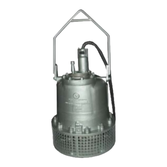
SUBMERSIBLE PUMPS
MODELS
S6B1-E95 460/3
and
S6B1-E95 575/3
THE GORMAN‐RUPP COMPANY D MANSFIELD, OHIO
www.grpumps.com
D
GORMAN‐RUPP OF CANADA LIMITED
ST. THOMAS, ONTARIO, CANADA
Printed in U.S.A.
e
2009 The Gorman‐Rupp Company
Advertisement
Table of Contents

Related Manuals for GORMAN-RUPP S6B1-E95 460/3


Summary of Contents for GORMAN-RUPP S6B1-E95 460/3
- Page 1 March 26, 2009 Rev. B 05‐15‐12 INSTALLATION, OPERATION, AND MAINTENANCE MANUAL WITH PARTS LIST SUBMERSIBLE PUMPS MODELS S6B1-E95 460/3 S6B1-E95 575/3 THE GORMAN‐RUPP COMPANY D MANSFIELD, OHIO www.grpumps.com GORMAN‐RUPP OF CANADA LIMITED ST. THOMAS, ONTARIO, CANADA Printed in U.S.A. 2009 The Gorman‐Rupp Company...
- Page 2 Register your new Gorman‐Rupp pump online at www.grpumps.com Valid serial number and e‐mail address required. RECORD YOUR PUMP MODEL AND SERIAL NUMBER Please record your pump model and serial number in the spaces provided below. Your Gorman‐Rupp distributor needs this information when you require parts or service. Pump Model: Serial Number:...
-
Page 3: Table Of Contents
TABLE OF CONTENTS INTRODUCTION ..........PAGE I - 1 SAFETY ‐... - Page 4 TABLE OF CONTENTS (continued) PARTS LISTS: Pump Assemblies ............PAGE E - 3 Terminal Housing and Cable Assemblies .
-
Page 5: Introduction
S SERIES PUMPS OM-06257 INTRODUCTION Thank You for purchasing a Gorman‐Rupp S Se RECORDING MODEL AND ries Pump. Read this manual carefully to learn SERIAL NUMBER how to safely install and operate your pump. Fail ure to do so could result in personal injury or dam Please record the pump model and serial number age to the pump. - Page 6 S SERIES PUMPS OM-06257 damage which could result from failure to follow the procedure. Hazards or unsafe practices which COULD NOTE result in minor personal injury or product or Instructions to aid in installation, operation, and property damage. These instructions de maintenance or which clarify a procedure.
-
Page 7: Safety - Section A
OM-06257 S SERIES PUMPS SAFETY - SECTION A This information applies to the S Series submersible motor driven pumps indi cated on the front cover of this manual. Before connecting any cable to the con Because pump installations are seldom trol box, be sure to ground the control identical, this manual cannot possibly box. - Page 8 S SERIES PUMPS OM-06257 position and locked out, or that the pow trician to troubleshoot, test and/or ser er supply to the control box has been vice the electrical components of this otherwise cut off and locked out, before pump. attempting to open or service the pump assembly.
-
Page 9: Installation - Section B
OM-06257 S SERIES PUMPS INSTALLATION - SECTION B GENERAL INFORMATION ratings on the control box and incoming pow Review all SAFETY information in Section A. e. Carefully read all tags, decals, and markings Since pump installations are seldom identical, this on the pump, and perform all duties indicated. -
Page 10: Pump Motor Specifications
OM-06257 S SERIES PUMPS equipment as outlined in the National to prevent liquid from wicking through the Electric Code. Follow all safety require cable and into the motor. ments. Failure to observe these require NOTE ments could result in injury or death to Refer to the performance curve in Maintenance personnel. -
Page 11: Positioning The Pump
OM-06257 S SERIES PUMPS Positioning the Pump The pump will operate if positioned on its side, but this is not recommended because the motor NOTE torque could cause the pump to roll during opera Before installing and operating the pump, check tion. -
Page 12: Electrical Connections
OM-06257 S SERIES PUMPS ting near the pump. The discharge line must be in sible to the operator, and located close enough to dependently supported to avoid strain and vibra the pump to avoid excessive voltage drop due to tion on the pump. cable length (see Pump Power Cable Connec... -
Page 13: Grounding Methods
OM-06257 S SERIES PUMPS be of the proper size and type to ensure an ade Table B‐3. Pump Voltage Requirements quate voltage supply to the pump. Voltage avail MAXIMUM NOMINAL MINIMUM PHASE VOLTAGE able at the motor must be within the range indi VOLTAGE VOLTAGE cated in Table B‐3. -
Page 14: Pump Power Cable Connections
OM-06257 S SERIES PUMPS c. Buried electrode: If rock or stone prevents this pump is high enough to cause inju embedding the full 8 foot (2,4 m) length of the ry or death. Obtain the services of a ground rod, bury it horizontally in a trench. qualified electrician to make all electri... -
Page 15: Control Box Specifications
OM-06257 S SERIES PUMPS Connect the pump power cable to the control box NOTE as shown in the wiring diagrams in the control box For reference, internal motor wiring connections manual. Use conduit or cable clamps to secure the are shown in Maintenance and Repair - Section power cable to the control box. -
Page 16: Wiring Diagrams
OM-06257 S SERIES PUMPS PUMP PUMP CONTROL BOX CONTROL BOX TO LEVEL CONTROL CIRCUIT TO LEVEL CONTROL CIRCUIT IN MAIN CONTROL BOX IN MAIN CONTROL BOX LIQUID LEVEL LIQUID LEVEL RANGE RANGE DEWATERING DEWATERING ON (FILLING) ON (FILLING) Figure B-4. Liquid Level Devices cluded with the option before making wir... -
Page 17: Operation - Section C
S SERIES PUMPS OM-06257 OPERATION - SECTION C GENERAL INFORMATION Review all SAFETY information in Section A. The pump motor and control box are not designed to be explosion‐proof. Do not operate in an explosive atmosphere. Any control box used to operate the This pump is designed to handle most pump must be approved by the Gor... -
Page 18: Impeller Rotation
OM-06257 S SERIES PUMPS or thermal protection, or if the pump is operated 4. Check the temperature before ser against a closed discharge valve for an extended vicing. period of time. 5. Vent the pump slowly and cau tiously 6. Refer to instructions in this manual before restarting the pump. -
Page 19: Starting, Stopping And Operational Checks
S SERIES PUMPS OM-06257 this pump is high enough to cause inju ry or death. Make certain that incoming power is off and locked out before inter changing motor leads. Never start the pump more than 6 times per hour. If the pump motor does not cool be tween starts, it will over‐heat, resulting in damage to the motor windings. -
Page 20: Cold Weather Preservation
OM-06257 S SERIES PUMPS COLD WEATHER PRESERVATION To avoid serious damage to the pump, check for unusual noises or excessive vi Do not attempt to thaw the pump by us bration while the pump is running. If noise ing a torch or other source of flame. This or vibration is excessive, stop operation could damage gaskets, O‐rings or heat and refer to the troubleshooting chart in the... -
Page 21: Draining Oil
S SERIES PUMPS OM-06257 month thereafter. Check the motor lubrication level Adding Oil any time the pressure relief valve is activated, and Refer to Table B-2 in INSTALLATION for oil ca replace the oil annually. pacities and positions for filling the seal cavity in your pump. - Page 22 OM-06257 S SERIES PUMPS Table C-1. Pump Oil Specifications Specifications: Type ......Premium high viscosity index, anti‐wear hydraulic oil Viscosity @ 100_F (38_C) .
-
Page 23: Troubleshooting - Section D
OM-06257 S SERIES PUMPS TROUBLESHOOTING - SECTION D Review all SAFETY information in Section A. NOTE Many of the probable remedies listed in the TROU BLESHOOTING CHART require use of electrical test instruments; for specific procedures, see ELECTRICAL TESTING at the end of the chart. TROUBLESHOOTING CHART TROUBLE POSSIBLE CAUSE... - Page 24 S SERIES PUMPS OM-06257 TROUBLESHOOTING CHART (cont'd) TROUBLE POSSIBLE CAUSE PROBABLE REMEDY Discharge head too high. Reduce discharge head or install MOTOR RUNS, BUT PUMP FAILS staging adaptor and additional TO DELIVER pump. RATED DIS Low or incorrect voltage. Measure control box voltage, both CHARGE.
- Page 25 OM-06257 S SERIES PUMPS ELECTRICAL TESTING 3. The pump submerged and running under full load. Make the electrical checks which follow to deter The voltage measured under each condition mine if pump malfunctions are being caused by must be the same. problems in the motor or in the motor cable.
- Page 26 S SERIES PUMPS OM-06257 the other test lead to each of the motor cable should be rechecked regularly. If resistance leads in turn. Note the readings. reads less than 1 megohm, insulation should be checked more closely and frequently. b. Readings will indicate resistance values in both the power cable and motor windings.If resistance reads infinity (1), insulation is c.
-
Page 27: Pump Maintenance And Repair - Section E
MAINTENANCE AND REPAIR OF THE WEARING PARTS OF THE PUMP WILL MAINTAIN PEAK OPERATING PERFORMANCE. STANDARD PERFORMANCE FOR PUMP MODELS S6B1-E95 460/3 AND S6B1-E95 575/3 Based on 70_F (21_C) clear water at sea level Contact the Gorman‐Rupp Company to verify per... - Page 28 S SERIES PUMPS OM-06257 SECTION DRAWING PARTS PAGE Figure E-1. S6B1-E95 460/3 And S6B1-E95 575/3 Pump Assemblies PAGE E - 2 MAINTENANCE AND REPAIR...
- Page 29 OM-06257 S SERIES PUMPS S6B1-E95 460/3 And S6B1-E95 575/3 Pump Assemblies Parts List (From S/N 1429736 Up) If your pump serial number is followed by an “N”, your pump is NOT a standard production model. Contact the Gorman‐Rupp Company to verify part numbers.
- Page 30 S SERIES PUMPS OM-06257 SECTION DRAWING Figure E-2. Terminal Housing And Cable Assembly PAGE E - 4 MAINTENANCE AND REPAIR...
- Page 31 OM-06257 S SERIES PUMPS Terminal Housing And Cable Assembly Parts List ITEM PART MAT'L PART NAME NUMBER CODE TERMINAL POST 38724-009 14100 TERMINAL COLLAR 10052 14100 HEAT‐SHRINK TUBE 31413-014 19530 T‐TYPE LOCKWASHER AK06 15991 RD HD MACH SCREW X0603 14990 TERMINAL 27214-058 TERMINAL WASHER...
- Page 32 S SERIES PUMPS OM-06257 used, disconnect the piping before attempting to PUMP AND SEAL DISASSEMBLY AND move the pump. REASSEMBLY Review all SAFETY information in Section A. Do not attempt to lift the pump by the motor power cable or the piping. Attach proper lifting equipment to the lifting Do not attempt to service the pump as...
- Page 33 OM-06257 S SERIES PUMPS disturbed. Repair gaskets and O‐rings are listed in dirt contamination. The presence of dirt or water the Parts List. could indicate a breakdown in the waterproof in tegrity of the motor cavity, probably due to poor gaskets or seals.
- Page 34 S SERIES PUMPS OM-06257 the vanes of the impeller. Screw the impeller knock place the diffuser on the cloth with the impeller side er (supplied with the pump) onto the rotor shaft. down. Use a drift pin or screwdriver to press on al ternate sides of the stationary seat until the station...
- Page 35 OM-06257 S SERIES PUMPS will result in premature leakage or reduced pump performance. It is strongly recommended that new gaskets and shaft seal assemblies be used during reassembly (see the parts lists for numbers). Most cleaning solvents are toxic and flammable.
- Page 36 S SERIES PUMPS OM-06257 ROTOR STATIONARY SHAFT SEAL SEAT ROTATING ELEMENT STATIONARY ELEMENT SPRING BELLOWS AND RETAINING ASSY SPRING RETAINER SEAL RETAINING RING STATIONARY O‐RING SEAL SEAT STATIONARY O‐RING ELEMENT DIFFUSER ROTATING ELEMENT BELLOWS AND RETAINING ASSY SPRING IMPELLER WASHER IMPELLER SHIM SET Figure E-3.
- Page 37 OM-06257 S SERIES PUMPS may not stay in the bellows retainer when turned NOTE upside down, place a small amount of grease at When pressing seal components onto the rotor equal spaces on the back of the element and posi shaft, use hand pressure only.
- Page 38 S SERIES PUMPS OM-06257 Be sure the impeller bore and the shaft are free of the suction head and add or remove adjusting oily film and completely dry. Do not apply lubri shims (7) as required. If necessary, the spacers (6) cants of any kind to the impeller bore or the tapered may also be removed.
- Page 39 OM-06257 S SERIES PUMPS Secure the pump in an upright position. Remove MOTOR DISASSEMBLY the deform locknuts (36) securing the terminal housing assembly (34) to the motor housing as Disassembly of the motor is rarely required except sembly (20). to replace the motor rotor, stator or bearings. Do not disassemble the motor unless it is necessary (Figure E-2) and a clean, well‐equipped shop is available.
- Page 40 S SERIES PUMPS OM-06257 To disconnect the power cable (13) from the termi and 39) from the motor housing as an assembly. If nal housing, pull the terminal plate (19) away from necessary, tap around the parting surfaces with a the terminal housing.
- Page 41 OM-06257 S SERIES PUMPS tation is rough or the bearing balls discolored, re place the bearings. The bearing tolerances provide a tight press fit Take care not to damage the stator end onto the shaft and a snug slip fit into the motor turns during removal from the motor hous...
- Page 42 S SERIES PUMPS OM-06257 bail to the motor housing. Make sure the bushings tilated area; free from excessive heat, (61) are in place when installing the hoisting bail. sparks, and flame. Read and follow all precautions printed on solvent contain MOTOR REASSEMBLY ers.
- Page 43 OM-06257 S SERIES PUMPS After the stator is fully and squarely seated on the NOTE motor housing shoulder, remove the expandable If a hot oil bath is used to heat the bearings, both the disc tool. Untape or remove the protective sleeve oil and the container must be absolutely clean.
- Page 44 S SERIES PUMPS OM-06257 After the bearings have been installed and allowed Using a three‐leg sling and lifting eyes in the inter to cool, check to ensure that they have not moved mediate flange holes, carefully lower the intermedi out of position in shrinking. If movement has oc ate over the shaft and lower bearing, guiding the curred, use a suitably sized sleeve and a press to studs in the bearing cap through the holes in the...
- Page 45 OM-06257 S SERIES PUMPS hardware (46 and 47); torque the nuts evenly in a ing (8) for ease of assembly. Slide the terminal cross sequence to 120 ft. lbs. (1440 in. lbs. or 16,6 gland, cable grip (11), gland bushing, terminal m.
- Page 46 S SERIES PUMPS OM-06257 terial has been noticeably compressed, it should housing connections. Use of unapproved be supplemented with two gaskets contained in sealing products will void the pump war the overhaul gasket kit (see Options listed in the ranty. Parts List manual).
- Page 47 OM-06257 S SERIES PUMPS 1 YELLOW - CONNECT TERMINAL TO GROUND INSIDE TERMINAL HOUSING WHITE (T1) 2 GREEN - TOGETHER IN ONE TERMINAL. CONNECT TERMINAL TO GROUND INSIDE TERMINAL HOUSING (T3) BLACK (T2) Figure E-6. Terminal Housing Wiring Connections Sealing Terminal Plate Connections Secure each cable lead as described in the pre...
- Page 48 S SERIES PUMPS OM-06257 terminal collar and lead connections. NOTE A .12 in. (3,05 mm) gap is required between the ter minal gland cap flange and the terminal housing When potting has been completed, leave the ter when tighten the nuts. minal plate assembly undisturbed until the potting material has cured.
- Page 49 OM-06257 S SERIES PUMPS cavity for its full duration first, then use the shutoff tor cavities. valve to maintain the motor cavity vacuum while testing the seal cavity. The motor cavity vacuum must be higher than the vacuum in the seal cavity Figure E-6 shows a simple schematic for setting to prevent separation of the seal faces or unseating up either a vacuum pump or a venturi/compressor...
- Page 50 S SERIES PUMPS OM-06257 Table E-2. Oil Quantity Pump Model Seal Cavity Motor Cavity 176 ounces (5,2 liters) 576 ounces (17 liters) Table E-3. Pump Oil Specifications Specifications: Type ......Premium high viscosity index, anti‐wear hydraulic oil Viscosity (SSU @ 104_F [40_C]) .
- Page 51 For Warranty Information, Please Visit www.grpumps.com/warranty or call: U.S.: 419-755-1280 Canada: 519-631-2870 International: +1-419-755-1352 GORMAN‐RUPP PUMPS...
Need help?
Do you have a question about the S6B1-E95 460/3 and is the answer not in the manual?
Questions and answers