Table of Contents
Advertisement
Quick Links
ACDEU
OM-06199-03
September 25, 2008
Rev. E 03‐09‐12
INSTALLATION, OPERATION,
AND MAINTENANCE MANUAL
WITH PARTS LIST
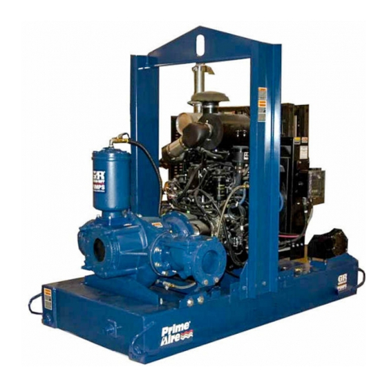
PA SERIES PUMP
MODEL
PA6C60-4045T
THE GORMAN‐RUPP COMPANY D MANSFIELD, OHIO
www.grpumps.com
D
GORMAN‐RUPP OF CANADA LIMITED
ST. THOMAS, ONTARIO, CANADA
Printed in U.S.A.
e
2008 The Gorman‐Rupp Company
Advertisement
Table of Contents

Subscribe to Our Youtube Channel
Related Manuals for GORMAN-RUPP PA6C60-4045T


Summary of Contents for GORMAN-RUPP PA6C60-4045T
- Page 1 September 25, 2008 Rev. E 03‐09‐12 INSTALLATION, OPERATION, AND MAINTENANCE MANUAL WITH PARTS LIST PA SERIES PUMP MODEL PA6C60-4045T THE GORMAN‐RUPP COMPANY D MANSFIELD, OHIO www.grpumps.com GORMAN‐RUPP OF CANADA LIMITED ST. THOMAS, ONTARIO, CANADA Printed in U.S.A. 2008 The Gorman‐Rupp Company...
- Page 2 Register your new Gorman‐Rupp pump online at www.grpumps.com Valid serial number and e‐mail address required. The engine exhaust from this product contains chemicals known to the State of California to cause cancer, birth defects or other reproductive harm. RECORD YOUR PUMP MODEL AND SERIAL NUMBER Please record your pump model and serial number in the spaces provided below.
-
Page 3: Table Of Contents
TABLE OF CONTENTS INTRODUCTION ..........PAGE I - 1 SAFETY ‐... - Page 4 TABLE OF CONTENTS (continued) PARTS LIST: Pump Model ............PAGE E - 3 Pump Assembly .
-
Page 5: Introduction
PA SERIES OM-06199 INTRODUCTION Thank You for purchasing a Gorman‐Rupp pump. The following are used to alert personnel to proce Read this manual carefully to learn how to safely dures which require special attention, to those install and operate your pump. Failure to do so which could damage equipment, and to those could result in personal injury or damage to the which could be dangerous to personnel:... -
Page 6: Safety - Section A
PA SERIES OM-06199 SAFETY ‐ SECTION A This information applies to Prime Aire damage the pump or endanger person Series pumps. Refer to the manual ac nel as a result of pump failure. companying the engine or power source before attempting to begin oper ation. - Page 7 OM-06199 PA SERIES heated pump. Vapor pressure within the pump can cause parts being disen gaged to be ejected with great force. Al low the pump to cool completely before Do not operate an internal combustion servicing. engine in an explosive atmosphere. When operating an internal combustion engine in an enclosed area, make sure exhaust fumes are piped to the outside.
-
Page 8: Installation - Section B
See Figure 1 for the approximate physical dimen some of the information such as mounting, line sions of this pump. OUTLINE DRAWING Figure 1. Pump Model PA6C60-4045T PREINSTALLATION INSPECTION a. Inspect the pump for cracks, dents, damaged threads, and other obvious damage. -
Page 9: Battery Installation
OM-06199 PA SERIES c. Carefully read all tags, decals, and markings POSITIONING PUMP on the pump assembly, and perform all duties indicated. Note that the pump shaft rotates in the required direction. Use lifting and moving equipment in good repair and with adequate capacity to prevent injuries to personnel or dam... -
Page 10: Suction And Discharge Piping
PA SERIES OM-06199 the brake and blocking the wheels before attempt lines are used, they should have adequate support ing to operate the pump. to secure them when filled with liquid and under pressure. Gauges The pump is drilled and tapped for installing dis If the pump has been mounted on a mov... -
Page 11: Sealing
OM-06199 PA SERIES Sealing air to escape from the liquid before it is drawn into the suction inlet. Since even a slight leak will affect priming, head, If two suction lines are installed in a single sump, and capacity, especially when operating with a the flow paths may interact, reducing the efficiency high suction lift, all connections in the suction line of one or both pumps. -
Page 12: Discharge Lines
PA SERIES OM-06199 Figure 2. Recommended Minimum Suction Line Submergence vs. Velocity DISCHARGE LINES Siphoning If the application involves a high discharge head, gradually close the discharge Do not terminate the discharge line at a level lower than that of the liquid being pumped unless a si throttling valve before stopping the pump. -
Page 13: Float Switch Installation
OM-06199 PA SERIES Float Switch Installation pipe is available, attach the float switch cable to the standpipe in the sump at the approxi The Float Switch autostart system employs either a mate desired liquid level. single or double float switch, where a bulb raises or lowers (floats) with the liquid level, thus activating b. -
Page 14: Operation - Section C
OM-06199 PA SERIES OPERATION - SECTION C Review all SAFETY information in Section A. cated (see LUBRICATION in MAINTENANCE AND REPAIR). Follow the instructions on all tags, labels and The pump will begin to prime upon startup. The air decals attached to the pump. in the suction line will be discharged from the educ... -
Page 15: Operation
OM-06199 PA SERIES AL'. After the engine starts and the unit is fully Liquid Temperature And Overheating primed, adjust the engine RPM until the desired The maximum liquid temperature for this pump is flow rate is achieved. 160_ F (71_C). Do not apply it at a higher operating temperature. -
Page 16: Stopping
OM-06199 PA SERIES vacuum suction gauge readings regularly to detect normal for bearings, and they can operate safely to strainer blockage. at least 180_F (82_C). Checking bearing temperatures by hand is inaccu Never introduce air or steam pressure into the rate. -
Page 17: Troubleshooting - Section D
OM-06199 PA SERIES TROUBLESHOOTING - SECTION D Review all SAFETY information in Section A. Before attempting to open or service the pump: 1. Familiarize yourself with this manual. 2. Shut down the engine, disconnect the positive battery cable and take precautions to ensure that the pump will remain inoperative. - Page 18 OM-06199 PA SERIES TROUBLE POSSIBLE CAUSE PROBABLE REMEDY Check strainer and clean if neces Strainer clogged. PUMP STOPS OR FAILS TO DELIVER sary. RATED FLOW OR Check and clean check valve. Discharge check valve clogged. PRESSURE (cont.) Suction intake not submerged at Check installation and correct proper level or sump too small.
-
Page 19: Preventive Maintenance
OM-06199 PA SERIES TROUBLE POSSIBLE CAUSE PROBABLE REMEDY BEARINGS RUN Bearing temperature is high, but Check bearing temperature regu TOO HOT within limits. larly to monitor any increase. Low or incorrect lubricant. Check for proper type and level of lubricant. Suction and discharge lines not prop... - Page 20 OM-06199 PA SERIES Preventive Maintenance Schedule Service Interval* Item Daily Weekly Monthly Semi‐ Annually Annually General Condition (Temperature, Unusual Noises or Vibrations, Cracks, Leaks, Loose Hardware, Etc.) Pump Performance (Gauges, Speed, Flow) Bearing Lubrication Seal Lubrication (And Packing Adjustment, If So Equipped) V‐Belts (If So Equipped) Air Release Valve Plunger Rod (If So Equipped) Front Impeller Clearance (Wear Plate)
-
Page 21: Pump Maintenance And Repair - Section E
PUMP MAINTENANCE AND REPAIR - SECTION E MAINTENANCE AND REPAIR OF THE WEARING PARTS OF THE PUMP WILL MAINTAIN PEAK OPERATING PERFORMANCE. STANDARD PERFORMANCE FOR PUMP MODEL PA6C60-4045T Based on 70_F (21_C) clear water at sea level with minimum suction lift. Since pump installations are seldom identical, your performance may be dif... - Page 22 OM-06199 PA SERIES PARTS PAGE SECTION DRAWING Figure 1. Pump Model PA6C60-4045T PAGE E - 2 MAINTENANCE & REPAIR...
- Page 23 OM-06199 PA SERIES Pump Model PA6C60-4045T PARTS LIST (From S/N 1416818 Up) ITEM PART MAT'L PART NAME NUMBER CODE PUMP END PA6C60-(SAE 4/10)--- POWER UNIT KIT 46143-081 BATTERY SEE OPTIONS PUMP MOUNTING KIT 48157-023 NOT SHOWN: G‐R DECAL GR-06 PRIME AIRE DECAL...
- Page 24 OM-06199 PA SERIES SECTION DRAWING VENTURI SYSTEMS Figure 2. 46143-081 Power Unit Kit PAGE E - 4 MAINTENANCE & REPAIR...
- Page 25 OM-06199 PA SERIES PARTS LIST 46143-081 Power Unit Kit ITEM PART NAME PART MAT'L ITEM PART NAME PART MAT'L NUMBER CODE NUMBER CODE J.D. 4045T ENGINE 29224-304 --- BALL/CHECK VALVE 26641-092 --- BASE/FUEL TANK 41553-006 24150 HOSE BARB FITTING 26523-446 --- LIFTING BAIL KIT 48274-804 --- RED PIPE BUSHING...
- Page 26 OM-06199 PA SERIES SECTION DRAWING Figure 3. PA6C60-(SAE 4/10) Pump Assembly PAGE E - 6 MAINTENANCE & REPAIR...
- Page 27 OM-06199 PA SERIES PA6C60-(SAE 4/10) Pump Assembly PARTS LIST ITEM PART MAT'L PART NAME NUMBER CODE 66F60-(SAE 4/10) PUMP END ASSEMBLY SEE FIGURE 4 6” CHECK VALVE KIT 48274-015 -CHECK VALVE 26642-126 -FLAPPER 26688-001 -COVER O‐RING 25152-377 -FLANGE GASKET 25113-036 PRIMING CHAMBER KIT 48275-005 NOT SHOWN:...
- Page 28 OM-06199 PA SERIES SECTION DRAWING Figure 4. 66F60-(SAE 4/10) Pump Subassembly PAGE E - 8 MAINTENANCE & REPAIR...
- Page 29 OM-06199 PA SERIES PARTS LIST 66F60-(SAE 4/10) Pump Subassembly ITEM PART NAME PART MAT'L ITEM PART NAME PART MAT'L NUMBER CODE NUMBER CODE PUMP CASING 38218-303 11010 HEX HD CAPSCREW B0806 15991 LOCK WASHER 15991 REPAIR ROTATING ASSY 44163-430 DRIVE ASSY 44162-159 BLIND FLANGE ASSY 42111-349...
- Page 30 OM-06199 PA SERIES SECTION DRAWING Figure 5. 44163-430 Repair Rotating Assembly PAGE E - 10 MAINTENANCE & REPAIR...
- Page 31 OM-06199 PA SERIES PARTS LIST 44163-430 Repair Rotating Assembly ITEM PART NAME PART MAT'L ITEM PART NAME PART MAT'L NUMBER CODE NUMBER CODE BRG HOUSING GSKT 38683-474 18000 IMPELLER 38615-092 11010 BRG SNAP RING S720 SEAL ASSY 46512-149 THRUST WASHER 31134-115 15000 SEAL PLATE...
- Page 32 OM-06199 PA SERIES SECTION DRAWING Figure 6. 48275-005 Priming Chamber Kit ITEM PART MAT'L PART NAME NUMBER CODE PRIMING CHAMBER ASSY 46112-709 PIPE BUSHING AP1608 11999 STREET ELBOW RS08 11999 BALL VALVE 26631-052 STUD C0809 15991 HEX NUT 15991 LOCK WASHER 15991 GASKET 38687-053...
- Page 33 OM-06199 PA SERIES SECTION DRAWING Figure 7. 46112-709 Priming Chamber Assembly PARTS LIST ITEM PART MAT'L PART NAME NUMBER CODE PRIMING VALVE 26664-007 -ORIFICE BUTTON 26688-021 HEX HD CAPSCREW B0806 15991 LOCKWASHER 15991 PRIMING VALVE GASKET 38683-657 19060 PRIMING CHAMBER 38343-020 10000 STRAINER ASSY...
- Page 34 OM-06199 PA SERIES SECTION DRAWING Figure 8. 44162-159 Drive Assembly ITEM PART MAT'L PART NAME NUMBER CODE COUPLING KIT 44165-016 BUSHING 24131-498 -KEY 24113-603 DRIVE FLANGE 38545-004 10000 IMPELLER SHAFT 38515-592 1706H LOCKWASHER 21171-536 SOC HD CAPSCREW BD0606 1/2 15991 SOC HD CAPSCREW 22644-220 HEX HD CAPSCREW...
- Page 35 OM-06199 PA SERIES PUMP AND SEAL DISASSEMBLY manual are performed only after estab lishing that neither personal safety nor AND REASSEMBLY pump integrity are compromised by such practices. Review all SAFETY information in Section A. Follow the instructions on all tags, label and de cals attached to the pump.
- Page 36 OM-06199 PA SERIES (1). Support the priming chamber assembly using Back Cover Plate and Wear Plate Removal a sling and a suitable lifting device. Remove the (Figure 4) hardware (6 and 7) and separate the priming chamber assembly, baffle (9) and gasket (8) from The wear plate (24) is easily accessible and may be the pump assembly.
- Page 37 OM-06199 PA SERIES pling must be replaced. To remove the ring, disen Turn gage the hardware (6 and 7) securing it to the fly Counterclockwise wheel. Move the pump end to a clean, well equipped shop area for further disassembly. Lathe Dog Arm Draining Oil From Seal Cavity “V”...
- Page 38 OM-06199 PA SERIES Impeller Removal Shaft and Bearing Removal and Disassembly (Figure 5) (Figure 5) When the pump is properly operated and main tained, the bearing housing should not require dis With the rotating assembly removed from the assembly. Disassemble the shaft and bearings pump casing, unscrew the impeller (1) in a coun...
- Page 39 OM-06199 PA SERIES flammable. Use them only in a well ven be cleaned and inspected in place. It is tilated area free from excessive heat, strongly recommended that the bearings sparks, and flame. Read and follow all be replaced any time the shaft and bear precautions printed on solvent contain...
- Page 40 OM-06199 PA SERIES Install the thrust washer (20) and secure the out crews in the center of the coupling must be posi board bearing (21) to the shaft with the snap ring tioned toward the drive end of the shaft. (19).
- Page 41 OM-06199 PA SERIES Do not use petroleum‐based lubricants, or any oth The seal is not normally reused because wear pat er substance which may soften or otherwise dam terns on the finished faces cannot be realigned age the rubber. during reassembly. This could result in premature failure.
- Page 42 OM-06199 PA SERIES RETAINER SEAL PLATE SPRING O‐RINGS IMPELLER SLEEVE O‐RING IMPELLER SHIMS IMPELLER SHAFT INTEGRAL SHAFT ROTATING SLEEVE ELEMENT BELLOWS SPRING CENTERING WASHER STATIONARY SEAT DRIVE BAND Figure 10. Seal Assembly the O‐ring down the shaft until it seats against the shaft shoulder.
- Page 43 OM-06199 PA SERIES Lubricate the O‐rings (16 and 25) with light grease and install them in the grooves in the wear plate and back cover. The shaft and impeller threads must be Clearance between the impeller and wear plate is adjusted using the four back cover nuts (31) and completely clean before reinstalling the im...
- Page 44 OM-06199 PA SERIES adjusting screws so the holes in the collars for the Install the cover O‐ring and secure the cover with locking screws align approximately with the holes the previously removed hardware. in the cover plate. Apply a small amount of light grease to the gasket Loosen the back cover nuts used to press the back to hold it in place and position it against the pump cover into the pump casing one full turn.
- Page 45 OM-06199 PA SERIES LUBRICATION NOTE The white reflector in the sight gauge must be posi (Figure 4) tioned horizontally to provide proper drainage. Seal Assembly Under normal conditions, drain the bearing hous Fill the seal cavity through the hole for the vented ing once each year and refill with clean oil.
- Page 46 For U.S. and International Warranty Information, Please Visit www.grpumps.com/warranty or call: U.S.: 419-755-1280 International: +1-419-755-1352 For Canadian Warranty Information, Please Visit www.grcanada.com/warranty or call: 519-631-2870 THE GORMAN‐RUPP COMPANY D MANSFIELD, OHIO GORMAN‐RUPP OF CANADA LIMITED ST. THOMAS, ONTARIO, CANADA...
Need help?
Do you have a question about the PA6C60-4045T and is the answer not in the manual?
Questions and answers