Table of Contents
Advertisement
Quick Links
Advertisement
Table of Contents

Summary of Contents for E+E Elektronik HUMLOG 10
- Page 1 HUMLOG 10 Manual Status V2 (12/2003)
-
Page 2: Table Of Contents
1 GENERAL 2 DISPLAY MODULE 3 HUMLOG 10 WITH INTERNAL SENSORS 4 HUMLOG 10 TSE FOR EXTERNAL SENSORS 5 HUMLOG 10 THC WITH INTERNAL SENSORS/WITHOUT DISPLAY 6 CHANGING THE SENSOR MODULE 7 CHANGING THE BATTERY 8 MOUNTING THE HUMLOG 10... -
Page 3: General
°C or °F, and the humidity in % (relative humidity) or in g/m³ (absolute humidity). The technical data of the HUMLOG 10 can be found on the internet : http://www.epluse.net Page 3 of 17... -
Page 4: Display Module
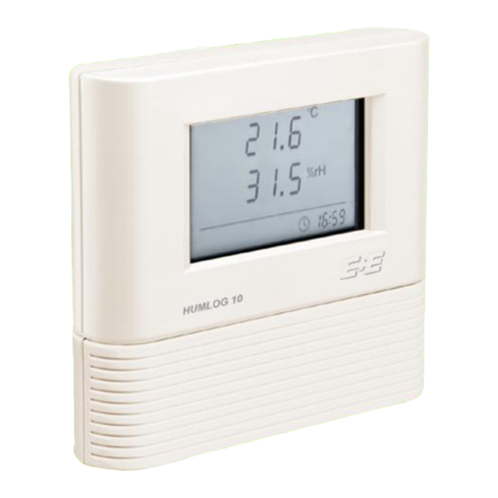
Manual HUMLOG 10 2 Display Module The HUMLOG 10 generally consists of two modules: a Display Module and a Sensor Module. The memory, real time clock and the microprocessor controller are located on the Display Module. Alarm Channel 1 Channel 1 Unit... - Page 5 Manual HUMLOG 10 Explanations concerning the Display operation: When a pre-set limit has been exceeded the alarm symbol of the corresponding channel flashes. Once an alarm has been recognised, the alarm symbol remains visible on screen in static form even if the limit is no longer exceeded. The alarm message can only be eliminated by selecting “Memory Readout”...
-
Page 6: Humlog 10 With Internal Sensors
Manual HUMLOG 10 3 HUMLOG 10 with Internal Sensors The sensors for temperature and relative humidity, the corresponding sensor adapters, and the serial interface (RS232) are located on this module. Illustration: Module with Internal Sensors Necessary calibration intervals are dependent on the environm ental conditions and the requirements of the permissible tolerance deviations. -
Page 7: Humlog 10 Tse For External Sensors
Manual HUMLOG 10 4 HUMLOG 10 TSE for External Sensors The connectors for the external sensors, the corresponding sensor adapters and the serial interface (RS232) are located on this module. Illustration: Module for External Sensors Either one or two temperature sensors or one to two combined temperature/humidity sensors can be connected here. - Page 8 Manual HUMLOG 10 If both socket positions are free, the indicat ion SENS appears in the upper line, and the first sensor can be connected to the left hand socket position. There are now 10 seconds available (Countdown on the display) to connect an optional second sensor to the right hand socket position.
-
Page 9: Humlog 10 Thc With Internal Sensors/Without Display
Manual HUMLOG 10 5 HUMLOG 10 THC with Internal Sensors/without Display General: the hardware of the HUMLOG10 compact is almost identical to the hardware of the HUMLOG10 with display. Two LEDs (a red and a green one) are used as a sub-stitute for the display to indicate the operation mode and the alarm. - Page 10 Before the HUMLOG starts recording, it can be activated or deactivated too via the on / off button (s. timing diagram). Button On Button Off Logger On Logger Off LED Green LED Red Timing Diagram: HUMLOG 10 THC in ring mode Page 10 of 17...
- Page 11 LED Green LED Red Timing Diagram: HUMLOG 10 THC in start-/stop mode The button should be kept pressed for approx. 1 sec. to start / stop the HUMLOG10. When activating the HUMLOG10, the green LED remains on during 3 sec. The red LED remains on during 3 sec.
- Page 12 As soon as the measured values have become normal again, both LEDs will flash to signal that an alarm came up. This can be reset by reading out the memory. Measuring value Set point LED Green LED Red Readout of data memory Timing Diagram: HUMLOG 10 THC alarms Page 12 of 17...
-
Page 13: Changing The Sensor Module
Manual HUMLOG 10 6 Changing the Sensor Module To change the Sensor Module please carefully remove the HUMLOG 10 back-plate with a screwdriver. The Sensor Module can now be detached from the display Module. Place the new Sensor Module on the display Module guide rail and push the two modules together until they engage. -
Page 14: Changing The Battery
The BAT indication now disappears and the measureme nt values are shown again on the display. The battery should be changed annually. Frequent data transfer with the PC and low sample rates reduces battery life. Illustration: Opening the HUMLOG 10 Illustration: Changing the battery to change the battery Page 14 of 17... -
Page 15: Mounting The Humlog
HUMLOG 10 8 Mounting the HUMLOG 10 The HUMLOG 10 can be used as a mobile and stationary data acquisition system. For stationary applications the HUMLOG 10 may only be mounted on a flat surface. In order to do this, please first remove the Sensor Module (see Changing the Sensor Module). -
Page 16: Switching On The Humlog
Manual HUMLOG 10 9 Switching on the HUMLOG 10 Just to take care of the battery the HUMLOG 10 the HUMLOG 10 is switched off during the delivery period. Commissioning: install and open the enclosed evaluation software SmartGraph on your PC (insert Disk 1/2 and run: setup_humlog10.exe) -
Page 17: Tips And Tricks
Frequent communication with the PC reduces battery life. Please use only the cable supplied for PC data transfer. Please avoid condensation on the sensor electronics and HUMLOG 10. For the entire information and further details regarding handling, configuration and evaluation of the data logger kindly have a look at the menu –...
Need help?
Do you have a question about the HUMLOG 10 and is the answer not in the manual?
Questions and answers