
Related Manuals for MOTU 828 Mk III Hybrid


Summary of Contents for MOTU 828 Mk III Hybrid
- Page 1 MOTU 828mk3 Hybrid ™ User Guide for Windows 1280 Massachusetts Avenue Cambridge, MA 02138 Business voice: (617) 576-2760 Business fax: (617) 576-3609 Web site: www.motu.com Tech support: www.motu.com/support...
- Page 2 The MOTU 828mk3 is equipped with a three-conductor cord and grounding type plug which has a grounding prong, approved by Underwriters' Laboratories and the Canadian Standards Association. This plug requires a mating three-conductor grounded type outlet as shown in Figure A below. If the outlet you are planning to use for the MOTU 828mk3 is of the two prong type, DO NOT REMOVE OR ALTER THE GROUNDING PRONG IN ANY MANNER.
-
Page 3: Table Of Contents
Contents Quick Reference: 828mk3 Front Panel Quick Reference: 828mk3 Rear Panel Quick Reference: MOTU Audio Console About the 828mk3 Packing List and System Requirements IMPORTANT! Run the 828mk3 Software Installer First Installing the 828mk3 Hardware MOTU Audio Console Front Panel Operation... - Page 4 Authorization Number on the outside of the box below the shipping address. That license agreement is a contract, and clicking “Accept” binds you and MOTU to This warranty does not apply if the equipment has been damaged by accident, all its terms and conditions.
-
Page 7: Quick Reference: Motu Audio Console
From the Windows Start menu, choose ■ Programs>MOTU>MOTU Audio Console. From within Cubase, go to the Device Setup ■ window, click the MOTU Audio ASIO list item and and click the Control Panel button. From within other applications, refer to their ■ documentation. -
Page 9: About The 828Mk3
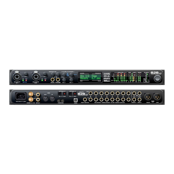
About the 828mk3 CHAPTER Overview ..........9 Two banks of optical digital I/O that provide 16 ■... - Page 10 THE 828MK3 REAR PANEL 28 inputs and 30 outputs All 828mk3 inputs and outputs can be used simul- The 828mk3 rear panel has the following taneously, for a total of 28 inputs and 30 outputs connectors: when operating at 44.1 or 48 kHz: Eight gold-plated, balanced quarter-inch (TRS) ■...
- Page 11 828mk3’s built-in monitor mixes. The included MOTU SMPTE Console™ software Main Outs includes a complete set of tools for generating and The main outs are equipped with 24-bit 192 kHz...
- Page 12 Individual 48 volt phantom Similarly, when the 828mk3 is operating at 96 kHz, power and a 20 dB pad can be supplied MOTU Audio Console lets you choose a word independently to each mic input. The Precision clock output rate of 48 kHz.
- Page 13 The Clock lights indicate the global sample rate (as CueMix FX also provides 7-band parametric EQ chosen in the MOTU Audio Console software). modeled after British analog console EQs, The LOCK and TACH LEDs provide feedback for featuring 4 filter styles (gain/Q profiles) to...
- Page 14 (included) allows you to keep tabs on the 828mk3’s processing resources. Each input, output and mix bus provides a send to the Classic Reverb processor, which then feeds reverb returns to mix busses and outputs, with a selectable split point between them to prevent send/return feedback loops.
-
Page 15: Packing List And System Requirements
If any of these items are not present in your ways to register. 828mk3 box when you first open it, please Visit www.motu.com to register online ■ immediately contact your dealer or MOTU. One 828mk3 Hybrid I/O rack unit ■ Fill out and mail the included product ■... - Page 16 P A C K I N G L I S T A N D S Y S T E M R E Q U I R E M E N T S...
-
Page 17: Important! Run The 828Mk3 Software Installer First
Also be sure to MOTU ASIO Driver ........18 read the Read Me file for installation assistance. - Page 18 CUEMIX FX This program provides a mixing console that gives you control over the 828mk3’s no-latency CueMix Figure 3-1: MOTU Audio Console gives you access to all of the settings FX on-board mixing and effects processing. For in the 828mk3 hardware.
-
Page 19: Installing The 828Mk3 Hardware
Syncing word clock devices......31 828mk3 Hybrid to one of its high-speed USB 2.0 Connecting multiple MOTU FireWire interfaces ..31 ports. - Page 20 If you are connecting via FireWire can be connected to a USB 2.0 hub along with USB 1 Before you begin, make sure your computer and 1.1 devices if necessary. The 828mk3 will not the 828mk3 are switched off. operate properly if it is connected to a USB 1.1 hub. 2 Plug one end of the 828mk3 FireWire cable Follow these instructions to determine whether (included) into the FireWire socket on the...
-
Page 21: Connect Audio Inputs And Outputs
If you are connecting via high-speed USB 2.0 CONNECT AUDIO INPUTS AND OUTPUTS 1 Before you begin, make sure your computer and The 828mk3 audio interface has the following the 828mk3 are switched off. audio input and output connectors: 2 Plug the flat “type A” plug of the 828mk3 USB 8 balanced, +4 dB quarter-inch analog outputs ■... - Page 22 The quarter-inch outputs are calibrated to produce in 1dB increments. You can also adjust trim in the a +4 dBu line level output signal. MOTU CueMix FX software. See “Input trim” on Quarter-inch analog input trims page 72. The quarter-inch inputs are calibrated to...
- Page 23 adjust these trims using CueMix FX, see “Input trim” on page 72. To adjust the trims using the front panel LCD: 1 Push the CHANNEL knob repeatedly until you see “I:” (which stands for Input) in the CHANNEL section of the LCD (Figure 4-7). 2 Turn the CHANNEL KNOB until you see the Figure 4-8: Setting the input trim for a TRS analog input pair.
- Page 24 When the 828mk3 is not connected directly to a For details about using the clock source setting and computer via FireWire, the sixteen optical output the MOTU Audio Console software in general, see channels can be programmed (via the CueMix FX chapter 5, “MOTU Audio Console” (page 35).
-
Page 25: Connect Midi Gear
If you would like to use a foot switch with your 828mk3, connect it to the PUNCH IN/OUT jack. Figure 4-10: Connecting a MIDI device to the 828mk3. See “Quick Reference: MOTU Audio Console” on One-way MIDI connections page 7 for information about how to program the... -
Page 26: A Typical 828Mk3 Setup
828mk3 front panel monitors foot switch MOTU 8pre and/or sends to other outputs (stage 8-channel other optical devices FX unit monitors, surround ADAT optical (in rack monitors, etc.) -
Page 27: Operating The 828Mk3 As A Converter
828mk3 supports 2x optical sample rates (88.2 or MOTU audio interface, such as a Traveler, 896mk3 96 kHz), you can also use both banks of connectors or even another 828mk3. The 828mk3 then serves as discussed in “ADAT optical operation at 88.2 or... -
Page 28: Making Sync Connections
— or make any sync connections. You can skip this perhaps no audio at all. section and proceed to “MOTU Audio Console” on page 35,where you’ll open MOTU Audio Console to confirm that the Clock Source setting is Internal... -
Page 29: Syncing To Smpte Timecode
Other digital audio device Windows computer running Cubase or Launch the MOTU SMPTE Console and specify the SMPTE Source, slaved to the 828mk3 other sample-accurate ASIO software which is the interface receiving the SMPTE timecode. Also, confirm that the Clock Source/Address is SMPTE/SMPTE. For details about the other settings, see chapter 10, “MOTU SMPTE Console”... -
Page 30: Syncing S/Pdif Devices
DAT deck or other SPDIF device With this setup, in the MOTU Audio Console window, choose Internal, or any other clock source setting except SPDIF. The DAT deck (or other SPDIF device) slaves to the 828mk3 via word clock for SPDIF transfers in both directions. -
Page 31: Syncing Word Clock Devices
Slaving to 2x and 1/2x word clock All MOTU FireWire audio interfaces that support 96 kHz operation have the ability to slave to a word clock signal running at either one half or one quarter of their current clock rate. - Page 32 Synchronizing multiple interfaces FireWire All connected MOTU FireWire interfaces get their clock from whatever you choose from the Clock Source menu in the General tab in MOTU Audio FireWire Console. When you connect multiple MOTU FireWire interfaces, all of their respective sync...
- Page 33 (#1, #2, #3, etc.) Interfaces are ID’d (given a number) by the order in which they are first Figure 4-23: All MOTU FireWire audio interfaces get their clock from a single master sync source on any connected 828mk3 (or other MOTU powered up after being connected.
- Page 34 I N S T A L L I N G T H E 8 2 8 M K 3 H A R D W A R E...
-
Page 35: Accessing The 828Mk3 Settings
Clock Source ......... 37 MOTU Audio ASIO from the ASIO Driver menu as Samples Per Buffer. -
Page 36: Motu Audio Console
MOTU Audio Console. the four available analog output pairs. Figure 5-1: MOTU Audio Console gives you access to all of the settings in the 828mk3 hardware. M O T U A U D I O C O N S O L E... -
Page 37: Clock Source
Clock Source Use this setting whenever you are recording input The Clock Source determines the digital audio from a DAT deck or other S/PDIF device into the clock that the 828mk3 will use as its time base. For 828mk3. It is not necessary in the opposite a complete explanation of synchronization issues, direction (when you are transferring from the see “Making sync connections”... -
Page 38: Samples Per Buffer
On the other hand, if you details, see “Syncing to SMPTE timecode” on increase the Samples Per Buffer, you reduce the load page 29 and chapter 10, “MOTU SMPTE Console” on your computer, freeing up bandwidth for (page 111). -
Page 39: Enable Pedal
or less, if your computer seems to be able to handle software (less efficient) option forces the 828mk3 them. If your host audio software has a processor multimedia driver to expose all channels as stereo meter, check it. If it starts getting maxed out, or if pairs, providing full MME support. -
Page 40: Main Outs Assign
Console to forget about an interface entirely, you’ll to send a final mix being played through the see a Forget button in MOTU Audio Console. Just 828mk3 back to the computer, where you could click the Forget button and MOTU Audio Console record it for mastering or archiving purposes. -
Page 41: Mic/Guitar Inputs
Front Panel Operation CHAPTER OVERVIEW For information about the many settings available The 828mk3 Hybrid offers complete front-panel for the mic/guitar inputs, see: programming via six rotary encoders and a 2x16 “The Inputs tab” on page 71 ■ backlit LCD display. All 828mk3 settings can be accessed via these front-panel controls. -
Page 42: Front Panel Operation
PHONES METERS AND STATUS LEDS From the factory, the PHONES jack (Figure 6-1) is The meters and LEDs (Figure 6-2) provide a discrete output at 44.1/48 kHz, but it can mirror complete status and metering information for all any other output pair (digital or analog) or serve as 828mk3 inputs and outputs. -
Page 43: Push-Button Rotary Encoders
PUSH-BUTTON ROTARY ENCODERS All of the knobs shown in Figure 6-3 are push- button digital rotary encoders. In many cases, you can either push the knob or turn it to make a setting or toggle the LCD display (depending on the encoder and setting). -
Page 44: 828Mk3 Setup Menu
LCD. It must be changed in turn it again to choose the desired preset slot you MOTU Audio Console instead. Or, you can disconnect the 828mk3 wish to save it to (1-16), and the push again to from the computer to change the Clock Source from the front panel. -
Page 45: Cuemix Menu
Type II — for 2x optical connection to MOTU The IN (inputs) menu ■ Push the CHANNEL button repeatedly until you products that are equipped with optical ports and see “I:” in the channel section of the LCD support 2x operation (Figure 6-6). - Page 46 channel strip in CueMix FX (Figure 9-3 on “ O: ” Indicates The current Access individual parameters the OUT channel. here, such as the frequency page 71), as well as the settings in the Channel tab (outputs) menu. setting for a band of EQ. (Figure 9-8 on page 75).
- Page 47 The MIX (Mixes) menu REVERB — these are the reverb send and return ■ Push the CHANNEL button repeatedly until you controls for the bus master fader. Access them with see “MIX 1” (or “MIX 2”, etc.) in the channel the PARAMETER knob.
-
Page 48: Inputs Menu
INPUTS MENU OUTPUTS MENU CHANNEL PAGE PARAM CHANNEL PAGE PARAM INPUTS INPUT PAIR OUTPUTS ENABLE mic 1-2 PHASE Main (global) COPY Analog 1-2 L-R/M-S (stereo or M/S) Analog 1-2 PASTE Analog 3-4 SWAP Analog 3-4, etc. RESET etc. WIDTH ENABLE TRIM (High-pass) SLOPE... -
Page 49: Mixes Menu
MIXES MENU STAND-ALONE OPERATION All settings, including all mix settings and global CHANNEL PAGE PARAM settings, are saved in the 828mk3’s memory, and MIXES MASTER ASSIGN they remain in effect even when the 828mk3 is not Mix 1 MUTE Mix 2 FADER connected to a computer. - Page 50 F R O N T P A N E L O P E R A T I O N...
-
Page 51: What Is Asio
WDM driver support is Run MOTU Audio Console ......51 provided instead. -
Page 52: Configuring Windows Audio Software
— or monitoring latency — that you hear when live audio is patched through your Figure 7-1: MOTU Audio Console gives you access to all of the settings 828mk3 hardware and host audio software. For in the 828mk3 hardware, including the clock source, sample rate and optical I/O enable/disable. -
Page 53: Choosing The Motu Audio Driver
Figure 7-2: Enabling the MOTU Audio ASIO driver in Pro Tools C O N F I G U R I N G W I N D O W S A U D I O S O F T W A R E... - Page 54 Console, click the Hardware Setup button. For information about the Buffer Size setting, see “Adjusting the audio I/O buffer” on page 61. Figure 7-3: Activating the MOTU Audio ASIO driver in Nuendo and Cubase. Figure 7-4: Enabling the MOTU Audio ASIO driver in Live.
- Page 55 Preferences window, choose Audio preferences from the menu and choose MOTU Audio ASIO from the Audio Card Driver menu as shown below. Figure 7-5: Enabling the MOTU Audio ASIO driver in Reason and Record. Reaper In Cockos Reaper, access the Preferences and click Devices under the Audio preferences.
- Page 56 Figure 7-9: Enabling the MOTU WDM driver in SONAR. 4 Next, in the Audio preferences section, choose Figure 7-10: Make sure you have chosen a 828mk3 input and output for the playback and recording timing master settings. Devices. 3 Additionally, if you are using the MOTU WDM 5 Check the 828mk3 Hybrid inputs and outputs driver, click the Wave Profiler button and run the...
-
Page 57: Working With 828Mk3 Inputs And Outputs
If you patch a live input (such as MIDI synthesizer) through a plug-in effect in your host audio Figure 7-12: Enabling the MOTU Audio ASIO driver in Sound Forge. software, you might hear a slight delay. There are Other audio software several ways to reduce this delay. -
Page 58: Synchronization
To trigger a the 828mk3 to the other components of your different set of keystrokes with the foot switch, visit system. MOTU Audio Console. (See “Enable Pedal” on page 39.) Synchronizing digital audio connections If you have devices connected to the 828mk3... - Page 59 Reducing Monitoring Latency CHAPTER OVERVIEW Monitoring live input....... . . 60 Monitoring latency is that slight delay you hear Adjusting the audio I/O buffer .
-
Page 60: Reducing Monitoring Latency
Instead, input is routed directly to an output, either with or without 828mk3-based effects processing (EQ, 1. Live input (from mic, guitar, etc.) enters the MOTU interface. 3. Mic signal is ‘patched thru’ back to the audio interface with host-based 2. - Page 61 Console, as shown in Figure 8-3 via the Samples Per Buffer setting. Figure 8-3: Lowering the ‘Samples Per Buffer’ setting in MOTU Audio Console reduces patch thru latency. But doing so increases the processing load on your computer, so keep an eye on the Perfor- mance Monitor in your host audio software.
- Page 62 Lower latency versus higher CPU overhead CUEMIX FX HARDWARE MONITORING The buffer setting has a large impact on the The 828mk3 has a more direct method of patching following things: audio through the system. This method employs the 828mk3’s CueMix FX digital mixer. When Patch thru latency ■...
- Page 63 Controlling CueMix DSP from within Cubase or Using CueMix FX Nuendo If your host audio software does not support direct To turn on CueMix in Cubase or Nuendo, enable hardware monitoring, you run the CueMix FX the Direct Monitoring check box in the Device software side-by-side with your audio software and Setup window.
- Page 64 R E D U C I N G M O N I T O R I N G L A T E N C Y...
-
Page 65: Cuemix Fx
CueMix FX CHAPTER OVERVIEW A 16-bus mixer with EQ, compression and reverb ..66 CueMix FX is a cross-platform software Advantages over host-based mixing and processing 66 application that provides graphic, on-screen CueMix FX installation ....... 67 control for the 828mk3 Hybrid’s flexible CueMix CueMix FX basic operation . -
Page 66: A 16-Bus Mixer With Eq, Compression And Reverb
A 16-BUS MIXER WITH EQ, COMPRESSION DSP resources for at least one band of parametric AND REVERB EQ and compression on every channel at 48 kHz. All 828mk3 inputs and outputs can be routed to the DSP resources are allocated dynamically and a on-board CueMix FX 16-bus (8 stereo bus) digital DSP meter in the CueMix FX software allows you mixer driven by hardware-based DSP with 32-bit... -
Page 67: Cuemix Fx Installation
CUEMIX FX INSTALLATION Many inputs to one output pair It might be useful to think of each mix bus as some CueMix FX is installed with the rest of your number of inputs all mixed down to a stereo output 828mk3 software. - Page 68 Each mix bus is independent Channel focus and settings Each mix bus has its own settings. Settings for one Click the focus button for a channel (Figure 9-1) to bus will not affect another. For example, if an input view channel-specific parameters in the Channel is used for one bus, it will still be available for other Settings section of the CueMix FX window busses.
-
Page 69: The Mixes Tab
THE MIXES TAB Assigning a mix bus output Choose the desired output pair for the mix bus Click the Mixes tab (Figure 9-2) to gain access to from the bus output menu (Figure 9-2). The bus the 828mk3’s eight stereo mix busses. The Mixes output menu displays all current available tab displays one mix bus at a time. - Page 70 Balance Bus mute The bus mute button (Figure 9-2) disables Balance works like the balance knob on some (silences) the mix. radios: turn it left and the right channel dims, turn it right and left channel dims. But the left channel Bus level meter always stays left and the right channel stays right.
-
Page 71: The Inputs Tab
THE INPUTS TAB record a completely unprocessed input signal, do The 828mk3 provides many features for managing not apply any changes to it in the Input tab. The analog and digital input signals. Some of these only exception to this is the reverb send, which features, such as the 828mk3’s digitally controlled simply splits the input signal and feeds a copy of it analog trims, are implemented in the analog... - Page 72 Mono/stereo pairing The controls in the EQ/Compression section of the Click the Mono button (Figure 9-3) if you would Inputs tab (Figure 9-3) let you edit EQ and like an input to be treated as a mono channel. If you compression settings within the context of the would like to work with it as one channel of a channel strip.
-
Page 73: The Outputs Tab
Reverb send Click the selector (Figure 9-4) for the desired EQ The input reverb send (Figure 9-3) feeds the input band, low-pass (LP) filter, high pass (HP) filter or signal to the 828mk3’s global reverb processor, compressor to view it across all channels. where it is merged with any other signals being fed to the reverb. - Page 74 then be fed back into the mixer at various return Monitor group assign Click the Monitor buttons (Figure 9-6) to toggle points, including the same output from which it whether the output pair is included in the Monitor was sent (discussed below). The output reverb group.
-
Page 75: The Channel Settings Section
THE CHANNEL SETTINGS SECTION The Channel tab The Channel tab (Figure 9-8) displays settings for The channel settings section in the CueMix FX input channels. Click any focus button in the window (Figure 9-1) displays three tabs for Inputs tab to view the Channel tab settings for the Channel, EQ and Dynamics settings for the channel. - Page 76 Stereo settings Reverb section Inputs that have been grouped as stereo pairs in the The Send in the reverb section (Figure 9-8) is the Inputs tab (Figure 9-3) provide two stereo modes same control as the reverb send in the Input tab (Figure 9-8): Normal and M/S.
- Page 77 The EQ tab display provides comprehensive control and visual The EQ tab (Figure 9-10) displays the EQ settings feedback of the EQ curve being applied. With for the input or output channel that currently has 64-bit floating point processing, the 828mk3 the focus.
- Page 78 Composite curve (white line): shows the overall Vintage EQ Quick reference Filter response display: Shows the response curve response curve of the current settings in the for the current settings. window. Vertical scale: Lets you zoom the vertical scale of Individual filter curve: Each filter has a color the filter response display.
- Page 79 Adjusting filters in the display Filter types Each filter has a handle, displayed as shown below Each filter can be independently set to one of four in Figure 9-12 (in the filter’s color), for adjusting its different filter types: I, II, III and IV. These, and the boost/cut and/or frequency: additional shelf filters for the LMF and HMF band, are discussed in the section “EQ filter styles”.
- Page 80 Type I Type II Figure 9-13: Type I EQ filter style. Figure 9-14: Type II EQ filter style. The Type I EQ filter has the least amount of Gain/Q The Type II EQ filter produces constant Q response interaction, providing the most precision and during boost or cut.
- Page 81 Type III Type IV Figure 9-16: Type IV EQ filter style. Figure 9-15: Type III EQ filter style. The Type IV EQ filter is a more extreme form of the The Type III EQ filter increases Q as boost is Type III filter.
- Page 82 Shelf filters response corresponds to a second order shelf, still with no overshoot. This is the same response as conventional parametric EQs. In some situations, this form of accurate, clean shelving can sound harsh, especially when compared to legacy analog EQs.
- Page 83 Overshoot tends to produce more of what one would expect to hear when applying shelving and Slope = 6 is therefore considered to be more musical than shelving without overshoot. This effect, which has gained tremendous popularity among audio engineers, was first made popular in original Neve series EQs and later in the SSL G series.
- Page 84 The Dynamics tab Compressor The Dynamics tab (Figure 9-21) displays the The Compressor (Figure 9-21) lowers the level of Dynamics processing settings for the input or the input when it is above the threshold. The output channel that currently has the focus. Click amount of attenuation is determined by the Ratio any focus button in the Inputs or Outputs tab to and the input level.
- Page 85 Peak/RMS modes mounted so that the emission of the panel In RMS mode the compressor uses RMS values (a modulates the resistance. An ELP consists of a thin computational method for determining overall layer of phosphorescent material sandwiched loudness) to measure the input level. In Peak mode, between two insulated electrodes to form a the compressor uses signal peaks to determine the capacitor.
- Page 86 It is precisely this self-adjusting behavior that The Meters tab The Meters tab (Figure 9-22) serves as a makes optical compressors the tool of choice for comprehensive meter bridge for all inputs, outputs smoothing out vocals, bass guitar and full- and mix busses in the 828mk3.
- Page 87 displaying an input meter). Click Pre to view levels Routing inputs, busses and outputs to the reverb processor before any input channel processing besides trim; The reverb processor is a single, independent unit click Post to view levels after all channel processing that provides stereo reverb.You can route multiple (EQ, compression, M/S decoding, L/R swap, etc.) signals to it from various points (sends) in the...
-
Page 88: The Monitor Group
Output types of spaces. The Size and Level parameters let When the Split Point is set to Output, the sends in you control the size of the room and the strength of Output tab become active and the returns in the the initial reflections. -
Page 89: Dsp Meter
(user dedicated mic in your control room and connect it defined). to a mic input on your MOTU audio interface. For Listenback, set up a dedicated listenback mic in the Monitor group meters... - Page 90 engaged. To completely silence all other CueMix Control room audio, turn them all the way down. attenuation Talkback only occurs when talkback or listenback is engaged. Audio playing back from disk (your host software) is not affected. Main outs Analog out 7-8 Talk dim Live room Headphone distribution amp...
-
Page 91: Shortcuts
The Mix1 return includes computer File menu item Alt-click bands and all inputs or outputs. applies to other MOTU interfaces products and has no effect on the 828mk3. Hardware follows CueMix Stereo Settings This File menu item applies to other MOTU interfaces products and has no effect on the 828mk3. -
Page 92: Edit Menu
Devices menu (Figure 9-27). DEVICES MENU Filter display options If you are working with more than one MOTU The Filter display options menu (Figure 9-10) audio interface product, this menu displays all provides several options for the EQ filter display: interfaces that are currently online. - Page 93 FFT display Spectrogram Choose Show FFT from the Filter display options Choose Show Spectrogram from the Filter display menu (Figure 9-10) to superimpose a real-time options menu (Figure 9-10) to superimpose a real- Fast Fourier Transform (FFT) frequency time spectrogram “waterfall” display in the measurement curve over the EQ filter display, as background of the EQ filter display, as demonstrated in Figure 9-30:...
- Page 94 Pausing the display Opening the FFT Analysis window Choose FFT Analysis from the Devices menu to The Pause button in the upper right corner of the open a new window with the filter EQ display for View section (Figure 9-33) allows you to freeze the detailed inspection and adjustment of the EQ filter, display at any time.
-
Page 95: Oscilloscope
In Zoom/Offset mode, Zoom sets the display zoom OSCILLOSCOPE The Oscilloscope (Figure 9-36) graphs the from 1x to 100x, where the number represents the zoom factor relative to the entire frequency range. amplitude of an audio signal over time. For example, when the horizontal zoom value is 1x, Amplitude is displayed on the y-axis and time is the entire frequency range from 10 to 24000 Hertz displayed on the x-axis. - Page 96 Horizontal controls (time axis) The Horizontal controls (Figure 9-38) configure Pause button the value range of the x-axis (time). Click and drag View menu the values up or down to set them, or double-click to return to the default value. There are two modes for the controls: Zoom/Offset Figure 9-37: View controls and Min/Max.
- Page 97 Waveform Recognition Trigger indicator The Waveform Recognition option searches Trigger menu through new audio data looking for a waveform Criteria check boxes which most resembles that which was previously displayed. The region where this takes place is a small window around the line marking time equals zero, denoted by the extra vertical graph lines Figure 9-40: Trigger settings surrounding it.
- Page 98 Trigger indicator Magnitude is enabled, the trigger will look for both The Trigger indicator (Figure 9-40 on page 97) +0.500 and -0.500. You will see a second blue line displays the state of the trigger, and also provides a appear in the display when Magnitude is enabled to way to manually interact with it.
- Page 99 Viewing transients such as drum hits To adjust the left and right edges of the If you loop a snare hit or other similar transient measurement area, click and drag the blue bars in audio clip and feed it through the oscilloscope, you the graph, or click and drag the blue numbers in can more or less “freeze”...
- Page 100 Monitoring control voltage output from Volta Building synthesizer patches MOTU’s Volta instrument plug-in for Mac OS X If you are building a synth patch on a synthesizer turns your audio interface into a control voltage...
-
Page 101: X-Y Plot
X-Y PLOT Situation Meter level X-Y Plot graph Mathematical The X-Y Plot window (Figure 9-43) graphs the relationship amplitude of a stereo audio signal on a two- Perfect correla- Diagonal line y = x tion going from dimensional grid. lower left to upper right: For each unit of time (i.e., each sample), the amplitude of the left channel is displayed on the x-... - Page 102 View controls shown in white and then fades to gray. To adjust the The View controls (Figure 9-44) provide several scale of this color/brightness change, see “Decay” options for the X-Y Plot display. on page 103. Axes Pause button The Axes control (Figure 9-44) sets the opacity of the grid displayed in the graph, from 100% (fully visible) down to 0% (fully hidden).
- Page 103 Using the X-Y Plot The X-Y Plot helps you “see” the width of the stereo field of a mix. It also helps you determine if a mix has issues with polarity, as follows: Figure 9-47: The Persistence controls. Activity on the X-Y Plot What it indicates Length Signal activity occurs mostly...
-
Page 104: Phase Analysis
PHASE ANALYSIS Opening the Phase Analysis Each 828mk3 interface has its own Phase Analysis The Phase Analysis window (Figure 9-49 on window. Choose the Phase Analysis item from the page 104) graphs frequency versus phase Devices menu under the desired interface. difference versus amplitude of a stereo signal on either rectangular or polar coordinates. - Page 105 Pausing the display and in polar coordinates, the radius from the The Pause button in the upper right corner of the center is frequency. With a linear scale, frequencies View section (Figure 9-50) allows you to freeze the are spaced evenly; in a logarithmic scale, each display at any time.
- Page 106 Axes Max delta theta The Axes control (Figure 9-50) sets the opacity of Max delta theta (Figure 9-55) only affects Line the grid displayed in the graph, from 100% (fully view (see “Line/Scatter” on page 105) and sets the visible) down to 0% (fully hidden). maximum difference in frequency between plot points in the line plot.
- Page 107 outside the critical frequency range of the In the polar view, any signal that falls on the instrument being recorded, you can avoid phase negative y axis (below zero) in polar view will be problems among the mic signals. canceled out when the signal is summed to mono. Tuning PA systems Checking for phase issues in stereo tracks The Phase Analysis window can also be used to...
-
Page 108: Tuner
Meter value: difference between the detected note TUNER and the detected frequency, in cents. Arrows: the direction in which the detected frequency needs to move to match the frequency of the detected note. The color of the arrows changes progressively in the same manner as the meter The Tuner window is an accurate and easy to use segments. -
Page 109: Talkback Menu
(last loaded or saved) configuration has a will hear on the headphone output, just like the check mark next to it. Phones setting in MOTU Audio Console. However, this menu provides one extra option that is Modifying a configuration exclusive to CueMix FX: Follow Active Mix. - Page 110 Enabled that is not currently being displayed, CueMix FX Check this menu item to turn on control surface will jump to the appropriate tab to display the operation of CueMix FX. Uncheck it to turn off control you are adjusting. control surface support.
-
Page 111: Motu Smpte Console
To resolve the 828mk3 to SMPTE time code, MOTU SMPTE Console ......111 choose the SMPTE / SMPTE setting in the Clock/ Address menu. -
Page 112: Reader Section
detect and switch to the incoming frame rate, Freewheel Address Freewheeling occurs when there is a glitch or except that it cannot distinguish between 30 fps drop-out in the incoming time code for some and 29.97 fps time code, or 23.976 and 24 fps time reason. -
Page 113: Generator Section
“Syncing to SMPTE timecode” on page 29. Make The Tach light blinks once per second when the sure the Clock Source setting in the MOTU Audio 828mk3 is generating SMPTE time code. Console window is set to SMPTE. Also, make sure that you’ve connected an LTC input signal to an... - Page 114 M O T U S M P T E C O N S O L E...
-
Page 115: Troubleshooting
Clicks and pops due to hard drive problems 828mk3 software and choose only to install the If you have checked your clock settings and you are MOTU FireWire ASIO driver, not the WDM still getting clicks and pops in your audio, you may Driver. Restart again. - Page 116 If you are unable, with your dealer’s help, to solve Check to make sure you have the desired optical problems you encounter with the 828mk3 system, inputs and/or outputs enabled in the MOTU Audio you may contact our technical support department Console.
- Page 117 Configure interface ASIO software installation Connecting multiple 828mk3s 7, 39 Legacy MME (Wave) summary of features Control Surfaces menu MIDI tab (MOTU Audio Console) Controller Wave driver connecting 67, 89 meter Word Clock In setting Converter mode resources 66, 89...
- Page 118 Forget button 33, 40 ASIO driver LCD display Freewheel Audio System Level meter address bit resolution 7, 35 clock MOTU Audio Console monitor group infinite 112, 113 MOTU SMPTE Console Leveler 84, 85 Frequency Lightpipe 2x mode Front panel Normal...
- Page 119 latency 38, 62 System requirements Peak minimum S/MUX Peak mode recommended computer S/PDIF Peak/Hold Time clock source setting 12, 39 Pedal connection configuring TACH 5, 13 lights Cubase light (SMPTE Console) 6, 11 optical jack Talkback Nuendo button (Channel tab) sync Pedal A button (Outputs tab)
- Page 120 I N D E X...
Need help?
Do you have a question about the 828 Mk III Hybrid and is the answer not in the manual?
Questions and answers