
Related Manuals for MOTU UltraLite- mk3


Summary of Contents for MOTU UltraLite- mk3
- Page 1 UltraLite ™ User Guide for Mac 1280 Massachusetts Avenue Cambridge, MA 02138 Business voice: (617) 576-2760 Business fax: (617) 576-3609 Web site: www.motu.com Tech support: www.motu.com/support...
- Page 2 Authorization Number on the outside of the box below the shipping address. That license agreement is a contract, and clicking “Accept” binds you and MOTU to This warranty does not apply if the equipment has been damaged by accident, all its terms and conditions.
-
Page 3: Table Of Contents
Contents Quick Reference: UltraLite-mk3 Front Panel Quick Reference: UltraLite-mk3 Rear Panel Quick Reference: MOTU Audio Setup About the UltraLite-mk3 Packing List and Mac System Requirements Installing the UltraLite-mk3 Hardware Installing the UltraLite-mk3 Mac Software MOTU Audio Setup UltraLite-mk3 Front Panel Operation... -
Page 7: Quick Reference: Motu Audio Setup
UltraLite-mk3 only, back into the computer. Click the General tab to access these settings. Check this option if you would like the MOTU Audio Setup icon to appear in the application dock as soon as a MOTU FireWire interface is detected (switched on, plugged in, etc.) -
Page 9: About The Ultralite-Mk3
About the UltraLite-mk3 CHAPTER Overview ..........9 RCA S/PDIF digital I/O at sample rates up to ■... - Page 10 Analog One combo XLR/TRS mic/instrument input ■ All six quarter-inch analog inputs are equipped RCA S/PDIF in/out ■ with 24-bit 192 kHz A/D converters. All eight analog outputs have 24-bit 192 kHz D/A MIDI IN and MIDI OUT jacks ■ converters.
-
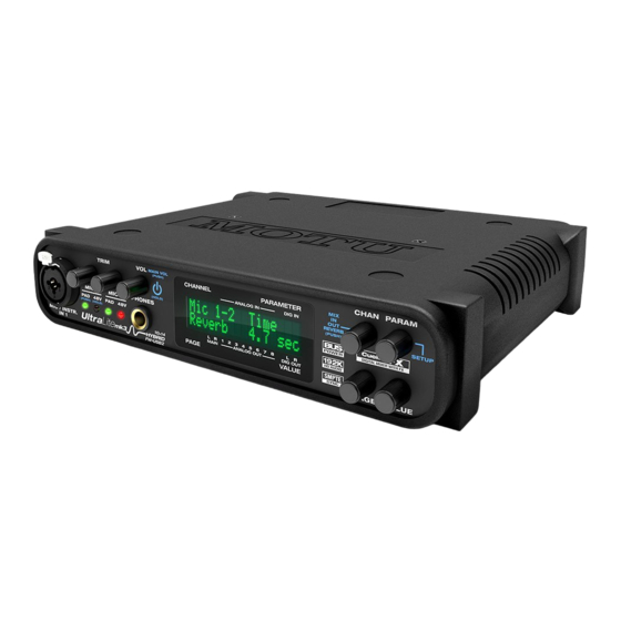
Page 11: The Ultralite-Mk3 Front Panel
The second jack can be used to daisy chain 16-BIT AND 24-BIT RECORDING multiple interfaces — up to four MOTU FireWire The UltraLite-mk3 system handles all data with a interfaces — on a single FireWire bus. It can also be 24-bit signal path, regardless of the I/O format. -
Page 12: Audiodesk
4 filter styles (gain/Q profiles) to The UltraLite-mk3 system is fully integrated with effectively cover a wide range of audio material. MOTU’s award-winning Digital Performer audio Low-pass and high-pass filters are also supplied sequencer software package. with slopes that range from 6 to 36 dB. The EQ OTHER HOST AUDIO SOFTWARE employs extremely high precision 64-bit floating... -
Page 13: Packing List And Mac System Requirements
If any of these items are not present in your two ways to register. UltraLite-mk3 box when you first open it, please Visit www.motu.com/register ■ immediately contact your dealer or MOTU. One UltraLite-mk3 I/O rack unit ■ Fill out and mail the included product ■... - Page 14 P A C K I N G L I S T A N D M A C S Y S T E M R E Q U I R E M E N T S...
- Page 15 A typical UltraLite-mk3 setup ......21 An example setup for computer-based mixing/FX. Connecting multiple MOTU FireWire interfaces ..22 Connect additional UltraLites or other audio...
-
Page 16: Installing The Ultralite-Mk3 Hardware
fine-tuned adjustments in precise 1dB ☛ Make absolute sure to align the flat side of the increments. You can also adjust trim in the MOTU FireWire plug properly with the flat side of the CueMix FX software. See “Input trim” on page 69. - Page 17 Three-way pad CueMix FX software to adjust the input trim. To The XLR jack is equipped with a three-way pad, so adjust these trims using CueMix FX, see “Input “hot” signals are best connected via an XLR cable trim” on page 69. To adjust the trims using the so that you can use the pad switch.
-
Page 18: Connect Midi Gear
Separate main outs One-way MIDI connections The main outputs operate as an independent pair MIDI devices that do not receive MIDI data, such (they don’t share signal with any other output as a dedicated keyboard controller, guitar pair). In a standard studio configuration, the main controller, or drum pad, only need Connection B outs are intended for a pair of studio monitors, but shown in Figure 3-4. -
Page 19: Connecting And Syncing S/Pdif Devices
CONNECTING AND SYNCING S/PDIF 6-pin FireWire connectors DEVICES The UltraLite-mk3 can only draw power over the DAT decks and other devices with S/PDIF digital FireWire bus from a 6-pin to 6-pin cable, or a 6-pin I/O will sync to the UltraLite-mk3 in via the to 9-pin (FireWire B) cable. - Page 20 PCMCIA or ExpressCard slot adapters — If you any standard 8-18 volt, 12 watt DC power supply ■ plan to connect the UltraLite-mk3 to a PC card with any polarity (tip positive or negative), and FireWire adapter (inserted in the PC card slot in amperage as shown below.
-
Page 21: A Typical Ultralite-Mk3 Setup
A TYPICAL ULTRALITE-MK3 SETUP latency monitoring to listen to what you are Here is a typical UltraLite-mk3 studio setup. This recording via the main outs, headphone outs, or rig can be operated without an external mixer. All any other output pair. You can control monitoring mixing and processing can be done in the either from the front panel or from the included computer with audio software. -
Page 22: Connecting Multiple Motu Firewire Interfaces
CONNECTING MULTIPLE MOTU FIREWIRE INTERFACES You can daisy-chain up to four MOTU FireWire interfaces on a single FireWire bus, with the restrictions described in the following sections. Most computers have only one built-in FireWire bus (even if it supplies multiple FireWire sockets). - Page 23 Connecting other MOTU FireWire interfaces UltraLite-mk3 and other FireWire devices to it. All You can add an original MOTU 828 to the end of a FireWire daisy chain (because the 828 has only one interfaces will remain resolved to each other via the master interface.
- Page 24 ExpressCard adaptor or PCI card allow you to add a second FireWire bus to your computer. In may be possible to add additional MOTU FireWire interfaces connected to such a third-party product, depending on the performance of the product and the performance of your host computer.
-
Page 25: Installing The Ultralite-Mk3 Mac Software
More specifically, MOTU SMPTE Console ....... 27 we use Core Audio to refer to Mac OS X’s standard... - Page 26 CoreMIDI and Audio MIDI Setup CoreMIDI is the “under-the-hood” portion of Mac OS X that handles MIDI services for MIDI hardware and software. CoreMIDI provides many universal MIDI system management features, including MIDI communication between your UltraLite-mk3 FireWire interface and all CoreMIDI compatible software.
- Page 27 UltraLite-mk3 to SMPTE time code, and to generate SMPTE for striping, regenerating or slaving other devices to the computer. For details, see chapter 12, “MOTU SMPTE Console” (page 91). Figure 4-3: Connecting devices to the UltraLite-mk3. In this example, a controller keyboard is connected to the UltraLite-mk3’s MIDI IN, and...
- Page 28 I N S T A L L I N G T H E U L T R A L I T E - M K 3 M A C S O F T W A R E...
-
Page 29: Accessing The Ultralite-Mk3 Settings
Default Stereo Input/Output......31 menu. Then click the MOTU Audio ASIO item in Phones..........32 the list and click the Control Panel button. -
Page 30: Motu Audio Setup
The following sections briefly discuss each clock source setting. Figure 5-1: MOTU Audio Setup gives you access to all of the settings in the UltraLite-mk3 hardware. M O T U A U D I O S E T U P... -
Page 31: Default Stereo Input/Output
SMPTE time code (LTC) being received via the UltraLite-mk3’s quarter-inch SMPTE input jack. For details, see “Syncing to SMPTE time code” on page 94and chapter 12, “MOTU SMPTE Console” (page 91). Built-in Audio Choose this setting to resolve the UltraLite-mk3 to your Mac’s built-in audio. -
Page 32: Phones
Choose becomes available Main Out 1-2 if you’d like the headphone output to Check this option if you would like the MOTU match the main outs. Choose Phones if you would Audio Setup icon to appear in the application dock... -
Page 33: Enable Pedal
Figure 5-4: UltraLite-mk3 channel names as they appear in Digital Performer. Enable Pedal This setting applies to other MOTU FireWire audio interfaces, but it does not apply to the UltraLite-mk3. M O T U A U D I O S E T U P... - Page 34 M O T U A U D I O S E T U P...
-
Page 35: Push-Button Rotary Encoders
UltraLite-mk3 Front Panel Operation CHAPTER OVERVIEW POWER SWITCH The UltraLite-mk3 offers complete front-panel Push the VOL knob to power on the programming via four rotary encoders and a 2x16 UltraLite-mk3. Push in and hold the VOL knob to backlit LCD display. All UltraLite-mk3 settings can turn it off. -
Page 36: Ultralite-Mk3 Front Panel Operation
PHONES MAIN OUT VOLUME From the factory, the PHONES jack (Figure 6-1) is Push the VOL knob twice to view and control the a discrete output at 44.1/48 kHz, but it can mirror volume of the main outs on the rear panel. any other output pair (digital or analog) or serve as its own independent output. -
Page 37: Multi-Function Lcd Display
Push the PARAM knob to cycle the LCD among setting cannot be changed from the front-panel LCD. It must be four global display modes: changed in MOTU Audio Setup instead. Or, you can disconnect the UltraLite-mk3 from the computer to change the Clock Source from the front panel. -
Page 38: Cuemix Menu
CUEMIX MENU wish to save it to (1-16), and the push again to To access the CUEMIX menu, push the PARAM confirm the save. To cancel the save operation at knob until you see CUEMIX displayed in the LCD. any time, turn the PARAM knob. This menu displays the settings for the Load Preset UltraLite-mk3 CueMix FX mixer. - Page 39 The IN (inputs) menu to jump to the next “section” of parameters or to Push the CHANNEL button repeatedly until you jump back to the beginning of the list. This is see “I:” in the channel section of the LCD roughly the equivalent of moving through the (Figure 6-6).
- Page 40 The OUT (Outputs) menu The MIX (Mixes) menu Push the CHANNEL button repeatedly until you Push the CHANNEL button repeatedly until you see “O:” in the channel section of the LCD see “MIX 1” (or “MIX 2”, etc.) in the channel (Figure 6-7).
-
Page 41: Inputs Menu
INPUTS MENU REVERB — these are the reverb send and return ■ controls for the bus master fader. Access them with CHANNEL PAGE PARAM the PARAMETER knob. INPUTS INPUT PAIR mic 1-2 PHASE Individual channels — once you scroll past ■... -
Page 42: Outputs Menu
OUTPUTS MENU MIXES MENU CHANNEL PAGE PARAM CHANNEL PAGE PARAM OUTPUTS ENABLE MIXES MASTER ASSIGN Main (global) COPY Mix 1 MUTE Analog 1-2 PASTE Mix 2 FADER Analog 3-4, etc. RESET etc. COPY PASTE ENABLE RESET (High-pass) SLOPE FREQ REVERB SEND RETURN ENABLE... -
Page 43: Digital Performer
UltraLite-mk3 settings, open MOTU Audio Setup. clock source, but to access all of the UltraLite-mk3 For complete details about the UltraLite-mk3 settings, open MOTU Audio Setup, as shown in settings, see chapter 5, “MOTU Audio Setup” Figure 5-1 on page 30. - Page 44 S/PDIF devices” on page 19. one of its output pairs. Use the Return Assign menu in MOTU Audio Setup to choose which output pair If you are slaving the UltraLite-mk3 and Digital you would like to hear on this return. This can be Performer to SMPTE time code via the used, for example, to record back a final stereo mix...
-
Page 45: Working With Ultralite-Mk3 Inputs And Outputs
“Reducing Monitoring Latency” (page 57). WORKING WITH ULTRALITE-MK3 INPUTS AND OUTPUTS WORKING WITH CUEMIX FX MIXING AND Once you’ve enabled the MOTU FireWire Audio EFFECTS driver as explained earlier in “The UltraLite-mk3 The UltraLite-mk3 provides powerful external settings” on page 43, UltraLite-mk3 audio inputs mixing, EQ, compression and reverb, which you and outputs will appear in Digital Performer’s... - Page 46 D I G I T A L P E R F O R M E R...
-
Page 47: Audiodesk
For complete details about the UltraLite-mk3 clock source, but to access all of the UltraLite-mk3 settings, see chapter 5, “MOTU Audio Setup” settings, open MOTU Audio Setup, as shown in (page 29). The following sections provide a brief Figure 5-1 on page 30. - Page 48 Use the Return Assign menu in If you are slaving the UltraLite-mk3 and MOTU Audio Setup to choose which output pair AudioDesk to SMPTE time code via the you would like to hear on this return. This can be UltraLite-mk3 itself, choose SMPTE and follow the used, for example, to record back a final stereo mix...
- Page 49 EQ, compression and reverb, which you WORKING WITH ULTRALITE-MK3 INPUTS AND OUTPUTS can operate hand-in-hand with AudioDesk’s Once you’ve enabled the MOTU FireWire Audio complete mixing environment. For example, the driver as explained earlier in “The UltraLite-mk3 UltraLite-mk3 can serve as a monitor mixer settings”...
- Page 50 Digital Performer, which offers pretty much all of the same features as AudioDesk, along with powerful, state-of-the-art MIDI sequencing. Talk to your authorized MOTU dealer for details about upgrading from AudioDesk to Digital Performer. A U D I O D E S K...
-
Page 51: Installing The Ultralite-Mk3 Mac Os X Drivers
Preparing MIDI input and output ....51 Run MOTU Audio Setup ......51 Choosing the MOTU FireWire Core Audio driver . -
Page 52: Other Mac Os X Software
UltraLite-mk3 that matches the signal of one of its output pairs. Use the Return Assign menu in MOTU Audio Setup to choose which output pair you would like to hear on this return. This can be used, for example, to record back a final stereo mix... - Page 53 Live In Soundtrack Pro, access the preferences window, In Ableton Live, access the preferences window and click the Recording tab and choose MOTU click the Audio tab. Choose CoreAudio from the UltraLite-mk3 from the Input and Monitor menu as Driver Type menu. Choose the MOTU UltraLite-mk3 from the Input Audio Device and shown below in Figure 9-3.
-
Page 54: Working With Ultralite-Mk3 Inputs And Outputs
For other audio applications, the procedure is window, choose Audio preferences from the menu similar to that shown above. Consult your owner’s and choose MOTU UltraLite-mk3 from the Audio manual for further information. Output menu as shown below in Figure 9-6. For... -
Page 55: Number Of Channels
Outputs are listed in this order: several ways to reduce this delay. For details, see chapter 10, “Reducing Monitoring Latency” Output Channels List position (page 57). Main WORKING WITH CUEMIX FX MIXING AND Analog 3-10 EFFECTS SPDIF 11-12 The UltraLite-mk3 provides powerful external mixing, EQ, compression and reverb, which you Phones 13-14... - Page 56 O T H E R M A C O S X S O F T W A R E...
- Page 57 Reducing Monitoring Latency CHAPTER OVERVIEW It is important to note that monitoring delay has no Monitoring latency is that slight delay you hear effect on when audio data is recorded to disk or when you run an input signal through your host played back from disk.
-
Page 58: Reducing Monitoring Latency
Instead, input is routed directly to an output, either with or without UltraLite-mk3-based effects processing (EQ, compression or reverb). See 1. Live input (from mic, guitar, etc.) enters the MOTU interface. 3. Mic signal is ‘patched thru’ back to the audio interface with reverb or other 2. - Page 59 Digital Performer or AudioDesk manual for information about the Host Buffer Multiplier setting. 1. Live input (from mic, guitar, etc.) enters the MOTU interface. 3. Mic signal is mixed with the 2. CueMix FX immediately patches the live main outs, and you can...
- Page 60 How responsive the transport controls are in ■ AudioDesk, Digital Performer or other audio software The buffer setting presents you with a trade-off between the processing power of your computer and the delay of live audio as it is being patched through your software.
- Page 61 Effects processing and automated mixing From within your host audio software (if it ■ Reducing latency with the buffer size setting has supports direct hardware monitoring) another benefit: it lets you route live inputs through You can even use both methods simultaneously. the real-time effects processing and mix automation of your audio software.
- Page 62 Controlling CueMix FX from within AudioDesk 3 From the Studio menu, choose Audio Patch or Digital Performer Thru, and choose any monitoring mode except Off. To turn on CueMix FX in AudioDesk and Digital Performer: Once enabled, CueMix FX monitoring is tied with Digital Performer or AudioDesk’s Audio Patch 1 From the Setup menu, choose Configure Audio Thru feature: when you record-enable a track, the...
-
Page 63: Cuemix Fx
CueMix FX CHAPTER OVERVIEW A 16-BUS MIXER WITH EQ, COMPRESSION AND REVERB CueMix FX is a cross-platform software All UltraLite-mk3 inputs and outputs can be application that provides graphic, on-screen routed to the on-board CueMix FX 16-bus (8 control for the UltraLite-mk3’s flexible CueMix FX stereo bus) digital mixer driven by hardware-based on-board mixer and effects processing. -
Page 64: Advantages Over Host-Based Mixing And Processing
Each input, output and mix bus provides a send to CueMix mixing and effects processing imposes ■ the Classic Reverb processor, which then feeds no processor drain on the computer’s CPU. reverb returns to mix busses and outputs, with a CueMix routing can be maintained ■... -
Page 65: Cuemix Fx Basic Operation
CUEMIX FX BASIC OPERATION processor. These settings are applied to the signal Here is a brief overview of the CueMix FX mixer. before it goes anywhere else (to a mix bus or the computer). Eight stereo mix busses CueMix provides eight stereo mix busses: Bus 1, Output channels Bus 2, Bus 3, and so on. -
Page 66: The Mixes Tab
THE MIXES TAB Assigning a mix bus output Click the Mixes tab (Figure 11-2) to gain access to Choose the desired output pair for the mix bus from the bus output menu (Figure 11-2). The bus the UltraLite-mk3’s eight stereo mix busses. The output menu displays all current available Mixes tab displays one mix bus at a time. - Page 67 Bus mute page 72). Clicking the mix bus master fader focus The bus mute button (Figure 11-2) disables button brings the assigned output into focus, if (silences) the mix. there is one. Bus level meter Input pan section The bus level meter, which is post-fader, shows you The input pan knob (Figure 11-2) pans the input the output for the mix’s output.
-
Page 68: The Inputs Tab
THE INPUTS TAB Signal flows from top to bottom Settings in each Input tab channel strip are The UltraLite-mk3 provides many features for generally applied to the signal in order from top to managing analog and digital input signals. Some of bottom. - Page 69 are grouped in odd/even pairs (mic 1-2, Analog Channel Section of the CueMix FX window 1-2, 3-4, etc.) Stereo pairs appear as a single (Figure 11-1). This section even provides graphical channel strip in the CueMix FX mixer (in all tabs). editing of EQ curves and the compressor graph, allowing you to click and drag directly on the Invert phase...
-
Page 70: The Outputs Tab
then be fed back into a mix or output pair. The send Compressor Compressor Compressor graph meter selector occurs after all other settings in the input channel strip (phase invert, EQ, compression, etc.) THE OUTPUTS TAB The Outputs tab (Figure 11-6) lets you apply EQ, dynamics and reverb to any output pair, just before the signal leaves the UltraLite-mk3. - Page 71 Output reverb send/return Talkback/Listenback The output reverb send (Figure 11-6) feeds the Click the Talkback or Listenback buttons signal for the output to the UltraLite-mk3’s global (Figure 11-6) to toggle whether the output pair is reverb processor, where it is merged with any other included in the Talkback or Listenback group.
-
Page 72: The Channel Settings Section
THE CHANNEL SETTINGS SECTION The Channel tab The Channel tab (Figure 11-8) displays settings for The channel settings section in the CueMix FX input channels. Click any focus button in the window (Figure 11-1) displays three tabs for Inputs tab to view the Channel tab settings for the Channel, EQ and Dynamics settings for the channel. - Page 73 The Width knob (Figure 11-8) provides control Input meter and bus activity LEDs When the Channel tab is active (Figure 11-8), the over the stereo imaging, going from a full stereo display above the tab provides a horizontal level image to mono (both channels panned equally). meter and eight bus activity LEDs (Figure 11-9).
- Page 74 The EQ tab display provides comprehensive control and visual The EQ tab (Figure 11-10) displays the EQ settings feedback of the EQ curve being applied. With for the input or output channel that currently has 64-bit floating point processing, the UltraLite-mk3 the focus.
- Page 75 Vintage EQ Quick reference Composite curve (white line): shows the overall Filter response display: Shows the response curve response curve of the current settings in the for the current settings. window. Vertical scale: Lets you zoom the vertical scale of Individual filter curve: Each filter has a color the filter response display.
- Page 76 Showing and hiding filter curves Filter types To view a filter in the display, turn on the filter. The Each filter can be independently set to one of four shape of the filter, according to its current settings, different filter types: I, II, III and IV. These, and the is shaded in the same color as the filter’s knob(s).
- Page 77 Type I Type II Figure 11-13: Type I EQ filter style. Figure 11-14: Type II EQ filter style. The Type I EQ filter has the least amount of Gain/Q The Type II EQ filter produces constant Q response interaction, providing the most precision and during boost or cut.
- Page 78 Type III Type IV Figure 11-16: Type IV EQ filter style. Figure 11-15: Type III EQ filter style. The Type IV EQ filter is a more extreme form of the The Type III EQ filter increases Q as boost is Type III filter.
- Page 79 Shelf filters response corresponds to a second order shelf, still with no overshoot. This is the same response as conventional parametric EQs. In some situations, this form of accurate, clean shelving can sound harsh, especially when compared to legacy analog EQs.
- Page 80 The Dynamics tab Overshoot tends to produce more of what one The Dynamics tab (Figure 11-21) displays the would expect to hear when applying shelving and Dynamics processing settings for the input or is therefore considered to be more musical than output channel that currently has the focus.
- Page 81 Compressor Output level The Compressor (Figure 11-21) lowers the level of The Output Level meter (Figure 11-21) displays the the input when it is above the threshold. The peaks of the output signal. Trim is applied before amount of attenuation is determined by the Ratio the Output Level meter.
- Page 82 Automatic gain control using light It is precisely this self-adjusting behavior that The the Automatic Gain Control (AGC) circuit of makes optical compressors the tool of choice for the LA-2A uses a vintage opto-coupler known by smoothing out vocals, bass guitar and full- its model number (T4).
- Page 83 The Meters tab displaying an input meter). Click Pre to view levels The Meters tab (Figure 11-22) serves as a before any input channel processing besides trim; comprehensive meter bridge for all inputs, outputs click Post to view levels after all channel processing and mix busses in the UltraLite-mk3.
- Page 84 Routing inputs, busses and outputs to the Output reverb processor When the Split Point is set to Output, the sends in The reverb processor is a single, independent unit Output tab become active and the returns in the that provides stereo reverb. You can route multiple Mix bus tab gray out.
-
Page 85: The Monitor Group
types of spaces. The Size and Level parameters let Assigning outputs to the monitor group Any combination of outputs can be assigned to the you control the size of the room and the strength of monitor group. To include an output pair in the the initial reflections. -
Page 86: Solo Light
EQ on a stereo channel requires approximately Control room twice the DSP resources as the same EQ on a mono Talkback channel. The Compressor (2.5 x 1 EQ band) and Leveler (4 x 1 EQ band) require about the same DSP resources for a mono or stereo channel. -
Page 87: Shortcuts
SHORTCUTS only occurs when talkback or listenback is Hold down the following general modifier keys as engaged. Audio playing back from disk (your host software) is not affected. shortcuts: Shortcut Result Shift key Applies your action to all inputs or all out- puts in the mix. -
Page 88: Edit Menu
DEVICES MENU current state of CueMix FX doesn’t match the saved If you are working with more than one MOTU configuration. If you wish to update the saved audio interface product, this menu displays all configuration with the new changes, use the Save... -
Page 89: Talkback Menu
CueMix FX to the front (make it the active will hear on the headphone output, just like the application). Phones setting in MOTU Audio Setup. However, this menu provides one extra option that is When this menu item is unchecked, your control exclusive to CueMix FX: Follow Active Mix. - Page 90 CueMix Control Surfaces Other HUI-compatible control surfaces CueMix FX includes support for the following Any control surface that has the ability to emulate a control surface products: HUI should be compatible with CueMix FX. Just add a Mackie HUI to Audio MIDI Setup and put Mackie Control™...
-
Page 91: Motu Smpte Console
MOTU SMPTE Setup ....... . . 91 shows both the clock and the address (time code or Clock/Address . -
Page 92: Reader Section
SMPTE source auto-detect and switch to the incoming frame rate, Choose the analog input that is connected to the except that it cannot distinguish between 30 fps time code source. This is the input that the and 29.97 fps time code, or 23.976 and 24 fps time UltraLite-mk3 “listens”... -
Page 93: Generator Section
External Sync command in the Studio menu is generate time code) or None (to turn it off). checked. Make sure the Clock Source setting in the MOTU Audio Setup window is set to SMPTE. Also, Stripe make sure that you’ve connected an LTC input Click this button to start or stop time code. -
Page 94: Syncing To Smpte Time Code
Digital Performer or other sample- accurate software. Launch the MOTU SMPTE Console to specify the time code frame rate and amount of freewheel. Also, confirm that the Clock Source/Address is SMPTE/SMPTE. Figure 12-3: Connections for synchronizing the UltraLite-mk3 directly to SMPTE time code. -
Page 95: Troubleshooting
If you continue to have difficulties, try motu.com, or fill out and mail the registration card repairing Mac OS X disk permissions using Disk included with your UltraLite-mk3. Doing so Utility. - Page 96 UltraLite-mk3 Development Team, The serial number of the UltraLite-mk3 system. ■ MOTU Inc., 1280 Massachusetts Avenue, This is printed on a sticker placed on the bottom of Cambridge, MA 02138. the UltraLite-mk3 unit. You must be able to supply this number to receive technical support.
- Page 97 +4dB analog input Combo jacks 5, 6 .kext Comp button 19, 22, 23 Daisy-chaining 80, 81 -10dB analog input Compressor 6, 11, 16 1394 connector enabling 19, 21 connecting 5, 17 192kHz Condenser mic input DC power supply operation Configurations menu 7, 31 Default Stereo Input/Output 24-bit...
- Page 98 57, 60, 64 Latency Frequency overview Launch console when hardware becomes Thru in standalone available Front panel Mid-side micing Launch MOTU Audio Setup when hard- LCD display Mix bus ware becomes available 73, 83 activity LEDs level meter contrast Gain...
- Page 99 phones Mac OS X audio software Stripe button Return Assign Reverb Studio setup (example) reverb return design section Swap L/R sample rate early reflections Synchronization Output level (meter in Dynamics plug-in) enabling/disabling AudioDesk input sends Digital Performer 66, 67 Outputs mix bus send/return multiple interfaces analog...
Need help?
Do you have a question about the UltraLite- mk3 and is the answer not in the manual?
Questions and answers