Table of Contents
Advertisement
Advertisement
Table of Contents

Related Manuals for ECO-WORTHY ECO-SC60A


Summary of Contents for ECO-WORTHY ECO-SC60A
- Page 1 60A Solar Charge Controller User Manual SUPPORT If you are experiencing technical problems and cannot find a solution in this manual, please contact ECO-WORTHY for further assistance. +44 20 7570 0328(EU) Tel: E-mail:customer.service@eco-worthy.com Web:www.eco-worthy.com 1-866-939-8222(US)
-
Page 2: Table Of Contents
CATALOG ..........1 1.Product Features ..........2 2.Panel Structure ..........2 3.State Indicators ........3 4.Five Load Working Modes ........4 5.Load Working Mode Settings ...........4 6.Safety Advice .........5 7.LCD Screen Illustration .......5 8.Browsing Menu on LCD Screen .........6 9.Setting Menu on LCD Screen ....7 10.Installation Instructions and Precautions ..........9 11.Error Code List... -
Page 3: Product Features
Product Features 1. Automatic system voltage identification. 2. Charging program options for sealed, GEL and flooded lead-acid batteries and lithium batteries are available. 3. An upgraded 3-stage PWM charging algorithm is adopted. Application of an equalizing charge to the battery periodically or when over discharged, can effectively prevent the battery from non-equalization and sulfuration, thus extending the battery’s service life (with the exception of GEL and lithium batteries). -
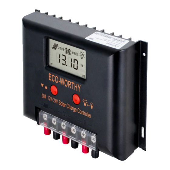
Page 4: Panel Structure
Panel Structure State Indicators Day time Night time Solar panel indication Boost charging Floating charging Equalizing charging Battery overvoltage Battery over discharge Load tumed on Load turned off Overload or short-circuit protection - 2 -... -
Page 5: Five Load Working Modes
Five load Working Modes 1 .Pure light control (0): When sunlight disappears and the light intensity drops to the starting point (light control off), the controller initiates a 10-minute delay (settable) to confirm the starting signal, and then switches on the load for operation. When sunlight emerges and the light intensity reaches the starting point, the controller initiates a 1-minute (fixed) delay to confirm the shutting-down signal, and then shuts down the output to stop the load’s operation. -
Page 6: Load Working Mode Settings
Load Working Mode Settings In the load mode menu, long press for 2s, and the number (e.g. 15) will begin to flash. Press to adjust the mode (from 0 to 17), and then long press again for 2s to complete and save the setting. Note: 1. -
Page 7: Lcd Screen Illustration
LCD Screen Illustration Battery Discharging indicator Solar panel Day time current Charging current Load indicator indicator indicator Night time indicator indicator indicator Charging Units state System Battery type voltage Data Mode Fault indication settings communication method Browsing Menu on LCD Screen 1).Continuously press , the screen will display the following in order: “main menu”---”solar panel voltage1’---”... -
Page 8: Setting Menu On Lcd Screen
Setting Menu on LCD Screen 2). When “load mode” is displayed, long press to enter into the load mode setting. Press to adjust the mode, and long press for 2s to save and exit; or else, the system will not save the setting that was just made and automatically exits the setting after 12s. -
Page 9: Installation Instructions And Precautions
20 s; 5th time, 4 hours or automatic recovery the next day; or long press to make the load resume output. Installation Instructions and Precautions 1) The controller shall be installed securely, and its dimensions are as follows: ECO-SC60A External dimensions: 1893x128x53.1(mm) Installation dimensions: 180x92.2 (mm) - 7 -... - Page 10 Precautions ①If it is 12V system, the bottom left corner of LCD display will show ‘12V’, 24V system will show’ 24V’,36V system will show ‘36V’, 48v system will show ‘48V’. ② The first step is to connect the battery. If the connection is made correctly, the controller screen will light up;...
-
Page 11: Error Code List
Error Code List Common Problems and Solutions - 9 -... -
Page 12: Details Parameter
Details Parameter - 10 -...
Need help?
Do you have a question about the ECO-SC60A and is the answer not in the manual?
Questions and answers