
Related Manuals for ECO-WORTHY GA1012P


Summary of Contents for ECO-WORTHY GA1012P
- Page 1 3000W Hybrid Inverter User Manual +44 20 7570 0328(EU) Tel: E-mail:customer.service@eco-worthy.com Web:www.eco-worthy.com 1-866-939-8222(US)
-
Page 2: Table Of Contents
Contents .............1 Safety Instructions ............2 Introduction ..............2 Features ............3 Product Overview ..............5 Installation ..........5 Unpacking And Inspection .............5 Preparation .............5 Mounting The Unit ...........6 Battery Connection ..........8 Ac Input/Output Connection ............10 PV Connection ............11 Final Assembly .............12 Operation ............12 Power On/Off ........12 Operation And Display Panel ..........16... -
Page 3: Safety Instructions
Safety Instructions WARNING: This chapter contains important safety and operating instructions. Read and keep this manual for future reference. 1.Before using the unit read all instructions and cautionary markings on the unit, the batteries and all appropriate sections of this manual. 2.Do not disassemble the unit Take it to a qualified service center when service or repair is required. -
Page 4: Introduction
Introduction This is a multi-function Inverter/charger, combining functions of inverter, solar charger and battery charger to offer uninterruptible power support with portable size. Its comprehensive LCD display offers user-configurable and easy-acces- sible button operation such as battery charging current, AC/solar charger priori- ty, and acceptable input voltage based on different applications. -
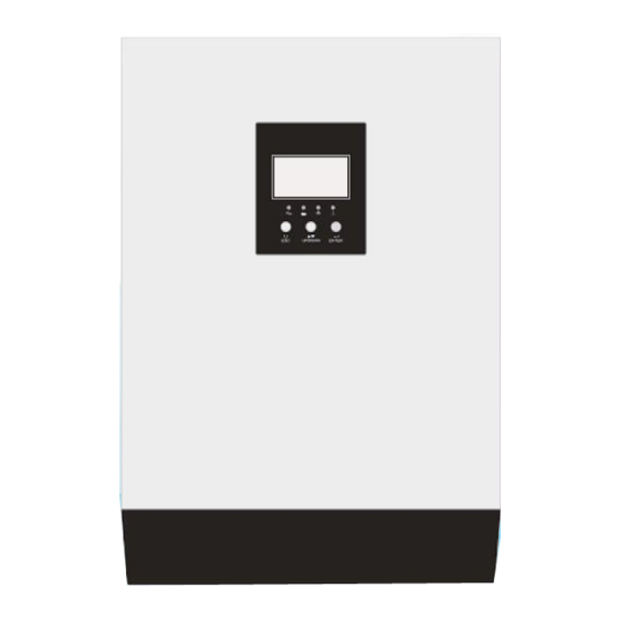
Page 5: Product Overview
Product Overview 1.LCD display 6.Power on/ off switch 11.Circuit breaker 2.Status indicator 7.AC input 12.USB communication port 3.Enter 8.AC output 13.RS-232 communication port 4.Up/Down 9.PV input 5.Esc 10.Battery input... -
Page 6: Installation
Installation Unpacking and Inspection Before installation, please inspect the unit. Be sure that nothing inside the pack- age is damaged. You should have received the following items inside of pack- age: Preparation Before connecting all please take off bottom cover by removing two screws as shown below. -
Page 7: Battery Connection
The ambient temperature should be between and to ensure optimal operation. The recommended installation position is to adhere to the wall vertically. Be sure to keep other objects and surfaces as shown in the diagram to guarantee sufficient heat dissipation and to have enough space for removing wires. - Page 8 Please follow below steps to implement battery connection: Insert the battery wires flatly into battery connectors of inverter and make sure the bolts are tightened. Make sure polarity at both the battery and the inverter/charge is correctly connected and conductors are tightly screwed into the battery terminals.
-
Page 9: Ac Input/Output Connection
WARNING: Shock Hazard Installation must be performed with care due to high battery voltage in series. CAUTION! Be sure in the final connection, positive( + ) must be connected to positive( + ) and negative( -) must be connected to negative (-) AC Input Output Connection CAUTION Before connecting to AC input power source, please Install a separate breaker... - Page 10 Please follow below steps to implement AC input/ output connection 1.Before making AC input/output connection be sure to open DC protector or disconnector first. 2.Remove insulation sleeve 10mm for six conductors. And shorten phase L and neutral conductor N3 mm. 3.Insert AC input wires according to polarities indicated on terminal block and tighten the terminal screws.
-
Page 11: Pv Connection
PV Connection CAUTION: Before connecting to modules, please install separately a DC circuit breaker between inverter and PV modules. WARNING! It's very important for system safety and efficient operation to use appropriate cable for PV module connection. To reduce risk of injury, please use the proper recommended cable size as below. -
Page 12: Final Assembly
PV Module Wire Connection 1.Remove insulation sleeve 10 mm for positive and nega- tive conductors. 2.Fix wire cover to the inverter with supplied screws as below: 3. Check the correct polarity of wire from PV modules and PV input connectors. Connect positive pole( + ) of connection wire to positive pole( + ) of PV input connector. -
Page 13: Operation
Operation Power ON/OFF Once the unit has been properly installed and the batteries are connected well, simply press On/Off switch (located on the button of the case)to turn on the unit. Operation And Display Panel The operation and display , shown in below chart, is on the front panel of the inverter. - Page 14 Buttons Button Instruction Function setting: Press ENTER for more than 2 seconds on the display page to enter ENTER the setting page. And then press the ENTER button to turn and select the different setting pages. UP/DOWN Page turning: Press UP/D0WN button on any page to switch the pages. After setting a single option, press ESC button and then press UP/D0WN to select other option settings.
- Page 15 Parameter query There are total ten pages. Press UP/DOWN button to turn the page. Pages information includes: the input and output voltage, input and output frequency, battery, PV voltage and current, load info, software version, etc. If warning occurs, an warning information page will be added. If the inverter fails, the fault code will be displayed on the page.
- Page 16 Display page 4: output information, output voltage and output active power Display page 5: output information, output voltage and output complex power Display page 6: output information, output voltage and load percentage Display page 7: inverter system software version Display page 8: MPPT system software version -15-...
-
Page 17: Function Setting Operation
Function setting operation Function setting operation: • Press ENTER for more than 2 seconds to enter the function setting page. Press ENTER to select the function. After turning the page to the desired func- tion setting page, the corresponding function words will flash. •... - Page 18 Output frequency (OPF) Set the inverter output frequency. Default is 50Hz 50Hz and 60Hz can be set Setting conditions: All states can be set, and the settings will take effect when the unit restarted next time. Output priority (OPP) Set the inverter priority, the default is GRD: mains output priority The second is PU(PV): PV output priority The third is PBG: photovoltaic cell mains output Setting conditions: All states can be set.
- Page 19 Output mode (MOD) Set the inverter output mode, the default is APP: Appliance, for home applianc- The second is inverter, which is used for equipment such as computers. Setting conditions: All states can be set. Charging priority (CHG) Set the inverter charging priority, the default is PNG (PV and Grid): PV and Grid are charing at the same time The second is OPV (Only PV): only photovoltaic charging The third is GRD (Grid): mains charging priority...
- Page 20 Mains charging current (RCC) Set the maximum value of the inverter's mains charging current. The default mains charging current is 40A Range [1-60A] Setting conditions: All states can be set. Maximum charge current (MCC) Set the maximum charging current value of the inverter. The maximum charging current refers to the maximum value of PV and mains charging current.
- Page 21 Overload restart (LrS) Overload restart is OFF by default. Setting conditions: All states can be set. Over-temperature restart (TrS) Over-temperature restart is OFF by default. Setting conditions: All states can be set. Main input power failure alarm (MIP) Long buzzer setting for mains or PV loss, the default setting is ON, after the main input detection is lost, the buzzer will keep buzzing for 3s When set to OFF, the buzzer will not acitve long after the main input is lost Setting conditions: All states can be set...
- Page 22 Overload to bypass (0LG) When the unit is overloaded in battery mode , set whether to switch to the mains mode immediately, the default setting is OFF, the function is not active When set to ON, under the condition of PV priority output with load, if overload, the system will switch to bypass immediately Setting conditions: All states can be set.
- Page 23 Switch back to battery mode voltage point (BTB) After the battery is turned off at low voltage, it needs to reach a certain battery voltage value before it can be restarted in battery mode. Default setting is 26V Range [24-29] When the output priority is set to photovoltaic (PV) priority output or photovolta- ic battery mains (PBG) output, if it is not in battery mode at this time, if the battery voltage is higher than 27V, the system will switch back to battery mode.
- Page 24 Battery shutdown point (bAU) The battery low voltage shutdown point setting function requires the battery type to be set to CUS (customer set type) to modify the battery shutdown point. Default setting is 21V Range [20-22] Setting conditions: All states can be se Voltage point in constant voltage mode (bCV) The battery type needs to be set to CUS (customer set type) to modify the battery shutdown point.
- Page 25 Mains low voltage point (LLV) Set the mains low voltage protection point, in inverter mode (output mode: MOD needs to be set to APP), the default setting is 154V Range [90-154V] Setting conditions: The inverter is in APP mode, and all states can be set. Mains high voltage point(LHV) Set the mains high voltage protection point, in inverter mode (output mode: MOD needs to be set to APP), the default setting is 264V...
- Page 26 In battery mode, after the continuous discharge time exceeds 8 hours, and the battery shutdown point has not been reached, the battery voltage shutdown point will be modified to 11V * number of battery cells, and the system will alarm for 1 minute when the battery continues to discharge to 11V * number of battery cells then shutdown.
-
Page 27: Battery Equalization Description
Battery Equalization Description Equalization function is added into charge controller, It reverses the buildup of negative chemical effects like stratification, a condition where acid concentra- tion is greater at the bottom of the battery than at the top. Equalization also helps to remove sulfate crystals that might have built up on the plates. - Page 28 Equalize charging time and timeout In Equalize stage, the controller will supply power to charge battery as much as possible until battery voltage raises to battery equalization voltage.Then,con- stant-voltage regulation is applied to maintain battery voltage at the battery equalization voltage. The battery will remain in the Equalize stage until setting battery equalized time is arrived.
-
Page 29: Fault And Alarm Description
Fault and alarm description Fault code Fault icon Alarm icon The alarm code ALA flashes, the buzzer beeps once per second, and lasts for 1 minute. The fault indicator code is always on, the buzzer stops after 10S long beeping, the fault is eliminated after the stop, try to restart the machine, if it fails to restart three times, it will continue in the fault state. - Page 30 The busbar is still lower than 100V after 4s DC Bus soft fauIt fault mode on unrecoverable fault soft start During normal operation, the busbar is instantly Bus short fault fault mode on unrecoverable fault lower than 200V After 40s of inverter soft start, the rated output INV soft fault fault mode on unrecoverable...
-
Page 31: Troubleshooting
Fan lock No fan speed signal Alarm Recoverable No fan speed signal detected detected EEPROM read and EEPROM faiI Alarm unrecoverable EEPROM read and write failed write failed Overload warni ng Alarm Recoverable (load<97%) load>102% load>102% Troubleshooting Problem LCD/LED/Buzzer Possible cause What to do LCD/LEDs and buzzer will Unit shutdown automatical-... -
Page 32: Technical Datasheet
Technical Datasheet Model GA1012P GA2024P GA3024M GA5024M Input format L+N+PE Rated input 208/220/230/240VAC voltage Input Voltage rang 154-264VAC±3V(normal mode)185-264VAC±3V (UPS mode) Frequency range 50Hz/60Hz(adaptive) Rated output 1000W 2000W 3000W 5000W power Rated output 208/220/230/240VAC±5% voltage Frequency 50/60Hz±0.1% Waveform Pure Sine Wave... - Page 33 Maximum PV 55Vdc 80Vdc 145Vdc 450Vdc input voltage Maximum PV charging current Charging Maximum mains charging current Maximum 100A 100A 120A charging current Display LCD interface operating mode/load/input/output, etc. 5PIN/Pitch2.0mm, baud rate 2400 RS232 Expansion slot 2x5PIN/Pitch2.54mm, lithium battery BMS communication card, Interface communication WIFI card, dry contact card, etc.
Need help?
Do you have a question about the GA1012P and is the answer not in the manual?
Questions and answers