Storz OR1 SCB CONTROL Instructions For Use Manual
Hide thumbs
Also See for OR1 SCB CONTROL:
- Installation instructions manual (52 pages) ,
- Instructions for use manual (56 pages)
Table of Contents
Advertisement
Quick Links
Advertisement
Table of Contents

Subscribe to Our Youtube Channel
Related Manuals for Storz OR1 SCB CONTROL


Summary of Contents for Storz OR1 SCB CONTROL
- Page 1 Instructions for use OR1 SCB CONTROL Rel. 3.0...
- Page 2 09-2022 Copyright © All product illustrations, product descriptions, and texts are the intellectual property of KARL STORZ SE & Co. KG. Their use and reproduction by third parties require the express approval of KARL STORZ SE & Co. KG. All rights reserved.
-
Page 3: Table Of Contents
6.3 Equipment list ..........................20 6.4 Checking the functioning of the user interface ................21 6.5 Widgets (compact menus) ......................21 6.5.1 Hiding and displaying widgets ..................23 6.5.2 Setting the set value ..................... 23 Instructions for use • OR1 SCB CONTROL • SBC231_EN_V3.0_09-2022_IFU_CE-MDR... - Page 4 11.6 Table 4 – Emission class and group ..................54 11.7 Table 5 – Recommended separation distances between portable and mobile HF communications equipment and the product ................55 12 Subsidiaries ............................56 Instructions for use • OR1 SCB CONTROL • SBC231_EN_V3.0_09-2022_IFU_CE-MDR...
-
Page 5: General Information
Action to be carried out by several steps: ü Prerequisite that must be met before carrying out an action. Step 1 ð Interim result of an action Step 2 ð Result of a completed action Instructions for use • OR1 SCB CONTROL • SBC231_EN_V3.0_09-2022_IFU_CE-MDR... -
Page 6: Description Of Warning Messages
Designates a possible imminent risk. If this is not avoided, it could lead to minor injuries. NOTICE NOTICE Designates a possibly harmful situation. If this is not avoided, the products could be damaged. Instructions for use • OR1 SCB CONTROL • SBC231_EN_V3.0_09-2022_IFU_CE-MDR... -
Page 7: Normal Use
LCD monitors (touch screens) and has no direct contact with the patient. The KARL STORZ SCB hardware is used to provide a computer system in order to enable use of the KARL STORZ SCB software. The KARL STORZ SCB hardware does not come into direct contact with the patient. -
Page 8: Safety And Warning
Only combine the product with devices and components that are approved for combined use by the manufacturer. Observe the instruction manuals and interface specifications of the devices and components used in combination. Instructions for use • OR1 SCB CONTROL • SBC231_EN_V3.0_09-2022_IFU_CE-MDR... -
Page 9: Risks From Electric Current
Have the device installed and put into service by authorized and trained electricians of KARL STORZ SE & Co. KG or by companies authorized by KARL STORZ. Use either the power cord supplied by KARL STORZ or a power cord which has the same properties and which bears a national mark of conformity. -
Page 10: Observing Ambient Conditions
In order to avoid exposing patients, users, or third parties to harmful electromagnetic interference, the product must not be operated outside of its intended EMC environment. Furthermore, the product must not be operated if the housing, cable, or electromagnetic shielding equipment is damaged. Instructions for use • OR1 SCB CONTROL • SBC231_EN_V3.0_09-2022_IFU_CE-MDR... -
Page 11: Product Description
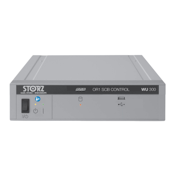
Possibility of later extensions 4.2 Device overview SCB - front panel ON/OFF rocker switch LED, red, hard disk access Standby and operating state LED, yellow, Standby USB port LED, green, ON status Instructions for use • OR1 SCB CONTROL • SBC231_EN_V3.0_09-2022_IFU_CE-MDR... -
Page 12: Possible Combinations
KARL STORZ Touch Screen 21.5" WM100 KARL STORZ Touch Screen 24" WM101 KARL STORZ Touch Screen 21.5" 20090621 KARL STORZ Touch Screen 24" 20090624 OR1 Panel PC 21.5'', InWall W22168-W OR1 Panel PC 21.5'', Stand-Alone W22168-S Instructions for use • OR1 SCB CONTROL • SBC231_EN_V3.0_09-2022_IFU_CE-MDR... -
Page 13: Technical Data
6 kg Device Hard disk capacity 2 TB 16 GB ® Intel Core™ i7-6700@3.4 GHz Operating system Windows 10 IoT The SCB contains a lithium battery that needs to be checked and replaced regularly. Instructions for use • OR1 SCB CONTROL • SBC231_EN_V3.0_09-2022_IFU_CE-MDR... -
Page 14: Symbols Employed
Number of products in the product packaging Unique Device Identifier Consult the printed or electronic instructions for use Fragile, handle with care Keep dry Temperature limit Humidity limit Air pressure limit Instructions for use • OR1 SCB CONTROL • SBC231_EN_V3.0_09-2022_IFU_CE-MDR... -
Page 15: Symbols On The Device
The potential equalization is responsible for equalizing the potentials of differ- ent metal parts that can be touched at the same time, or for reducing potential differences that could occur between the body, electromedical devices, and external live parts during use. Instructions for use • OR1 SCB CONTROL • SBC231_EN_V3.0_09-2022_IFU_CE-MDR... -
Page 16: Symbols On The Type Plate
4.6 Ambient conditions Storage and Transport Conditions Temperature -10 °C ... +60 °C (14 °F ... 140 °F) Relative humidity 5 – 95 % Air pressure 500 – 1,080 hPa Operating conditions Temperature 10 °C ... 40 °C (50 °F ... 104 °F) Relative humidity 20 – 80 % Air pressure 700 – 1,080 hPa Max. operating altitude 3,000 m Instructions for use • OR1 SCB CONTROL • SBC231_EN_V3.0_09-2022_IFU_CE-MDR... -
Page 17: Preparation
Keep air inlets and outlets free. The product can be operated free-standing or in a rack. Ensure that the ambient conditions are observed. Observe the technical data. Install the product out of reach of patients. Instructions for use • OR1 SCB CONTROL • SBC231_EN_V3.0_09-2022_IFU_CE-MDR... -
Page 18: Operation
The information and warnings for the connected device are shown in the header. The messages are displayed as long as the situations prevail. More information, See section Messages [p. 25]. Menu bar The following functions are available in the menu bar: Instructions for use • OR1 SCB CONTROL • SBC231_EN_V3.0_09-2022_IFU_CE-MDR... -
Page 19: Icons On The User Interface
Depending on the configuration, other OR1 components can be accessed via the navigation, such as KARL STORZ AIDA, OR1 FUSION or AV system NEO. The widgets (compact menus) can be displayed and hidden using the Overview button on the right-hand side of the navigation bar. -
Page 20: Equipment List
The device is in Standby mode. Pumps and insufflators: The pumps are switched off. Light sources: The emission of light is interrupted. Out of operation The device is not ready for use. Instructions for use • OR1 SCB CONTROL • SBC231_EN_V3.0_09-2022_IFU_CE-MDR... -
Page 21: Checking The Functioning Of The User Interface
6.5 Widgets (compact menus) Widgets (compact menus) provide the functions of connected devices in a compressed view and are arranged according to categories. Insufflators HF devices Camera systems Motor-operated systems Pumps Light sources Instructions for use • OR1 SCB CONTROL • SBC231_EN_V3.0_09-2022_IFU_CE-MDR... - Page 22 Serial port (1) and set Mode (2) of the connected instrument for AUTOCON and BOWA ARC. Used connection with mode (3) for COVIDIEN – ForceTriad. With motor systems: Display of rotation of direction Instructions for use • OR1 SCB CONTROL • SBC231_EN_V3.0_09-2022_IFU_CE-MDR...
-
Page 23: Hiding And Displaying Widgets
Press on the Overview button again to hide the widgets. 6.5.2 Setting the set value In operating mode the widgets show the actual value of the respective device function. Pumps widget The set value can be set as follows: Instructions for use • OR1 SCB CONTROL • SBC231_EN_V3.0_09-2022_IFU_CE-MDR... -
Page 24: Opening Presets
Application and system administrators can save defined settings for devices in presets. When a preset is selected, the device settings are updated with the values from the preset. Tap Presets in the menu bar. Instructions for use • OR1 SCB CONTROL • SBC231_EN_V3.0_09-2022_IFU_CE-MDR... -
Page 25: Messages
Observe the instructions for use for the equipment to remedy information messages and warnings. 6.7.1 Information Information messages are shown in white font in the header. The information messages are hidden once the cause thereof has been remedied. Instructions for use • OR1 SCB CONTROL • SBC231_EN_V3.0_09-2022_IFU_CE-MDR... -
Page 26: Warnings
High (red, flashing quickly): The problem requires immediate attention as it can affect the safety of the patient or user. – Medium (yellow, flashing slowly): The problem must be remedied at the next opportunity. Instructions for use • OR1 SCB CONTROL • SBC231_EN_V3.0_09-2022_IFU_CE-MDR... - Page 27 Operation – Low (turquoise, not flashing): The problem must be remedied after the operation. The priorities are also shown in the device list with a frame in the corresponding color. Instructions for use • OR1 SCB CONTROL • SBC231_EN_V3.0_09-2022_IFU_CE-MDR...
-
Page 28: Setting Equipment To Standby
ð The software is shut down and the product switches to standby mode. Switch off all connected devices. If the Exit button is pressed for two seconds or longer, the user is logged off but the product does not shut down. Instructions for use • OR1 SCB CONTROL • SBC231_EN_V3.0_09-2022_IFU_CE-MDR... -
Page 29: Equipment
UROMAT E. A. S. I. UP410 Motor systems Unidrive S III UNIDRIVE S III 20701020-1 Unidr. S III ARTHRO UNIDRIVE S III ARTHRO 28723020-1 Unidr. S III ENT UNIDRIVE S III ENT 40701620-1 Unidr. S III NEURO UNIDRIVE S III NEURO 40701720-1 Instructions for use • OR1 SCB CONTROL • SBC231_EN_V3.0_09-2022_IFU_CE-MDR... -
Page 30: Equipment Views
Device functions can be set with the help of widgets, see See section Widgets (compact menus) [p. 21]. No widgets are available for smoke extraction systems, operating lights and operating ta- bles. Instructions for use • OR1 SCB CONTROL • SBC231_EN_V3.0_09-2022_IFU_CE-MDR... -
Page 31: Camera Systems
Refer to the instructions for use of the respective camera system to find out which values can be set. IMAGE 1 HUB IMAGE1 H3-M IMAGE 1 S IMAGE 1 S CONNECT II Instructions for use • OR1 SCB CONTROL • SBC231_EN_V3.0_09-2022_IFU_CE-MDR... -
Page 32: Light Sources
Equipment 7.2.2 Light sources mbi LED Power LED RUBINA Power LED 300 Power LED 175 Instructions for use • OR1 SCB CONTROL • SBC231_EN_V3.0_09-2022_IFU_CE-MDR... -
Page 33: Insufflators
Equipment XENON 300 D-LIGHT P 7.2.3 Insufflators ENDOFLATOR 40, ENDOFLATOR 50 Instructions for use • OR1 SCB CONTROL • SBC231_EN_V3.0_09-2022_IFU_CE-MDR... -
Page 34: Pumps
SCB. Various settings appear in the widgets depending on the set procedure or mode. ARTHROPUMP POWER Instructions for use • OR1 SCB CONTROL • SBC231_EN_V3.0_09-2022_IFU_CE-MDR... - Page 35 Equipment ENDOMAT LC ENDOMAT Select HAMOU Endomat Instructions for use • OR1 SCB CONTROL • SBC231_EN_V3.0_09-2022_IFU_CE-MDR...
-
Page 36: Motor Systems
Equipment HYSTEROMAT E.A.S.I. UROMAT E.A.S.I. 7.2.5 Motor systems UNIDRIVES III Instructions for use • OR1 SCB CONTROL • SBC231_EN_V3.0_09-2022_IFU_CE-MDR... - Page 37 UNIDRIVE S III ARTHRO 7.2.5.1 Non-supported functions SCB does not support all the functions of the motor systems. If a non-supported function is selected, a message appears on the user interface, e.g.: Instructions for use • OR1 SCB CONTROL • SBC231_EN_V3.0_09-2022_IFU_CE-MDR...
-
Page 38: Hf Equipment
7.2.6.1 Widgets The HF devices AUTOCON®, BOWA ARC and COVIDIEN ForceTriad have, in addition to the widgets for setting the set values, the following widgets: – Info widget – Pop-up widget Instructions for use • OR1 SCB CONTROL • SBC231_EN_V3.0_09-2022_IFU_CE-MDR... - Page 39 The Info widget appears if no instrument is acti- vated or if an instrument is connected to or re- moved from the HF device. The Pop-up widget appears, for example, if an alarm is active. Instructions for use • OR1 SCB CONTROL • SBC231_EN_V3.0_09-2022_IFU_CE-MDR...
- Page 40 Equipment 7.2.6.2 AUTOCON III 300 and AUTOCON III 400 AUTOCON III 300 AUTOCON III 400 7.2.6.3 BOWA ARC 400 Instructions for use • OR1 SCB CONTROL • SBC231_EN_V3.0_09-2022_IFU_CE-MDR...
- Page 41 Equipment 7.2.6.4 Valleylab Force FX 7.2.6.5 COVIDIEN ForceTriad The KARL STORZ SCB software version 1.1 and higher supports COVIDIEN ForceTriad version 3.80. The manufacturer must be contacted if another version is operated. Dialog boxes and functions which are not supported SCB does not support the following functions of the COVIDIEN ForceTriad energy platform: –...
-
Page 42: Smoke Extraction Systems
7.2.6.6 Erbe VIO 3 7.2.7 Smoke extraction systems The S-PILOT cannot be switched to the standby mode in the Presets menu. In the device list the Standby button signals that smoke extraction is deactivated. Instructions for use • OR1 SCB CONTROL • SBC231_EN_V3.0_09-2022_IFU_CE-MDR... -
Page 43: Operating Lights And Or Camera Systems
With other operating lights, the button must be pressed for longer (approx. 2 seconds). The information can be found in the instructions for use of the operating lights. Instructions for use • OR1 SCB CONTROL • SBC231_EN_V3.0_09-2022_IFU_CE-MDR... - Page 44 The control panels on the illumination units have a higher priority status than the KARL STORZ SCB software. To prevent the lights being turned on or off accidentally, the On/Off button must be pressed for an extended period. Instructions for use • OR1 SCB CONTROL • SBC231_EN_V3.0_09-2022_IFU_CE-MDR...
-
Page 45: Operating Tables
If the operating table is operated outside a field of view, the patient may fall off. Only move the operating table if it and the patient are in the operator's field of view. Instructions for use • OR1 SCB CONTROL • SBC231_EN_V3.0_09-2022_IFU_CE-MDR... - Page 46 (2) or tilt adjustment (4). ð The operating table is shown in orange, see the Figure above. ð The operating table is moved to the desired position. Instructions for use • OR1 SCB CONTROL • SBC231_EN_V3.0_09-2022_IFU_CE-MDR...
-
Page 47: Maintenance, Servicing, Repairs, And Disposal
KARL STORZ service techni- cians 8.2 Repairs to the product Repair work may only be performed by KARL STORZ or by a company authorized by KARL STORZ. Please contact your local KARL STORZ subsidiary or authorized dealer (see the list of subsidiaries). Contaminated devices may not be shipped. To prevent contact infections and airborne infections, products must first be decontaminated. -
Page 48: Accessories And Spare Parts
RJ-45 network cable, length 500 cm 20040076 21.5" KARL STORZ Touchscreen WM100 24" KARL STORZ Touchscreen WM101 21.5" KARL STORZ Touchscreen, 24V 20090621 24" KARL STORZ Touchscreen, 24V 20090624 SCB Connecting Cable, 100 cm 20090170 Instructions for use • OR1 SCB CONTROL • SBC231_EN_V3.0_09-2022_IFU_CE-MDR... -
Page 49: Errors And Messages
10.1 General faults If the monitoring program detects a malfunction, the user interface is inactive. SCB must be restarted. The following message appears on the display: If the problem reoccurs, the administrator or KARL STORZ service must be contacted. 10.2 Troubleshooting Fault... -
Page 50: Electromagnetic Compatibility
WARNING Reduced immunity! Risk of injury! The use of accessories or cables other than those specified in the KARL STORZ instructions for use may result in increased emissions or decreased immunity of the product. The cables listed have been shown to comply with the requirements of IEC 60601-1-2. - Page 51 315° phase angles and 315° phase angles ated with an uninterrupt- Voltage interruption: Voltage interruption: ible power supply or a 100% for 250/300 cy- 100% for 250/300 cy- battery. cles cles Instructions for use • OR1 SCB CONTROL • SBC231_EN_V3.0_09-2022_IFU_CE-MDR...
- Page 52 GSM 800/900, Pulse modula- TETRA 800, tion iDEN 820, 18 Hz CDMA 850, LTE band 5 1720 1700 – 1990 GSM 1800, Pulse modula- CDMA 1900, tion 1845 GSM 1900, 217 Hz DECT, Instructions for use • OR1 SCB CONTROL • SBC231_EN_V3.0_09-2022_IFU_CE-MDR...
- Page 53 [m]. Field strengths from fixed HF transmitters as determined by an electromagnetic site survey should be less than the compliance level in each frequency range d = 1.2 √P 80 MHz to 800 MHz Instructions for use • OR1 SCB CONTROL • SBC231_EN_V3.0_09-2022_IFU_CE-MDR...
- Page 54 Emission of harmonic oscillations Class A those directly connected to the public acc. to IEC 61000-3-2 low voltage power supply network that supplies buildings used for domestic Voltage fluctuations/flicker emissions Complies purposes. acc. to IEC 61000-3-3 Instructions for use • OR1 SCB CONTROL • SBC231_EN_V3.0_09-2022_IFU_CE-MDR...
- Page 55 Note: At 80 MHz and 800 MHz, the separation distance for the higher frequency range applies. Note: These guidelines may not apply in all situations. The propagation of electromagnetic waves is affected by absorptions and reflections of buildings, objects, and people. Instructions for use • OR1 SCB CONTROL • SBC231_EN_V3.0_09-2022_IFU_CE-MDR...
-
Page 56: Subsidiaries
KARL STORZ Industrial** Gedik Is Merkezi B Blok, Kat 5, D 38-39, Bagdat Cad. No: 162, Maltepe Istanbul, Turkey Phone: +90 216 442 9500, Fax: +90 216 442 9030 **Sales for Industrial Endoscopy Instructions for use • OR1 SCB CONTROL • SBC231_EN_V3.0_09-2022_IFU_CE-MDR... - Page 57 KARL STORZ Endoscopy (Shanghai) Ltd., Chengdu Branch Room 803-805, 8F Jin Jiang International Building, No. 1 West Linjiang Road, Wuhou District, 6100414, Chengdu, People’s Republic of China Phone: +86 28 86587977, Fax: +86 28 86587975 E-mail: info@karlstorz.com.cn Instructions for use • OR1 SCB CONTROL • SBC231_EN_V3.0_09-2022_IFU_CE-MDR...
- Page 58 Subsidiaries Instructions for use • OR1 SCB CONTROL • SBC231_EN_V3.0_09-2022_IFU_CE-MDR...
- Page 59 Subsidiaries Instructions for use • OR1 SCB CONTROL • SBC231_EN_V3.0_09-2022_IFU_CE-MDR...
- Page 60 KARL STORZ SE & Co. KG Dr.-Karl-Storz-Straße 34 78532 Tuttlingen Postfach 230 78503 Tuttlingen Germany Phone: +49 7461 708-0 Fax: +49 7461 708-105 E-mail: info@karlstorz.com www.karlstorz.com...
Need help?
Do you have a question about the OR1 SCB CONTROL and is the answer not in the manual?
Questions and answers