
Related Manuals for Storz XENON NOVA 175


Summary of Contents for Storz XENON NOVA 175
- Page 1 XENON NOVA ® MODEL 20 1315 20 Service Manual Technical Description and Service Instructions XENON NOVA ® MODEL 20 1315 20 September 2013-0.05 SM-20-01-V2.0...
- Page 2 © All pictures, photos and product descriptions are the intellectual property of KARL STORZ GmbH & Co. KG Utilization and copies by third parties have to be authorized by KARL STORZ GmbH & Co. KG All rights reserved. 09.13...
-
Page 3: Table Of Contents
XENON NOVA ® MODEL 20 1315 20 Contents Section Title Page General ........................Instruction Manual ....................Physical Design ....................Exploded views of the XENON NOVA 175 ............® 2.1.1 Exploded view of the XENON NOVA 175 (up to serial no. LF0611830) ....®... - Page 4 XENON NOVA ® MODEL 20 1315 20 Section Title Page Technical data ....................... 3-26 Replacement of Individual Assemblies .............. Information about replacements ................Tools required for replacing the individual assemblies ......... Replacement of the power supply Z07558 (as from serial no. LF0611831) ..Replacement of the fan assembly ................
-
Page 5: General
0. General Thank you for your expression of confidence in the KARL STORZ brand name. Like all of our other prod- ucts, this product is the result of years of experience and great care in manufacture. You and your orga- nization have decided in favor of a modern, high-quality piece of equipment from KARL STORZ. - Page 6 Reservation of Rights This documentation is the sole and exclusive property of KARL STORZ and may neither be copied nor passed on to third parties without the express written authorization and approval of KARL STORZ.
-
Page 7: Instruction Manual
XENON NOVA ® MODEL 20 1315 20 Section 1. Instruction Manual Direction Sign: Physical Design 2 Descriptions of Operation and Circuit Diagrams 3 Replacement of Individual Assemblies 4 Testing and Adjustments 5 Maintenance and Safety Checks ... -
Page 9: Physical Design
XENON NOVA ® MODEL 20 1315 20 Section 2. Physical Design Direction Sign: Instruction Manual Descriptions of Operation and Circuit Diagrams 3 Replacement of Individual Assemblies 4 Testing and Adjustments 5 Maintenance and Safety Checks 6 Modifications and Supplements ... - Page 11 XENON NOVA ® MODEL 20 1315 20 Contents 2. Physical Design Section Title Page Physical Design ....................Exploded views of the XENON NOVA 175 ............® 2.1.1 Exploded view of the XENON NOVA 175 (up to serial no. LF0611830) ....®...
-
Page 12: Exploded Views Of The Xenon Nova
XENON NOVA ® MODEL 20 1315 20 2.1 Exploded views of the XENON NOVA ® 2.1.1. Exploded view of the XENON NOVA 175 (up to serial no. LF0611830) ® 09.13 / V2.0... -
Page 13: Spare Parts Of The Xenon Nova
XENON NOVA ® MODEL 20 1315 20 2.1.2. Spare parts of the XENON NOVA 175 (up to serial no. ® LF0611830) Position Item description Order no. Attenuator assembly, without attenuator disc M19288 20131586 Condenser lens 20131581 Fan assembly (with connector and mounting rivets) 20131585 Power fuse 2 x T 3.15 AL / 250 V (220 VAC …... -
Page 14: Exploded View Of The Xenon Nova
XENON NOVA ® MODEL 20 1315 20 2.1.3. Exploded view of the XENON NOVA 175 (as from serial no. LF0611831) ® 09.13 / V2.0... -
Page 15: Spare Parts Of The Xenon Nova
XENON NOVA ® MODEL 20 1315 20 2.1.4. Spare parts of the XENON NOVA 175 (as from serial no. ® LF0611831) Position Item description Order no. Attenuator assembly, without attenuator disc M19288 20131586 Condenser lens 20131581 Fan assembly (with connector and mounting rivets) 20131585 Power fuse 2 x T 3.15 AL / 250 V (220 VAC …... -
Page 17: Descriptions Of Operation And Circuit Diagrams
XENON NOVA ® MODEL 20 1315 20 Section 3. Descriptions of Operation and Circuit Diagrams Direction Sign: Instruction Manual Physical Design Replacement of Individual Assemblies 4 Testing and Adjustments 5 Maintenance and Safety Checks 6 Modifications and Supplements ... -
Page 19: Description Of Operation Of The Xenon Nova 175
XENON NOVA ® MODEL 20 1315 20 Contents 3. Descriptions of Operation and Circuit Diagrams Section Title Page Descriptions of Operation and Circuit Diagrams ..........Description of operation of the XENON NOVA 175 ..........® 3.1.1 General description ....................3.1.2 Basic features ...................... -
Page 20: Lf0611830)
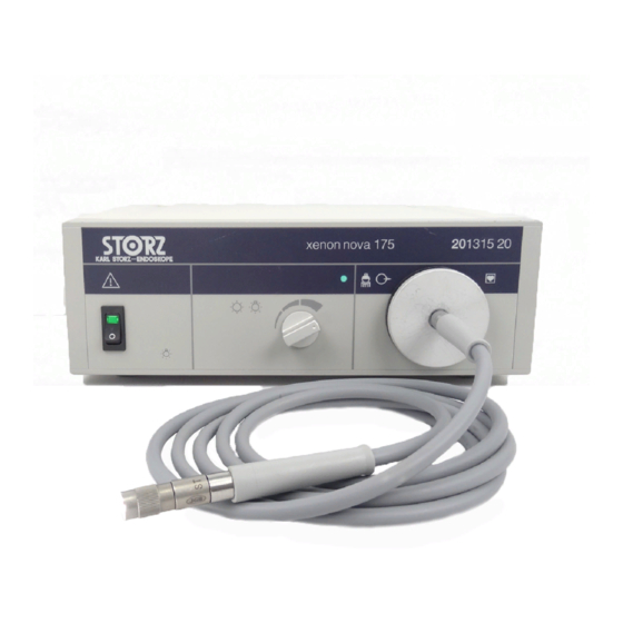
XENON NOVA ® MODEL 20 1315 20 3.1 Description of operation of the XENON NOVA 175 ® 3.1.1. General description The 201315 20 XENON NOVA 175 is a 175 W Xenon light source designed for use in general endo- ® scopic surgery, especially where high light levels may be needed, and where cine, video, or still photo- graphic documentation may be required. -
Page 21: Block Diagram Of The Xenon Nova
XENON NOVA ® MODEL 20 1315 20 3.1.3.2. Block diagram of the XENON NOVA 175 (as from serial no. ® LF0611831) 3.2 Detailed description of operation 3.2.1. Fan The fan is a 12 VDC fan, with power supplied by the power supply. 3.2.2. -
Page 22: Carsan Power Supply (As From Serial No. 0001 Up To 3863)
XENON NOVA ® MODEL 20 1315 20 3.2.3. Carsan power supply (as from serial no. 0001 up to 3863) 3.2.3.1. Description of Carsan power supply operation AC rectifier The power entry module (located on the rear panel) contains two power fuses, one for each side of the AC line. - Page 23 XENON NOVA ® MODEL 20 1315 20 Lamp timer circuit The lamp timer circuit keeps track of lamp usage in hours, and warns the operator that a scheduled lamp change is approaching or overdue. The red LED (D902) on the faceplate will light at approximately 450 hours (90% of the lamp’s expected life) and start blinking at around 500 hours to indicate a lamp change is imperative.
- Page 24 XENON NOVA ® MODEL 20 1315 20 Ignition circuit When the lamp is off, the full B+ voltage through R600 is across the sidac D600 and capacitor C600. When the sidac reaches 95 V, it discharges the capacitor through the L600 inductor (a high-voltage transformer), which through C601, D601, and D602 successively pump charge into capacitors C602 and C603.
- Page 25 XENON NOVA ® MODEL 20 1315 20 3.2.3.2. Circuit diagram of the Carsan power supply (as from serial no. 0001 up to 1050) R102 AC RECTIFIER 1.0M L100 C100 INGNITOR AND LAMP D100 LAMP600 BRIDGE Xenon Lamp 1.0uF S100 J100 Line RV100 T100...
- Page 26 XENON NOVA ® MODEL 20 1315 20 BIAS SUPPLY D404 C412 0.1uF T400 D406 630V R407 B+12 R409 C407 D405 220uF D402 D403 C409 R410 220uF D407 B-12 R408 C405 C406 100uF 47uF C404 D408 +12V 100pF C907 R411 R405 C411 TANT 20.0K...
-
Page 27: Component Diagram Of The Carsan Power Supply (As From Serial No. 0001 Up To 1050)
XENON NOVA ® MODEL 20 1315 20 3.2.3.3. Component diagram of the Carsan power supply (as from serial no. 0001 up to 1050) AC RECTIFIER IGNITOR FET DRIVER LAMP CURRENT CONTROL LOOP BIAS SUPPLY LAMP TIMER CIRCUIT 09.13 / V2.0... - Page 28 XENON NOVA ® MODEL 20 1315 20 3.2.3.4. Circuit diagram of the Carsan power supply (as from serial no. 1051 up to 3863) R102 AC RECTIFIER 1.0M L100 C100 INGNITOR AND LAMP D100 LAMP600 BRIDGE Xenon Lamp 1.0uF S100 J100 Line RV100 T100...
- Page 29 XENON NOVA ® MODEL 20 1315 20 BIAS SUPPLY D404 C412 0.1 F T400 D406 630V R407 B+12 R409 C407 D405 220 F D402 D403 C409 R410 220 F D407 B-12 R408 C405 C406 100 F 47 F C404 D408 +12V 100pF C907...
-
Page 30: Component Diagram Of The Carsan Power Supply (As From Serial No. 1051 Up To 3863)
XENON NOVA ® MODEL 20 1315 20 3.2.3.5. Component diagram of the Carsan power supply (as from serial no. 1051 up to 3863) AC RECTIFIER IGNITOR FET DRIVER LAMP CURRENT CONTROL LOOP BIAS SUPPLY LAMP TIMER CIRCUIT 3-12 3-12 09.13 / V2.0... -
Page 31: Warner Power Supply (As From Serial No. 3864)
XENON NOVA ® MODEL 20 1315 20 3.2.4. Warner power supply (as from serial no. 3864) 3.2.4.1. Description of Warner power supply operation The Warner power supply consists of input filtering, AC rectifier, dual buck regulators, auxiliary 12 V sup- ply, a timing circuit, and a differential lamp igniter. - Page 32 XENON NOVA ® MODEL 20 1315 20 The second stage, powered by the first stage at Vbulk2, is similar. At the control board, the heart of the second stage regulator is U2, a UC3525 pulse-width modulator integrated circuit, the same as the first stage. C12, a 0.01 µF capacitor, and R10, a 2.37 kh resistor, determine the frequency of the second stage.
- Page 33 XENON NOVA ® MODEL 20 1315 20 A red warning indicator lamp, D21, will light when the lamp is about to reach end of life and will start flashing when the lamp has reached the end of life. U5 controls the circuitry, which includes Q6, Q7, Q8, R26, and D21, for this function.
-
Page 34: Circuit Diagram Of The Warner Power Supply (As From Serial No. 3864 Up To Lf0611830)
XENON NOVA ® MODEL 20 1315 20 3.2.4.2. Circuit diagram of the Warner power supply (as from serial no. 3864 up to LF0611830) power supply page 1 of 3 3-16 3-16 09.13 / V2.0... - Page 35 XENON NOVA ® MODEL 20 1315 20 differential ignitor lamp timer circuit power supply page 2 of 3 3-17 09.13 / V2.0...
- Page 36 XENON NOVA ® MODEL 20 1315 20 control board no. 50-334101 power supply page 3 of 3 3-18 3-18 09.13 / V2.0...
-
Page 37: Component Diagram Of The Warner Power Supply
XENON NOVA ® MODEL 20 1315 20 3.2.4.3. Component diagram of the Warner power supply (as from serial no. 3864 up to LF0611830) CONTROL BOARD #50-3341101 3-19 09.13 / V2.0... -
Page 38: Circuit Diagram Of The Warner Power Supply (As From Serial No. Lf0611831)
XENON NOVA ® MODEL 20 1315 20 3.2.4.4. Circuit diagram of the Warner power supply (as from serial no. LF0611831) 3-20 3-20 09.13 / V2.0... -
Page 39: Component Diagram Of The Warner Power Supply
XENON NOVA ® MODEL 20 1315 20 3.2.4.5. Component diagram of the Warner power supply (as from serial no. LF0611831) 3-21 09.13 / V2.0... -
Page 40: Circuit Diagram Of The Timer Pcb (As From Serial No. Lf0611831)
XENON NOVA ® MODEL 20 1315 20 3.2.4.6. Circuit diagram of the timer PCB (as from serial no. LF0611831) Jumper (11-720105) 1-2 FOR TEST in TEST mode the RED led will be on solid after 26min +/-1min. After 29min +/-1min the RED led will start to BLINK on and off. -
Page 41: Light Attenuator
XENON NOVA ® MODEL 20 1315 20 3.2.5. Light attenuator This device attenuates the light output. 3.2.6. 175 W Xenon lamp The lamp always runs at the same power. Turning the brightness control knob does not affect the lamp output; therefore, the lamp lifetime is the same at any brightness level. If the lamp has run for more than 450 h (90% of the lamp’s warranted life of 500 h), the REPLACE LAMP indicator will light while the light source is on. -
Page 42: Component Courses Of Action
XENON NOVA ® MODEL 20 1315 20 General complaint of low brightness – Examine all other parts in the optical system, including the light guide cable, the endoscope, the video camera and lenses. – Measure the power (in W) required by the lamp. Measure the voltage across the R206 resistor and multiply the value by 100. - Page 43 (e.g., the REPLACE LAMP indicator comes on in a few days). • If the replace lamp indicator lights before 450 hours have elapsed, inspect U903. • If U903 is not 54/74HC4017, call KARL STORZ customer service and order a lamp power supply upgrade kit (order no. 201315 80). Install the kit as directed. Visually observe the D903 yellow LED located inside the power supply area next to the battery. With the light source running, the D903 LED should blink at a rate of 2.44 times per second (37 pulses in 15...
-
Page 44: Technical Data
XENON NOVA ® MODEL 20 1315 20 3.4 Technical data XENON NOVA 20 1315 20 ® Supply voltage 100 VAC … 125 VAC / 220 VAC … 240 VAC, w10% Power frequency 50 Hz / 60 Hz Power consumption 400 VA / 350 VA Power fuses 2 x T 3.15 AL / 250 V... -
Page 45: Replacement Of Individual Assemblies
XENON NOVA ® MODEL 20 1315 20 Section 4. Replacement of Individual Assemblies Direction Sign: Instruction Manual Physical Design Descriptions of Operation and Circuit Diagrams Testing and Adjustments 5 Maintenance and Safety Checks 6 Modifications and Supplements 7 Appendix ... - Page 47 XENON NOVA ® MODEL 20 1315 20 Contents 4. Replacement of Individual Assemblies Section Title Page Replacement of Individual Assemblies .............. Information about replacements ................Tools required for replacing the individual assemblies ......... Replacement of the power supply Z07558 (as from serial no. LF0611831) ..Replacement of the fan assembly ................
-
Page 48: Information About Replacements
4.1 Information about replacements The device is fully adjusted and tested before it leaves the manufacturers. If the device fails, a test of the assemblies should be carried out by authorized KARL STORZ technical staff. 4.2 Tools required for replacing the individual assemblies –... -
Page 49: Replacement Of The Power Supply Z07558 (As From Serial No. Lf0611831)
XENON NOVA ® MODEL 20 1315 20 4.3 Replacement of the power supply Z07558 (as from serial no. LF0611831) Refer to Section 4.9 Figures for replacements, Figures 1 and 2. Disconnect the light source from its power source. Remove the outer cover by sliding the interlock slide to the right, removing the four screws on the bottom of the case, and sliding the cover back. -
Page 50: Replacement Of The Attenuator Assembly
XENON NOVA ® MODEL 20 1315 20 4.6 Replacement of the attenuator assembly Refer to Section 4.9 Figures for replacements, Figures 1 and 3. Disconnect the light source from its power source. Remove the outer cover by sliding the interlock slide to the right, removing the four screws on the bottom of the case, and sliding the cover back. -
Page 51: Replacement Of Condenser Lens
XENON NOVA ® MODEL 20 1315 20 4.7 Replacement of condenser lens Refer to Section 4.9 Figures for replacements, Figures 1 and 3. Remove the attenuator assembly as described in Section 4.6 Replacement of the attenuator assembly. Remove the three retaining screws holding the lens. Replace the condenser lens and reassemble in reverse order of disassembly. -
Page 52: Figures For Replacements
XENON NOVA ® MODEL 20 1315 20 4.9 Figures for replacements 4.9.1. Figure 1 (as from serial no. LF0611831) 09.13 / V2.0... - Page 53 XENON NOVA ® MODEL 20 1315 20 4.9.2. Figure 2 (as from serial no. LF0611831) LAMP HEAT SINK, TOP FRONT AND BACK HOT MIRROR ASSEMBLY HEAT SINK, BOTTOM FRONT AND BACK LAMP PCB 09.13 / V2.0...
-
Page 54: Figure
XENON NOVA ® MODEL 20 1315 20 4.9.3. Figure 3 09.13 / V2.0... - Page 55 XENON NOVA ® MODEL 20 1315 20 Section 5. Testing and Adjustments Direction Sign: Instruction Manual Physical Design Descriptions of Operation and Circuit Diagrams Replacement of Individual Assemblies Maintenance and Safety Checks 6 Modifications and Supplements 7 Appendix ...
-
Page 57: Testing And Adjustments
XENON NOVA ® MODEL 20 1315 20 Contents 5. Testing and Adjustments Section Title Page Testing and Adjustments ..................Equipment required for the individual settings ............Test instruments required for the individual adjustment procedures ....Testing and adjusting the lamp current (up to serial no. LF0611830) ....Testing and adjusting the lamp current (as from serial no. -
Page 58: Testing And Adjusting The Lamp Current (As From Serial No. Lf0611831)
Opening the equipment or performance of any repairs or modi- fications of the equipment by unauthorized persons shall relieve KARL STORZ GmbH & Co. KG of any liability for its performance. Any such opening, repair, or modification performed during the warranty period shall void all warranty. -
Page 59: Disabling The Lamp Ignitor
XENON NOVA ® MODEL 20 1315 20 Remove the DVM from the circuit and turn off the power. Reassemble in reverse order of disas- sembly. 5.4 Testing and adjusting the lamp current (as from serial no. LF0611831) Disconnect the power cord from the light source. Remove the outer cover by sliding the interlock slide to the right, removing the four screws on the bottom of the case, and sliding the cover back. -
Page 61: Maintenance And Safety Checks
XENON NOVA ® MODEL 20 1315 20 Section 6. Maintenance and Safety Checks Direction Sign: Instruction Manual Physical Design Descriptions of Operation and Circuit Diagrams Replacement of Individual Assemblies Testing and Adjustments Modifications and Supplements 7 Appendix 8 09.13 / V2.0... - Page 63 XENON NOVA ® MODEL 20 1315 20 Contents 6. Maintenance and Safety Checks Section Title Page Maintenance and Safety Checks ................ Safety checks ......................Safety devices ......................Maintenance operations ..................6.3.1 Lamp replacement ....................6.3.2 Battery replacement ....................6.3.3 Interior cleaning ..................... Servicing and repair ....................
-
Page 64: Safety Checks
– Housing and accessories correct, legible, clean, wipeable, securely attached – Inscriptions, manufacturer’s identification plate data fixed to the housing – CE mark, KARL STORZ inspection label present – Instruction manual correct ratings, undamaged, securely positioned – Power fuses clean, free of grease, securely attached free from visible faults –... -
Page 65: Safety Devices
For lamp replacement instructions, see Section 4.5 Replacement of the lamp. It is recommended that new lamps purchased from a source other than KARL STORZ should be operated for eight hours in the light source prior to clinical use. -
Page 66: Battery Replacement
For telescopes, you receive a guarantee of 1 year, and for instruments 6 months. For fiberscopes and equipment, individual repair is necessary. Usually to bridge the repair period, you will receive a device on loan which you then return to KARL STORZ as soon as you receive the repaired device. - Page 67 XENON NOVA ® MODEL 20 1315 20 6.6 Cleaning and disinfection For detailed information please see instruction manual. 09.13 / V2.0...
-
Page 69: Modifications And Supplements
XENON NOVA ® MODEL 20 1315 20 Section 7. Modifications and Supplements Direction Sign: Instruction Manual Physical Design Descriptions of Operation and Circuit Diagrams Replacement of Individual Assemblies Testing and Adjustments Maintenance and Safety Checks Appendix 8 09.13 / V2.0... - Page 71 XENON NOVA ® MODEL 20 1315 20 Contents 7. Modifications and Supplements Section Title Page Modifications and Supplements ................. Warner power supply information (as from serial no. 3864 up to LF0611830) ..7.1.1 Circuit diagram of the Warner power supply ............7.1.2 Component diagram of the Warner power supply ..........
-
Page 72: Warner Power Supply Information (As From Serial No. 3864 Up To Lf0611830)
XENON NOVA ® MODEL 20 1315 20 7.1 Warner power supply information (as from serial no. 3864 up to LF0611830) The Warner power supply consists of input filtering, AC rectifier, dual buck regulators, auxiliary 12 V sup- ply, a timing circuit, and a differential lamp igniter. Warner power supply input The input power entry starts with two 6.3 A, 250 V fuses (F1 and F2), one on the neutral (“N”) line and the other on the live (“L”) line. - Page 73 XENON NOVA ® MODEL 20 1315 20 The second stage, powered by the first stage at Vbulk2, is similar. At the control board, the heart of the second stage regulator is U2, a UC3525 pulse-width modulator integrated circuit, the same as the first stage. C12, a 0.01 µF capacitor, and R10, a 2.37 kh resistor, determine the frequency of the second stage.
- Page 74 XENON NOVA ® MODEL 20 1315 20 U3 divides the transitions by 16,384 before sending the clock pulses to U4, another MC14020B 14-bit binary counter. For test mode the pulses are approximately 13.1 s apart. In normal operating mode the pulses are approximately 13,386 s (3.7 h) apart.
-
Page 75: Circuit Diagram Of The Warner Power Supply
XENON NOVA ® MODEL 20 1315 20 7.1.1. Circuit diagram of the Warner power supply power supply page 1 of 3 valid for devices as from serial no. 3864 up to LF0611830 09.13 / V2.0... - Page 76 XENON NOVA ® MODEL 20 1315 20 power supply page 2 of 3 valid for devices as from serial no. 3864 up to LF0611830 09.13 / V2.0...
- Page 77 XENON NOVA ® MODEL 20 1315 20 control board no. 50-334101 power supply page 3 of 3 valid for devices as from serial no. 3864 up to LF0611830 09.13 / V2.0...
-
Page 78: Component Diagram Of The Warner Power Supply
XENON NOVA ® MODEL 20 1315 20 7.1.2. Component diagram of the Warner power supply CONTROL BOARD #50-3341101 valid for devices as from serial no. 3864 up to LF0611830 09.13 / V2.0... -
Page 79: Appendix
XENON NOVA ® MODEL 20 1315 20 Section 8. Appendix Direction Sign: Instruction Manual Physical Design Descriptions of Operation and Circuit Diagrams Replacement of Individual Assemblies Testing and Adjustments Maintenance and Safety Checks Modifications and Supplements 09.13 / V2.0... - Page 82 KARL STORZ GmbH & Co. KG Mittelstraße 8, 78532 Tuttlingen/Germany Postfach 230, 78503 Tuttlingen/Germany Phone: +49 (0)7461 708-0 Fax: +49 (0)7461 708-105 E-Mail: info@karlstorz.de Web: www.karlstorz.com KARL STORZ Endoscopy-America, Inc. 2151 East Grand Avenue El Segundo, CA 90245-5017, USA Phone:...
Need help?
Do you have a question about the XENON NOVA 175 and is the answer not in the manual?
Questions and answers