Table of Contents
Advertisement
Available languages
Available languages
Quick Links
Advertisement
Chapters
Table of Contents

Related Manuals for emmeti RECUPERA MED B-140


Summary of Contents for emmeti RECUPERA MED B-140
- Page 1 RECUPERA MED B-140 MANUALE INSTALLAZIONE ED USO INSTALLATION AND USE MANUAL...
-
Page 2: Table Of Contents
Manuale istruzioni (installatore e utente) MED B-140 Unità di ventilazione con recupero di calore Leggere questo manuale attentamente prima di utilizzare il prodotto e conservarlo in un posto sicuro così da poterlo consultare all’occorrenza. Il prodotto è costruito a regola d’arte e nel rispetto delle normative vigenti in materia di apparecchiature elettriche e deve essere installato da personale tecnicamente qualificato. -
Page 3: Avvertenze E Precauzioni
2 AVVERTENZE E PRECAUZIONI ATTENZIONE Assicurarsi che l’interruttore generale dell’impianto sia spento prima di qualsiasi operazione di installazione, manutenzione ordinaria o straordinaria o collegamento elettrico! ATTENZIONE L’installazione e la manutenzione dell’unità e del sistema di ventilazione completo deve essere eseguito da un installatore autorizzato e in conformità... -
Page 4: Dimensioni E Peso
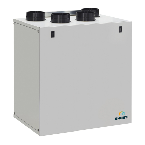
3.2 Dimensioni (mm) e Peso 3.3 Connessioni Fig. 3.a Connessioni Ingresso aria dall’esterno Espulsione aria verso l’esterno Aria fornita all’interno Aria estratta dall’interno Scarico condensa invernale Scarico condensa estivo 3.4 Spazio richiesto Assicurarsi che attorno all’unità vi sia spazio sufficiente per lo svolgimento delle attività di manutenzione (accessibilità ai filtri e alla scatola collegamenti elettrici e rimozione dei pannelli di ispezione laterali e frontali). -
Page 5: Etichetta Dati
3.5 Etichetta dati Fig.3.c Etichetta dati 4 TRASPORTO E IMMAGAZZINAGGIO ATTENZIONE Assicurarsi che le avvertenze e le precauzioni indicate nel Capitolo 2 siano attentamente lette, comprese e rispettate! Il prodotto è fornito in una scatola di cartone. Il prodotto deve essere immagazzinato e trasportato in modo che sia sempre protetto da danni fisici che possono danneggiare le bocche, la carcassa, ecc.. Deve essere coperto in modo che la polvere, la pioggia e la neve non possano entrare e danneggiare l’unità... - Page 6 Distanziali in gomma Fig. 5.d Fig. 5.f Fig. 5.e Livella a Livella a bolla d’aria bolla d’aria Fig. 5.g Ø125mm Ø125mm H=min. 60mm Fig. 5.h Fig. 5.i 5.a Preparare la superficie sulla quale l’unità deve essere montata. Assicurarsi che essa sia piana, livellata e costruita in modo da poter sostenere il peso dell’unità.
-
Page 7: Collegamento Elettrico Precablato
5.4 Collegamento elettrico precablato ATTENZIONE Assicurarsi che l’interruttore generale dell’impianto sia spento prima di qualsiasi operazione di installazione, manutenzione ordinaria o straordinaria o collegamento elettrico! ATTENZIONE L’installazione e la manutenzione dell’unità e del sistema di ventilazione completo deve essere eseguito da un installatore autorizzato e in conformità alle leggi e ai regolamenti vigenti. -
Page 8: Collegamenti Elettrici Alternativi
BYPASS INTERRUTTORE PER SELEZIONE VELOCITÀ 2 Funzionamento a velocità variabile tramite sistema domotico Funzionamento a due velocità esterno (BMS) o potenziometro ballast Assorbimento elettrico RECUPERA MED B-140 Posizione A (20%) B (35%) C (50%) D (60%) E (67%) F (85%) - Page 9 Dip switch Operation Velocità singola Due velocità Funzionamento a velocità variabile tramite sistema domotico esterno (BMS) o potenziometro ballast 3 velocità con SEL42M-SEL4W (Fig. 5k) X : Il Dip 1 è ad uso interno e non va modificato...
-
Page 10: Messa In Servizio
6 MESSA IN SERVIZIO 6.1 Settaggio velocità dei ventilatori La velocità dei ventilatori viene settata in fabbrica come segue: velocità 1 al 40%, velocità 2 al 70% e velocità 3 al 100%. Se necessario la velocità dei ventilatori può essere regolata durante l‘installazione in base al tasso di ventilazione richiesta. La figura 6.a indica la curva di prestazione alle diverse regolazioni del segnale 0-10V fornito ai motori. -
Page 11: Prima Di Avviare Il Sistema
Tabella 6.c Emissioni sonore Lw dB - LIVELLO DI POTENZA SONORA PER BANDA DI OTTAVA Lp dB(A) 100% Lato immissione aria dall’esterno (Intake) Lato immissione aria verso l’interno (Supply) Lato estrazione aria dall’interno (Extract) Lato espulsione aria verso l’esterno (Exhaust) Involucro (Breakout) Lp dB(A) Lw dB - LIVELLO DI POTENZA SONORA PER BANDA DI OTTAVA... -
Page 12: Funzionamento
7 FUNZIONAMENTO ATTENZIONE Assicurarsi che le avvertenze e le precauzioni indicate nel Capitolo 2 siano attentamente lette, comprese e rispettate! 7.1 Funzionamento a 3 velocità con comando SEL42M-SEL4W (accessorio su richiesta) L’unità funziona alla velocità stabilita agendo sui deviatori “S1”, S2” e “S3” del comando SEL42M-SEL4W (accessorio Fig. 5.k) “S1”... -
Page 13: Manutenzione Ordinaria E Straordinaria
8 MANUTENZIONE ORDINARIA E STRAORDINARIA ATTENZIONE Assicurarsi che le avvertenze e le precauzioni indicate nel Capitolo 2 sia attentamente lette, comprese e rispettate! La manutenzione ordinaria può essere eseguita dall’utente. La manutenzione straordinaria deve essere eseguita unicamente da un installatore autorizzato e in conformità alle norme e regolamenti locali in vigore. -
Page 14: Manutenzione Ordinaria
8.3 Manutenzione ordinaria ATTENZIONE Assicurarsi che l’interruttore generale dell’impianto sia spento prima di qualsiasi operazione di installazione, manutenzione ordinaria o straordinaria o collegamento elettrico! • Tenere la superficie dell’unità pulita dalla polvere. • Ogni 3 mesi (periodo fisso) l’unità avvisa l’utente, tramite segnalazione visiva (luce rossa), di effettuare la manutenzione del filtro. La necessità di eseguire questa operazione può... -
Page 15: Manutenzione Straordinaria
8.4 Manutenzione straordinaria ATTENZIONE Assicurarsi che l’interruttore generale dell’impianto sia spento prima di qualsiasi operazione di installazione, manutenzione ordinaria o straordinaria o collegamento elettrico! ATTENZIONE L’installazione e la manutenzione dell’unità e del sistema di ventilazione completo deve essere eseguito da un installatore autorizzato e in conformità... -
Page 16: Risoluzione Guasti
Fig. 8.r Fig. 8.s Fig. 8.t 8.5 Risoluzione guasti I ventilatori non si attivano 1. Verificare che l’unità sia sotto tensione. 2. Verificare che tutti i collegamenti funzionino correttamente (collegamenti nella scatola collegamenti elettrici e al gruppo dei ventilatori in immissione ed estrazione). - Page 17 Dichiara inoltre di aver preso visione della Informativa sui dati personali disponibile anche sul sito internet di Emmeti S.p.A. EMMETI spa - Via brigata Osoppo, 166 - 33074 Vigonovo frazione di Fontanafredda (PN) - Italia - Tel.0434567911 - Fax 0434567901 - www.emmeti.com...
-
Page 19: Index
Installation Manual (installer & user) MED B-140 Heat Recovery Ventilation Unit Read this manual carefully before using the product and keep it in a safe place for reference as necessary. This product was constructed up to standard and in compliance with regulations relating to electrical equipment and must be installed by technically qualified personnel. -
Page 20: Precautions
2 PRECAUTIONS WARNING Make sure that the mains supply to the unit is disconnected before performing any installation, service, maintenance or electrical work! WARNING The installation and service of the unit and complete ventilation system must be performed by an authorized installer and in accordance with local rules and regulations. -
Page 21: Dimensions And Weight
3.2 Dimensions (mm) and Weight 3.3 Connections Fig. 3.a Connections Intake air from outside Exhaust air to outside Supply air to inside Extract air from inside Winter condensation drainage Summer condensation drainage 3.4 Space required Make sure that enough space is left around the unit to allow easy maintenance (access to filters, terminal box and removal of the side and front inspection panels). -
Page 22: Rating Label
3.5 Rating label Fig.3.c Rating label 4 TRANSPORT AND STORAGE WARNING Make sure that specific warnings and cautions in Chapter 2 “Precautions” are carefully read, understood and applied! The appliance is delivered in one carton box. The appliance should be stored and transported in such a way that it is protected against physical damage that can harm spigots, casing etc. It should be covered so that dust, rain and snow cannot enter and damage the unit and its components. - Page 23 Rubber spacers Fig. 5.d Fig. 5.f Fig. 5.e Spirit level Spirit level Fig. 5.g Ø125mm Ø125mm H=min. 60mm Fig. 5.h Fig. 5.i 5.a Prepare the surface where the unit is to be mounted. Make sure that the surface is flat, leveled and that it supports the weight of the unit. Perform the installation in accordance with local rules and regulations.
-
Page 24: Precabled Electric Connections
5.4 Precabled Electric Connections WARNING Make sure that the mains supply to the unit is disconnected before performing any installation, service, maintenance or electrical work! WARNING The installation and service of the unit and complete ventilation system must be performed by an authorized installer and in accordance with local rules and regulations. -
Page 25: Additional Electric Connections
SWITCH FOR BYPASS ACTIVATION SWITCH FOR SPEED 2 SELECTION Variable speed operation through external domotic (BMS) system Two speed operation or ballast potentiometer Power consumption RECUPERA MED B-140 Position A (20%) B (35%) C (50%) D (60%) E (67%) F (85%) - Page 26 Dip switch Operation Single speed Two speed Variable speed throught external domotic (BMS) system or ballast potentiometer Three speed with SEL42M-SEL4W (Fig. 5k) X : Dip 1 switch is for factory setting only and it does not have to be changed.
-
Page 27: Commissioning
6 COMMISSIONING 6.1 Setting Fan speed Speed factory settings: speed 1 at 40%, speed 2 at 70% and speed 3 set at 100%. The speed of the unit can be adjusted during installation according to required ventilation rate. Figure 6.a below shows performance curve at different settings of the 0-10V signal to the motors. Consumption refer to the 2 motors. Table 6.b indicates the efficiency of the heat exchanger and of the condensation produced in different climatic conditions, to help the installer or the designer of the ventilation system to decide if to connect one or both condensation drainages. -
Page 28: Before Starting The System
Table 6.c Sound level Lw dB - SOUND POWER OCTAVE BAND Lp dB(A) 100% Intake Supply Extract Exhaust Breakout Lw dB - SOUND POWER OCTAVE BAND Lp dB(A) Intake Supply Extract Exhaust Breakout Lw dB - SOUND POWER OCTAVE BAND Lp dB(A) Intake Supply... -
Page 29: Operation
7 OPERATION WARNING Make sure that specific warnings and cautions in Chapter 2 “Precautions” are carefully read, understood and applied! 7.1 Three speed operation with SEL42M-SEL4W controller (accessory on request) The unit runs at the speed selected by activating the two-position switches “S1”, “S2” and “S3” of the SEL42M-SEL4W (accessory Fig. 5.k). “S1”... -
Page 30: Maintenance And Service
8 MAINTENANCE AND SERVICE WARNING Make sure that specific warnings and cautions in Chapter 2 “Precautions” are carefully read, understood and applied! Maintenance can be carried out by the user. Service must be performed only by an authorized installer and in accordance with local rules and regulations. Questions regarding installation, use, maintenance and service of the unit should be answered by your installer or place of purchase! 8.1 Components list G4 FILTER... -
Page 31: Maintenance
8.3 Maintenance WARNING Make sure that the mains supply to the unit is disconnected before performing any installation, service, maintenance or electrical work! • Keep the unit surface free from dust. • Once every 3 months (fixed period), the unit warns the user to perform the filter maintenance (red light). The actual need to perform this operation may vary depending on indoor and outdoor ambient conditions. -
Page 32: Service
8.4 Service WARNING Make sure that the mains supply to the unit is disconnected before performing any installation, service, maintenance or electrical work! WARNING The installation and service of the unit and complete ventilation system must be performed by an authorized installer and in accordance with local rules and regulations. -
Page 33: Trouble Shooting
Fig. 8.r Fig. 8.s Fig. 8.t 8.5 Trouble shooting Fans do not start 1. Check that main supply gets to the unit. 2. Check that all connections are working (all connections in terminal box and fast couplings of intake and exhaust air fans). 3. -
Page 34: Schede Prodotto
For unidirectional units: instructions for natural air supply/extraction; not applicable Indirizzo internet con le istruzioni di preassemblaggio e disassemblaggio; www.emmeti.com Internet address for pre-/dis-assembly instructions; non applicabile Per le unità non da canale: sensibilità del flusso d’aria alle variazioni di pressione a +20 Pa e -20 Pa;... - Page 36 SMALTIMENTO E RICICLAGGIO - Informazione per la tutela Le unità sono conformi alle seguenti direttive europee: 2009/125/EC Eco-Progettazione (ErP) dell’ambiente! EU 1253/2014 Direttiva 2012/19/CE (RAEE): informazioni agli utenti 2010/30/UE Etichettatura Energetica Questo prodotto é conforme alle Direttive UE 2012/19/CE. Il simbolo EU 1254/2014 del cestino barrato riportato sotto l'apparecchio indica che il 2011/65/EC Restrizioni sull’uso di determinate sostanze pericolose (RoHS)
Need help?
Do you have a question about the RECUPERA MED B-140 and is the answer not in the manual?
Questions and answers