
Related Manuals for emmeti Recupera DRY 500


Summary of Contents for emmeti Recupera DRY 500
- Page 1 RECUPERA DRY 500 UNITÀ DI VENTILAZIONE MECCANICA CONTROLLATA CONTROLLED MECHANICAL VENTILATION UNIT MANUALE ISTALLAZIONE ED USO INSTALLATION AND USE MANUAL...
-
Page 2: Table Of Contents
® Tutti i diritti riservati. Nessuna parte di questa pubblicazione può essere ® All rights reserved. No part of this pubblication may be reproduced or riprodotta o distribuita senza il permesso scritto di Emmeti. distributed without written permission from Emmeti. -
Page 3: Trasporto E Immagazzinamento
IT IT 1. DESCRIZIONE DEI COMPONENTI 1. TRASPORTO E IMMAGAZZINAMENTO CONTENUTO DELLA CONFEZIONE DESCRIZIONE DELLA MACCHINA E COMPONENTI PRINCIPALI L’unità RECUPERA DRY-500 viene imballata su pallet di legno e protetto da L’unità RECUPERA DRY-500 è in grado di effettuare, in abbinamento ad un una scatola di cartone. - Page 4 IT IT 1. TRASPORTO E IMMAGAZZINAMENTO Possono essere effettuati i seguenti trattamenti dell’aria: Le portate d’aria possono assumere i seguenti valori: - rinnovo dell’aria con recupero di calore ad alta efficienza, con eventuale - aria immessa in ambiente, portata impostabile da 250 mc/h fino a 500 riscaldamento invernale o raffrescamento estivo;...
-
Page 5: Dimensioni - Installazione
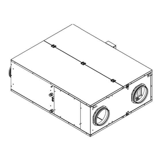
IT IT 2. DIMENSIONI - INSTALLAZIONE 1. DESCRIZIONE DEI COMPONENTI DIMENSIONI 1290 1233 1200 Servomotori serrande... - Page 6 IT IT 2. DIMENSIONI - INSTALLAZIONE INSTALLAZIONE Posizionamento NOTE PER LA SICUREZZA La macchina deve essere installata all’interno di edifici, in posizione oriz- zontale. Il funzionamento in posizione inclinata oltre 1% può comportare L’installazione e la manutenzione vanno eseguiti solo da personale qualifi- perdite d’acqua o danneggiamento dei dispositivi interni.
-
Page 7: Collegamenti
IT IT IT IT 3. COLLEGAMENTI 1. DESCRIZIONE DEI COMPONENTI COLLEGAMENTI Legenda 10 - aspirazione aria viziata; 1 - ingresso acqua fredda/calda; 11 - presa aria di ricircolo; 2 - uscita acqua fredda/calda; 12 - mandata aria agli ambienti; Visibilità LED della 3 - ingesso collegamenti elettrici;... -
Page 8: Collegamenti Aeraulici
IT IT 3. COLLEGAMENTI Nelle tubazioni di scarico vanno previsti tre sifoni oppure l’apposita valvola come riportato di seguito. I sifoni sono necessari per evitare il risucchio di odori; devono essere indipendenti, con una differenza di altezza minima di 40 mm e installati nei pressi dei condotti di scarico della macchina. - Page 9 IT IT 3. COLLEGAMENTI 1. DESCRIZIONE DEI COMPONENTI SCHEDA ELETTRONICA A BORDO MACCHINA Alimentazione elettrica 230 V~ Connessione valvola acqua H2O Valv. MODbus Collegamento a pannello SIGN di controllo COLLEGAMENTO DEL PANNELLO DI CONTROLLO Se la linea seriale di comunicazione tra pannello di controllo e unità RECU- LED Verde PERA DRY-500 è...
-
Page 10: Dati Tecnici
IT IT 4. DATI TECNICI Dati tecnici Generali u.m. DRY-500 Alimentazione elettrica V~ / Hz 230 / 50 Potenza assorbita massima 1080 Corrente massima Grado di protezione IP IP42 Refrigerante (tipo/GWP) R410a/ GWP = 2088 Carica del refrigerante/CO kg / t 0,45/0,94 Pressione di esercizio - Max-Min (AP/BP) 4,1 / 0,5... - Page 11 IT IT 4. DATI TECNICI Funzionamento di trattamento dell'aria u.m. DRY-500 in rinnovo + ricircolo (1) Portata aria nominale (rinnovo + ricircolo) m³/h 500 (210 + 290) Portata acqua nominale totale = l / h batteria di pre-raffreddamento + condensatore Perdita di carico nominale totale = batteria di pre-raffreddamento + condensatore Livello di pressione sonora a 1m...
-
Page 12: Funzionamento
IT IT 5. FUNZIONAMENTO AVVIAMENTO E COLLAUDO Prima di avviare la macchina è necessario realizzare tutti gli allaccia- menti idraulici, aeraulici ed elettrici. Verificare inoltre la disponibilità Alimentazione elettrica 230 V~ dell’acqua refrigerata e l’assenza di perdite di acqua dalle connessio- Connessione valvola acqua ni e dalla macchina. - Page 13 IT IT 1. DESCRIZIONE DEI COMPONENTI 5. FUNZIONAMENTO Le impostazioni disponibili da tastiera sono: - attivazione delle funzioni (in alternativa ai consensi digitali); - ora corrente; - stagione corrente (in alternativa al consenso digitale); - portate d’aria in mandata e in rinnovo; - temperatura di mandata normale e di integrazione per ciascuna stagione;...
- Page 14 IT IT 5. FUNZIONAMENTO MODALITA’ DI FUNZIONAMENTO IN STAGIONE ESTIVA I ventilatori sono entrambi in moto e provvedono al rinnovo: l’aria esterna viene raffreddata prima dal recuperatore, tramite l’aria espulsa, e poi dall’acqua refrigerata della batteria alettata. Il compressore ed il ventilatore di mandata sono in moto;...
- Page 15 IT IT 5. FUNZIONAMENTO 1. DESCRIZIONE DEI COMPONENTI Entrambi i ventilatori sono in moto, la serranda dell’aria esterna immessa è chiusa e al suo posto è aperta la serranda di bypass. L’aria immessa viene trattata dalla batteria ad acqua refrigerata. La portata d’aria è...
- Page 16 IT IT 5. FUNZIONAMENTO I ventilatori sono entrambi in moto. L’aria immessa vie- ne riscaldata dalla batteria ad acqua. L’aria di rinnovo viene preriscaldata, tramite il recuperatore, dall’aria espulsa. La portata d’aria immessa è impostabile da 250 a 500 mc/h, mentre la quota di rinnovo può essere impostata da 160 a 300 mc/h.
-
Page 17: Pannello Di Controllo
IT IT 6. PANNELLO DI CONTROLLO 1. DESCRIZIONE DEI COMPONENTI PANNELLO DI CONTROLLO – INSTALLAZIONE E UTILIZZO Il pannello di controllo remoto va montato su guida DIN in un quadro elettri- co a parete; lo spazio occupato è di 6 moduli. Il pannello di controllo è... -
Page 18: Ingressi Digitali
IT IT 6. PANNELLO DI CONTROLLO FUNZIONI DISPONIBILI PER IL TRATTAMENTO INGRESSI DIGITALI DELL’ARIA - COM: morsetto comune per tutti gli ingressi; - DI01: segnalazione della stagione, 1 = estate, 0 = inverno, se la stagione è - Rinnovo: viene effettuato il rinnovo dell’aria con la portata prevista per il impostata da ingresso digitale invece che da tastiera;... - Page 19 Premere un tasto per accendere IT IT 6. PANNELLO DI CONTROLLO 1. DESCRIZIONE DEI COMPONENTI Stato >spento Schermata dello stato unità Se la macchina è accesa la schermata La schermata iniziale riporta informazioni quali l’ora, la stagione impostata e iniziale è la seguente: l’elenco delle funzionalità...
- Page 20 6. PANNELLO DI CONTROLLO IT IT IMPOSTAZIONE DEGLI ORARI E’ possibile impostare delle fasce orarie per l’attivazione automatica del rinnovo o della attenuazione della portata d’aria; l’attenuazione è utile per ottenere una riduzione del rumore prodotto dal movimento dell’aria. IMPOSTAZIONE DI UNA FASCIA ORARIA Dalla schermata dei menu selezionare “Orari di rinnovo”...
- Page 21 IT IT 6. PANNELLO DI CONTROLLO 1. DESCRIZIONE DEI COMPONENTI Portate: questa voce del menu è il sottomenu delle portate d’aria. Imposta controllo filtri: imposta una procedura per il controllo della pulizia dei filtri dell’aria. Portata Norm: Att: Rinn. Amb. FreeC.
-
Page 22: Diagnostica
IT IT 7. DIAGNOSTICA DIAGNOSTICA Il pannello di controllo visualizza i messaggi di allarme e di guasto comunicati dalla scheda elettronica a bordo macchina. I messaggi sono tutti codifica- ti con un numero multiplo di 2 e sono di due tipi: - messaggi di guasto, indicano un sensore mal funzionante;... - Page 23 IT IT 1. DESCRIZIONE DEI COMPONENTI 7. DIAGNOSTICA SONDE NTC (10 kOhm) E SENSORI : COLORI E POSIZIONE Sensori Portata /Temperatura/ Umidità Aria su Sonde Temperatura su scheda NTC1 scheda elettronica elettronica NTC1 – BIANCO (vedi foto) integrata al sensore presente sulla mandata aria ambiente interno –...
- Page 24 IT IT 1. DESCRIZIONE DEI COMPONENTI 7. DIAGNOSTICA NTC3 – ROSSO (TEMPERATURA COMPRESSORE) NTC4 – BLU (TEMPERATURA SURRISCALDAMENTO) NTC6 – MARRONE (TEMPERATURA SOTTORAFFREDDAMENTO CONDENSATORE A – su uscita EV2) NTC5 – VERDE (TEMPERATURA SOTTORAFFREDDAMENTO NTC7 – GRIGIO CONDENSATORE B – su uscita EV1) (TEMPERATURA ACQUA IN INGRESSO)
- Page 25 IT IT 7. DIAGNOSTICA Sensore (ROSSO) presente su estrazione aria viziata dall’interno: Sensore (GIALLO) presente su aspirazione aria dall’esterno: Questo sensore , che ha 3 pin in più degli altri due sensori, oltre alla portata aria e alla temperatura aria ambiente esterno, misura anche l’umidità dell’aria in ingresso dall’esterno.
-
Page 26: Manutenzione
IT IT 8. MANUTENZIONE ABBINAMENTO MOTORI – SERRANDE : Verde Rosso Bianco Giallo Giallo Bianco Rosso Verde Azionamento manuale servomotore serrande: L'azionamento manuale è possibile con l'ausilio di un magnete (gli ingranaggi restano disinseriti fino a quando il magnete aderisce al simbolo dello stesso). Posizionare il magnete dove indicato dalla freccia nella figura di lato. - Page 27 IT IT 8. MANUTENZIONE 1. DESCRIZIONE DEI COMPONENTI Rimozione filtri MANUTENZIONE La manutenzione periodica consiste nella pulizia dei filtri dell’aria. Per l’asportazione e pulizia dei filtri: - svitare i pomelli che fissano il coperchio dei filtri, vicino al boccaglio di aspirazione;...
-
Page 28: Schema Elettrico
IT IT 9. SCHEMA ELETTRICO FAN 1 room air delivery FAN 2 Expulsion fan... - Page 29 IT IT...
-
Page 30: Demolizione E Smaltimento
9. DEMOLIZIONE E SMALTIMENTO IT IT NOTA INFORMATIVA RAEE Ai sensi dell’art. 26 del Decreto Legislativo 14 marzo 2014, n. IT IT 49 “Attuazione della Direttiva 2012/19/UE sui rifiuti di apparec- chiature elettriche ed elettroniche (RAEE)”. Il simbolo del cassonetto barrato riportato sull’apparecchiatura indica che all’interno dell’Unione Europea tutti i prodotti elettrici ed elettronici alla fine della propria vita utile devono essere raccolti separatamente dagli altri rifiuti. -
Page 31: Garanzia
- Compilare in modo chiaro e leggibile in tutte le sue parti il Certificato di Garanzia. - Spedire a Emmeti S.p.A. in una busta la parte del Certificato di Garanzia entro 10 gg dalla data di installazione/prima accensione. La mancata spedizione del Certificato di Garanzia o l’errata compilazione dello stesso comporta la decadenza della Garanzia. - Page 33 Index 1. Trasport and storage ..... 34 2. Dimension - Installation ....38 3. Connections ......... 38 4. Tecnical Data ........41 5. Operation ........43 6. Control Panel ....... 48 7. Diagnostics ........53 8. Maintenance ........ 57 9. Wiring diagram ......60 10.
-
Page 34: Transport And Storage
1. TRANSPORT AND STORAGE PACKAGE CONTENT NOTE The unit is packed on a wooden pallet and protected by a cardboard box. Manual handling of the machine must be carried out in compliance with The packaging contains: current legislation. - 1 machine RECUPERA DRY-500; - 1 use and maintenance manual. - Page 35 1. TRANSPORT AND STORAGE The following air treatments can be carried out: The air flow rates can assume the following values: - air renewal with high efficiency heat recovery, with possible winter - air introduced into the environment, flow rate settable from 250 mc / h up heating or summer cooling;...
- Page 36 2. TRANSPORT AND STORAGE DIMENSIONS 1290 1233 1200 Damper motors...
-
Page 37: Installation
2. TRANSPORT AND STORAGE INSTALLATION POSITIONING SAFETY WARNINGS The machine must be installed inside buildings, in a horizontal position. Operation in an inclined position over 1% can lead to water leaks or dama- Installation and maintenance must only be performed by qualified person- ge to internal devices. - Page 38 3. CONNECTIONS CONNECTIONS LEGEND 8 - expulsion of stale air; 1 - cold / hot water inlet; 9 - external air intake; Visibility of the modulating 2 - cold / hot water outlet; 10 - stale air intake; water valve LED 3 - electrical connections input;...
-
Page 39: Aeraulic Connections
3. CONNECTIONS Three siphons or the special valve as shown below must be provided in the drain pipes. The siphons are necessary to avoid the suction of odors; must be independent, with a minimum height difference of 40 mm and installed near the ma- chine exhaust ducts. -
Page 40: Led Green
3. CONNECTIONS ELECTRONIC BOARD ON THE MACHINE 230 V~ power supply Water valve connection H2O Valv. MODbus Panel connection SIGN control CONTROL PANEL CONNECTION If the serial communication line between the control panel and the RECUPERA DRY-500 unit is longer than 25 meters, it is necessary to insert a termination resistor of 120 Ohm, ¼... -
Page 41: Technical Data
4. TECHNICAL DATA General u.m. DRY-500 Power supply V~ / Hz 230 / 50 Maximum absorbed power 1080 Maximum current IP protection degree IP42 Refrigerant (type / GWP) R410a/ GWP = 2088 Refrigerant charge / CO kg / t 0,45/0,94 Operating Pressure - Max-Min (AP / BP) 4,1 / 0,5 Net weight... - Page 42 4. TECHNICAL DATA Air treatment operation in renewal + recir- Renewal + Dehumidification u.m. DRY-500 culation (1) Renewal + Cooling Nominal air flow (renewal + recirculation) m³/h 500 (210 + 290) Total nominal water flow = pre-cooling coil + l / h condenser Total nominal pressure drop = pre-cooling coil + Side...
-
Page 43: Operation
5. OPERATION START-UP AND TESTING Before starting the machine it is necessary to make all the hydraulic, aeraulic and electrical connections. Also check the availability of 230 V~ power supply chilled water and the absence of water leaks from the connections and from the machine. - Page 44 5. OPERATION The available keyboard settings are: - activation of functions (as an alternative to digital consents); - current time; - current season (as an alternative to digital consent); - delivery and renewal air flow rates; - normal flow and integration temperature for each season; - automatic renewal time slots (maximum 4);...
- Page 45 5. OPERATION SUMMER SEASON OPERATING MODES METHOD OF OPERATION IN THE SUMMER SEASON ONLY RENEWAL The fans are both in motion and provide for renewal: the external air is cooled first by the recuperator, through the expelled air, and then by the chilled water of the finned coil OUTDOOR INDOOR...
- Page 46 5. OPERATION BYPASS OF THE HEAT RECOVERY UNIT Both fans are running, the external air damper is closed and the bypass damper is open in its place. The injected air is treated by the chilled OUTDOOR INDOOR water coil. The air flow can be set from 160 to 300 cubic meters / h.
- Page 47 5. OPERATION RENEWAL + RECIRCULATION The fans are both running. The injected air is hea- ted by the water coil. The renewal air is preheated, through the recuperator, by the expelled air. The flow of air injected can be set from 250 to 500 cubic meters / h, while the renewal rate can be set from OUTDOOR INDOOR...
-
Page 48: Control Panel
6. CONTROL PANEL CONTROL PANEL - INSTALLATION AND USE The remote control panel must be mounted on a DIN rail in a wall-mounted electrical panel; the space occupied is 6 modules. The control panel is equipped with n. 3 terminal blocks, on which to connect: - the connection to the machine, via the 4 wires that allow the panel power supply (24VDC) and serial communication with the electronic board;... - Page 49 6. CONTROL PANEL AVAILABLE FUNCTIONS FOR AIR TREATMENT but allows to keep the ambient air moving (RECIRCULATION); - DI03 :; renewal consent; - Renewal: the renewal of the air is carried out with the expected flow rate - DI04: dehumidification consent; for the renewal, using the heat recovery unit;...
- Page 50 Press any key to switch ON Status 6. CONTROL PANEL To switch from OFF to ON, press the button >OFF the button ; pressing the button status is confirmed and the cursor moves to the top row. to return to the previous screen press Machine status screen If the machine is on, the initial screen is as follows: When the machine is on the home screen appears:...
-
Page 51: Technical Settings
and press Four time Start time End time 6. CONTROL PANEL start time CRD 5030A – INSTALLATION, USE AND MAINTENANCE MANUAL To set a ti TIME SLOTS SETTING Renewal times: and press --:-- --:-- The use of time slots allows the renewal function to start up automatically at the set times. As change pr --:-- --:--... - Page 52 6. CONTROL PANEL CRD 5030A – INSTALLATION, USE AND MAINTENANCE MANUAL Airflows rates: this menu item is the submenu of the air flows. Set check filters: sets up a procedure for checking the cleanliness of the Airflows rates: you will find the following screen. air filters.
-
Page 53: Fault Message
7. DIAGNOSTICS DIAGNOSTICS The control panel displays the alarm and fault messages communicated by the electronic board on the machine. The messages are all encoded with a multiple number of 2 and are of two types: - fault messages, indicate a malfunctioning sensor; - alarm messages, indicate an anomalous operating condition. - Page 54 7. DIAGNOSTICS NTC PROBES (10 kOhm) AND SENSORS: COLORS AND POSITION Temperature probes on electronic board Air flow / temperature / humidity sensors on NTC1 electronic board NTC1 - WHITE (see photo) integrated with the sensor on the air delivery indoor environment - DELIVERY AIR TEMPERATURE INDOOR AMBIENT NTC2 - YELLOW (REFRIGERATOR EVAPORATOR TEMPERATURE)
- Page 55 7. DIAGNOSTICS NTC3 - RED (COMPRESSOR TEMPERATURE) NTC4 - BLUE (OVERHEATING TEMPERATURE) NTC6 - BROWN (SUB-COOLING TEMPERATURE CONDENSER A - on EV2 output) NTC5 - GREEN (SUB-COOLING TEMPERATURE NTC7 - GRAY CONDENSER B - on EV1 output) (INLET WATER TEMPERATURE)
- Page 56 1. DESCRIZIONE DEI COMPONENTI 7. DIAGNOSTICS Sensor (RED) present on the extraction of stale air from inside: Sensor (YELLOW) present on air intake from the outside: This sensor, which has 3 pins more than the other two sensors, in addition to the air flow rate and the external ambient air temperature, it also measures the humidity of the incoming air from the outside.
- Page 57 1. DESCRIZIONE DEI COMPONENTI 8. MAINTENANCE MATCHING MOTORS - SHUTTERS: Green Blue White Yellow Yellow White Blue Green Manual operation of damper servomotor: Manual operation is possible with the aid of a magnet (the gears remain disengaged as long as the magnet adheres to its symbol). Place the magnet where indicated by the arrow in the figure on the side.
-
Page 58: Maintenance
8. MAINTENANCE Removing filters MAINTENANCE Periodic maintenance consists in cleaning the air filters. For the removal and cleaning of the filters: - unscrew the knobs that fix the filter cover, near the spigot suction; - carefully remove the cover, rotate the filter locks; - at this point it is possible to extract and clean the filters using soap and water or blowing with compressed air. -
Page 59: Descrizione Dei Componenti
1. DESCRIZIONE DEI COMPONENTI... - Page 60 1. DESCRIZIONE DEI COMPONENTI 9. WIRING DIAGRAM FAN 1 room air delivery FAN 2 Expulsion fan...
- Page 61 1. DESCRIZIONE DEI COMPONENTI...
-
Page 62: Demolition And Disposal
10. DEMOLITION AND DISPOSAL INFORMATION NOTE WEEE DIRECTIVE APPLICATION Directive 2012/19 / EU The crossed-out wheeled bin symbol on the equipment indicates that, at the end of their useful life, all electrical and electronic products within the European Union must be collected separately from other waste. Do not dispose of this equipment with mixed municipal waste. -
Page 63: General Terms Of Warranty
8 days of their discovery, unless otherwise agreed in writing and confirmed by both the parties. EMMETI spa Via brigata Osoppo, 166 - 33074 Vigonovo frazione di Fontanafredda (PN) - Italia - Tel.0434567911 - Fax0434567901 - www.emmeti.com... - Page 64 Rispetta l’ambiente! Per il corretto smaltimento, i diversi materiali devono essere separati e conferiti secondo la normativa vigente. Respect the environment! For a correct disposal, the different materials must be divided and collected according to the regulations in force. PAP 22 CARTA F.B.
Need help?
Do you have a question about the Recupera DRY 500 and is the answer not in the manual?
Questions and answers