
Related Manuals for Svantek SVAN 958A


Summary of Contents for Svantek SVAN 958A
- Page 1 USER MANUAL SVAN 958A FOUR CHANNELS SOUND & VIBRATION LEVEL METER & ANALYSER Warsaw, 2023-03-03 Copyright © 2023 SVANTEK. Rev. 1.02 All rights reserved.
- Page 2 Svantek provides this document “as is”, without warranty of any kind, either expressed or implied, including, but not limited to, its particular purpose. Svantek reserves the right to make improvements and/or changes to this manual, or to the products and/or the programs described in this manual, at any time.
-
Page 3: Table Of Contents
SVAN 958A User Manual CONTENTS INTRODUCTION 1.1 SVAN 958A as Sound Level Meter & Analyser 1.2 SVAN 958A as Vibration Meter & Analyser 1.3 General features of SVAN 958A 1.4 Accessories included 1.5 Accessories available 1.6 Available firmware 1.7 Firmware options GENERAL INFORMATION 2.1 Input and output sockets of the instrument... - Page 4 SVAN 958A User Manual 4.5.2 Logger trigger setup – Logger Trigger 4.5.3 Alarm trigger setting – Alarm Trigger 4.5.4 Alarm on SMS trigger setting – Alarm SMS Notification 4.5.5 Alarm on e-mail trigger setting – Alarm E-mail Notification 4.5.6 Definition of triggering conditions for logger and alarms – Trigger Events Setup DATA AVAILABLE ON THE DISPLAY –...
- Page 5 SVAN 958A User Manual 7.11 Selection of detector’s type in the LEQ (RMS) calculations – RMS Integration 7.12 Setting the parameters of the serial interface – RS232 Setup 7.13 Programming the instrument’s internal Real Time Clock – RTC 7.14 Selection of statistics levels to be saved in a file – Statistical Levels 7.15 Programming the instrument’s internal timer –...
- Page 6 A.10. Control setting codes Appendix B. DATA FILE STRUCTURES (v4.16) B.1. Structure of the SVAN 958A file B.2. Structure of the block with meteorological data B.3. Structure of the file with the results from Level Meter and Wave Recorder Modes...
- Page 7 C.2. Specification of SVAN 958A as Vibration Level Meter (VLM) C.3. Specification of SVAN 958A as 1/1, 1/3 octave and FFT analyser C.3.1. Specification of SVAN 958A as 1/1 octave, 1/3 octave and FFT analyser in the standard configuration for sound inputs C.3.2 Specification of SVAN 958A as 1/1, 1/3 octave and FFT analyser in the standard...
- Page 8 SVAN 958A User Manual C.8. Using the SA 277D outdoor microphone kit (Channel 4) Appendix D. DEFINITIONS AND FORMULAE OF MEASURED VALUES D.1. Sound Level Meter D.1.1 Basic terms and definitions (SLM mode) D.1.2 Definitions and formulas of the results (SLM mode) D.1.3 Definitions and formulas of the additional Dosimeter function results...
-
Page 9: Introduction
The time-domain signal recording on the external USB memory stick is also available as an exceptional option. Fast USB 1.1 interface (12 MHz) creates real time link for the PC "front-end" application of SVAN 958A. The measurement results can be downloaded to PC using the above mentioned interfaces. -
Page 10: Svan 958A As Sound Level Meter & Analyser
SVAN 958A User Manual 1.1 SVAN 958A & A OUND EVEL ETER NALYSER • Noise measurements (SPL, LEQ, SEL, Lden, Ltm3, Ltm5 and statistics) with Class 1 accuracy (IEC 61672- 1:2013) in the frequency range 10 Hz ÷ 20 kHz (with the SV 22 microphone) •... -
Page 11: General Features Of Svan 958A
• SC 49 LEMO 4-pins (plug) to 3 x TNC sockets (0.7 m) • SV 38 Whole-Body Seat accelerometer for SVAN 958A instrument • 3143M1 DYTRAN IEPE type triaxial accelerometer with the nominal sensitivity 100 mV/g (SC 38 cable required) •... -
Page 12: Available Firmware
1.6 A VAILABLE FIRMWARE SVAN 958A can be supplied with one of the below firmware options. The user can download the new firmware from the SVANTEK web-site and install it to the instrument. • SVAN 958A Firmware (supporting RT 60, Crosspectra, Intensity, not supporting modem) This firmware option is recommended for other than Building or Ground Vibration measurements or if you don’t use the SV 258 PRO monitoring station. -
Page 13: General Information
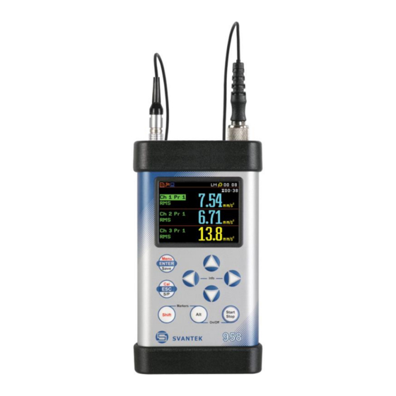
SVAN 958A User Manual 2 GENERAL INFORMATION 2.1 I NPUT AND OUTPUT SOCKETS OF THE INSTRUMENT Top cover of the instrument The measurement inputs are placed on the top cover of the instrument: 4-pins Lemo compatible socket type ENB.0B.304 for Channels 1–3 and TNC for Channel 4, all with IEPE power supply for the accelerometers or microphone preamplifiers. - Page 14 Note: Switch the power off before connecting the instrument to any other device (e.g. a printer or a Personal Computer). Front panel of the SVAN 958A instrument Rear panel of the SVAN 958A instrument Control of the instrument has been developed in a fully interactive manner. The user can operate the instrument by selecting the appropriate position from the selected Menu list.
-
Page 15: Powering Of The Instrument
2.2 P OWERING OF THE INSTRUMENT The SVAN 958A can be powered by one of the following sources: • External DC power source, SA 15 – 6 V DC ÷1 5 V DC (1.5 W) • SA 17A external battery pack – operation time > 24 h (option) •... -
Page 16: Control Keys On The Front Panel
SVAN 958A User Manual 2.3 C ONTROL KEYS ON THE FRONT PANEL The following control keys are located on the front panel of the instrument: • <ENTER>, (<Menu>), [<Save>], • <ESC>, (<Cal.>), [<S/P>], • <Shift>, [Markers] • <Alt>, [Markers] ▲, •... - Page 17 SVAN 958A User Manual up control of the instrument as the user has faster access to the most frequently used sub-lists for easy navigation. [<Save>] This key (pressed together with <Alt>) enables the user to save measurement results as a file in the instrument’s internal memory or on the USB memory stick.
- Page 18 SVAN 958A User Manual [▲, ▼] The ▲ / ▼ key pressed in conjunction (or in sequence) with <Alt> enable the user specifically • change the mode of result presentation; • change the year in the current date setup screen...
-
Page 19: Working With The Instrument
SVAN 958A User Manual 2.4 W ORKING WITH THE INSTRUMENT The instrument is controlled by means of nine keys on the keypad. Using these keys, one can access all available functions and change the value of all available parameters. The instrument is equipped with the super contrast OLED colour display (320 x 240 pixels), which displays the measurement results and the configuration menu. -
Page 20: Configuration Mode
SVAN 958A User Manual Starting measurement To start measurement, press the <Start> key. icon will appear, measurement will be performed with the current instrument settings, which are stored in the instrument’s internal memory. <Start> The time passed from the measurement start (elapsed time) is displayed in the... - Page 21 SVAN 958A User Manual Recent Items list A double pressing of the <Menu> key opens the list of recently accessed menu items - History. This enables accessing most frequently used lists of parameters quickly, without the necessity of passing through the whole menu path.
- Page 22 SVAN 958A User Manual List of options The option list consists of different options, from which only one may be selected. The selection of the option is performed in the following way. Highlight the desired option with the ▲ / ▼ key, mark it with the ► key and then press <ENTER>.
-
Page 23: Default Settings
SVAN 958A User Manual 2.5 D EFAULT SETTINGS The default settings (set up by the manufacturer) for the channels are as follows: Channel 1 - Vibration mode; 316 m/s range; HP1 weighting filter, 1.0 s RMS detector; Channel 2 - Vibration mode; 316 m/s range;... - Page 24 SVAN 958A User Manual “slope–” icon is displayed when the “slope+” icon is displayed when the “Slope+” “Slope-” trigger is waiting for a condition trigger is waiting for a condition fulfilment. The fulfilment. The icon appears alternately icon appears alternately with with the „measurement”, „logging”...
-
Page 25: Memory Organisation
SVAN 958A User Manual 2.7 M EMORY ORGANISATION All available measurement results can be stored in the internal FLASH type memory of the instrument (32 MB) or on the external USB Memory Stick. The internal memory of the instrument is divided into two separate parts. One part is dedicated for saving the result and setup files and its size is equal to 16 121 360 bytes. - Page 26 SVAN 958A User Manual The File menu is used for checking the contents of the memory and for operating on files such as: save, load, delete, create new catalogue and perform defragmentation etc. <ENT> The Device position in the Save list (path: <Menu>...
-
Page 27: Functions Of The Instrument - Function
SVAN 958A User Manual 3 FUNCTIONS OF THE INSTRUMENT – Function The Function list contains the elements that enable the user to select the measurement mode of the instrument and perform calibration of it’s measurement channels. In order to select the Function list the user has to press the <Menu>... -
Page 28: Activation Of Optional Functions
SVAN 958A User Manual 3.2 A CTIVATION OF OPTIONAL FUNCTIONS Optional measurement functions that broaden the application of the instrument can be easily installed. These options can be initially supplied by the manufacturer or purchased later and added by the user. -
Page 29: Calibration By Setting Transducer's Sensitivity - By Sensitivity
SVAN 958A User Manual Note: It is not possible to calibrate the instrument during the execution of the measurements. It is possible to open different lists and sub-lists but the positions in these lists are not displayed inversely and so - not accessible. The “play” icon indicates that the instrument is in the measurement process. -
Page 30: History Of The Calibrations - Calibration History
(the value of the Calibration Level set by the producer of SVAN 958A for sound is equal to 114 dB, and for vibration – to 1.00 m/s The measurement starts after 5 seconds delay. The calibration measurement time is also predefined to 5 seconds. - Page 31 SVAN 958A User Manual In order to review the calibration record, the user has to use the ▲ / ▼ key. The opened list will contain the date and time of the performed calibration measurement, the way the calibration was done (By Sensitivity or By Measurement) and the calibration factor (Cal.
-
Page 32: Measurement Parameters Setting - Input
SVAN 958A User Manual 4 MEASUREMENT PARAMETERS SETTING – Input The Input list contains the elements, which enable user programme measurement parameters for all channels and profiles. The Input list appears after pressing the <Menu> key, selecting the Input text and pressing <ENTER>. -
Page 33: Selection Of Measurement Parameters - Measurement Setup
SVAN 958A User Manual 4.1 S ELECTION OF MEASUREMENT PARAMETERS EASUREMENT ETUP The Measurement Setup list consists of the following parameters: the delay of start of the measurements (Start Delay), the integration period / measurement run time (Int. Period), the repetition of the measurement cycles... - Page 34 SVAN 958A User Manual Time period between two writings to the logger’s file The Logger Step defines the period of the data logging in a file. It can be set from 10 ms to 1 s in 1, 2, 5 sequence, the values from 1 second to 59 seconds, the values from 1 minute to 59 minute and 1 hour.
-
Page 35: Setting Parameters For Channels - Channels Setup
SVAN 958A User Manual – C 4.2 S ETTING PARAMETERS FOR CHANNELS HANNELS ETUP The Channels Setup position enables the user to program four channels of the instrument. <ENT> Note: Changing the channel parameters is not possible when the measurement is running. The user has to finish the current measurement. -
Page 36: Setting The Data Logging Functionality - Logger Setup
SVAN 958A User Manual In case of vibration measurements the following filters are available in the Filter position: - HP1, HP3, HP10, KB, Wk, Wd, Wc, Wj, Wm, Wh, Wg, Wb, Wv and Wz (for acceleration); - Vel1, Vel3, Vel10 and VelMF (for velocity);... - Page 37 SVAN 958A User Manual Selecting time-history results to be logged The Channel x (y) positions define results, which are to be saved in a logger file. The (y) value shows the number of selected results for each channel x. Up to five measurement results: PEAK, P–P, <ENT>...
-
Page 38: Setting Parameters Of Auxiliary Functions - Auxiliary Setup
SVAN 958A User Manual The results of the time-domain signal cannot be viewed in the instrument, but can be examined after downloading them to a PC using SvanPC software. The signal is saved in .svn format files. <ENT> – A 4.4 S... -
Page 39: Setting The Parameters Of Attenuation Measurements - "Seat" Setup
SVAN 958A User Manual Setting the parameters of attenuation measurements – “SEAT” Setup 4.4.2 The “SEAT” Setup option may be used for measurements of attenuation of vibration. channels (Base Channel) measures the signal before attenuation and other (Seat Channel) measures the signal after attenuation (e.g. - Page 40 SVAN 958A User Manual Note: When the HAV/WBV dosimeter is enabled the D letter appears before the function abbreviations (e.g. DLM, D1/1, DDos etc.) If filters of different type of integration are selected (for example HP and Vel), the “Vibration Dosimeter Off - Incorrect Dosimeter Settings” message appears on the display and the vibration dosimeter is switched off automatically.
-
Page 41: Triggering Mode And Parameters Selection - Trigger Setup
SVAN 958A User Manual – T 4.5 T RIGGERING MODE AND PARAMETERS SELECTION RIGGER ETUP The Trigger Setup sub-list enables the user to set the triggering parameters. <ENT> Measurement trigger setup – Measure Trigger 4.5.1 Switching the triggering on The triggering is switched on if one of its seven modes is selected: Slope +, Slope –, Level +,... -
Page 42: Logger Trigger Setup - Logger Trigger
SVAN 958A User Manual Selection of the triggering signal In the Source position four options are available: RMS(1), Ext. IO (in case of Slope + and Slope –), VEC/SND, Vector. In case of Grad + mode only the output signal from the RMS detector coming from the first profile of the selected channel can be used as a source of triggering signal (RMS(1)). -
Page 43: Alarm Trigger Setting - Alarm Trigger
SVAN 958A User Manual In the Logger Trigger sub-list the user may switch off or on (Enabled) the logger triggering, determine the parameters of the triggering signal (Select Source), select the number of the results saved in the logger before the fulfilment of the triggering condition (Pre) and the number of the results saved in the logger after the fulfilment of the triggering condition (Post). -
Page 44: Alarm On Sms Trigger Setting - Alarm Sms Notification
The Alarm SMS Notific. position enables the user to program the trigger, which generates an alarm SMS. This position is available for the SVAN 958A Firmware supporting modem. The Alarm SMS Notific. position opens the list with alarm events, defined in the <ENT>... - Page 45 SVAN 958A User Manual • if Slope + is selected, the triggering condition is fulfilled only when the rising value of Source is passing the level determined by Level. • if Slope – is selected, the triggering condition is fulfilled only when the falling value of Source is passing the level determined by Level.
- Page 46 SVAN 958A User Manual Selecting trigger actions The Trigger Actions Setup position enables the user to select the trigger actions for defined condition: Alarm, Send SMS, Send E-mail and Logger. If selected the trigger action will appear in the <ENT>...
-
Page 47: Data Available On The Display - Display
Modem Status enables the user to check the status of the modem. This position appears in the SVAN 958A Firmware supporting modem and when the GPRS function is switched on; Unit Label enables the user to check the type of the instrument, its serial number and the current software version installed and the standards the instrument fulfils. - Page 48 SVAN 958A User Manual The Logger presentation mode shows the time history of selected results. => 4-View presentation mode shows simultaneously results for all four channels. => When all display modes in the Display Modes list are switched on they all are available and can be selected by means of the <Alt>...
- Page 49 SVAN 958A User Manual Changing the field content When Profile or Function position is chosen, then the profile number or function name is changed by means of the ◄ and ► keys. ► Changing the presentation mode The presentation mode is changed after pressing the ▲ or ▼ key pressed together with <Alt>.
- Page 50 SVAN 958A User Manual Field description of the Statistics view Channel number Statistics plot Statistical level (LN% percentile value) for the active cursor position RMS detector (Lin., or Exp.: Fast, Slow or Imp.) Frequency filter used (A, C or Z)
-
Page 51: Setting The Parameters Of Graphical Presentations - Display Setup
SVAN 958A User Manual Changing the active fields Jumping between positions is made by means of the ▲ or ▼ keys. ▼ Changing the field content When Profile or Function position is chosen, then the profile number or function name is changed by means of the ◄... -
Page 52: Checking The Instrument Powering - Power Supply
SVAN 958A User Manual Scaling the vertical axis If Scale is set to Logarithmic then the Dynamic position enables the user to select the required dynamic range scaling of the graphical presentation mode. The user can obtain double, four times and eight times =>... -
Page 53: Checking The Modem Status - Modem Status
▲ and ▼. <ENT> Note: The contents of the Unit Label list should be always sent to Svantek local service department or official representative in case of any problems faced by the user during the instrument’s normal operation in the field. -
Page 54: Saving The Measurement Results - File
SVAN 958A User Manual 6 SAVING THE MEASUREMENT RESULTS – File The File list contains the elements that enable the user to manage the data files that are created and saved in the internal memory of the instrument. There are two main ways for storing the measurement data in the instrument: 1. -
Page 55: Saving Files In The Instruments Memory Or External Memory
SVAN 958A User Manual ’ 7.1 S AVING FILES IN THE INSTRUMENT S MEMORY OR EXTERNAL MEMORY There are two options for storing result data in the internal or external memory. One option is to press the <Save> key right after the measurement stop. -
Page 56: Controlling Data Storing In The Instruments Memory - Save Options
SVAN 958A User Manual Changing the edited character The available ASCII characters can be ▲ / ▼ changed using key. subsequent digits, letters and other characters appear on the display in the inversely displayed position after each press of the ▲... - Page 57 SVAN 958A User Manual The statistics are not calculated for the vibration measurements. Note: This position was created to save the memory of the instrument in the case when the knowledge of the statistics is not necessary. Each registration of the statistics requires 600 bytes...
-
Page 58: Loading Files With The Measurement Results - Load File
SVAN 958A User Manual Editing the name of the Auto Save file The Auto Name enables the user to edit the name of the Auto Save file. To edit the file name the user has to press the ► key. The text editing window is opened. -
Page 59: Removing File With The Measurement Results - Delete
SVAN 958A User Manual results in each channel (e.g.: (5)rvR means that from the first channel all five available logger results are stored in memory and, additionally, rpm, vector and spectrum (RMS) are also saved in the selected logger file). -
Page 60: Merging Result And Setup Files Memory - Defragmentation
SVAN 958A User Manual – D 7.7 M ERGING RESULT AND SETUP FILES MEMORY EFRAGMENTATION The Defragmentation option is used to make the Internal memory space contiguous. All new files are saved starting from the beginning of the free memory space. The memory occupied... -
Page 61: Saving Setup In The Instruments Memory - Save Setup
SVAN 958A User Manual ’ – S 7.10 S AVING SETUP IN THE INSTRUMENT S MEMORY ETUP The Save Setup position is used for storing setups in the FLASH DISC memory of the instrument as a file. The Save Setup window content is similar to the Save Results one. - Page 62 SVAN 958A User Manual To create the new catalogue the user should Action: Create New. After press <ENTER> the instrument will go to the Directory Name screen in which the user will be proposed edit the predefined catalogue name. <ENT>...
-
Page 63: Additional Settings - Setup
Wireless Com. enables the user to select the network type and set the parameters of the data transmission. This position is available for the SVAN 958A Firmware supporting modem. -
Page 64: Setting The Language Of The User Interface - Language
SVAN 958A User Manual – L 7.1 S ETTING THE LANGUAGE OF THE USER INTERFACE ANGUAGE The Language list enables the user to select the language of the user interface. For activation of the Russian version of the user interface, a special code has to be entered. -
Page 65: Selection Of The Extended Mode - Ext. I/O Setup
SVAN 958A User Manual – E 7.5 S . I/O S ELECTION OF THE EXTENDED MODE ETUP The Ext. I/O Setup enables the user to select the function of the instrument’s socket named as I/O. This socket can be used as: •... -
Page 66: Turning Off Instrument Due To Low External Voltage - Ext. Power Setup
SVAN 958A User Manual – E 7.6 T URNING OFF INSTRUMENT DUE TO LOW EXTERNAL VOLTAGE OWER ETUP The Ext. Power Setup item allows setting the minimum voltage of the external DC power source, when the instrument should be switched off automatically (Power Off) when the voltage of the external DC power source will be below the Limit level. -
Page 67: Locking The Menu - Menu Lock
SVAN 958A User Manual – M 7.8 L OCKING THE MENU The Menu Lock sub-list enables the user to lock (Partial or Full Lock) and unlock the menu. In the case of default No Lock option all available positions in the menu are accessible due to the settings, which were made. -
Page 68: Setting The Parameters Of The Serial Interface - Rs232 Setup
SVAN 958A User Manual The Linear option means that the values of LEQ or RMS based results don’t depend on the detector time constant (Detector). The Exponential option means that all LEQ or RMS based results will be measured with the selected detector time constant (Detector) –... -
Page 69: Selection Of Statistics Levels To Be Saved In A File - Statistical Levels
SVAN 958A User Manual – S 7.14 S ELECTION OF STATISTICS LEVELS TO BE SAVED IN A FILE TATISTICAL EVELS The Statistical Levels enables the user to select statistics from hundred calculated in the instrument, which are to be displayed and saved in a file together with the main results of the measurements. -
Page 70: Programming The Instruments Socket Named Usb Host - Usb Host Setup
SVAN 958A User Manual Example of Timer execution Let’s assume that you wish to switch on the instrument on the 1 of February, at 00:00, make measurement during 10 seconds without using logger and save the results in a file named @RE11. -
Page 71: Setting User Filter Coefficients For 1/1 Octave And 1/3 Octave Analysis - User Filters
SVAN 958A User Manual – 7.17 S 1/1 O 1/3 O ETTING USER FILTER COEFFICIENTS FOR CTAVE AND CTAVE ANALYSIS ILTERS The User Filters sub-list enables the user to introduce the values of the coefficients of the user defined frequency filters. This position is active only in 1/1 Octave and 1/3 Octave modes. -
Page 72: Warnings Selection - Warnings
– W 7.20 P ARAMETERS OF REMOTE COMMUNICATION IRELESS OMMUNICATION The Wireless Com. position enables the user to select the network type and set the parameters of the data transmission. This position appears in the SVAN 958A Firmware supporting modem. <ENT>... -
Page 73: Selection Of The Network Type - Network Setup
On (registration using Connection Request Packets), AS (periodic registration on Svantek Server Address), SMT.AS (registration on Svantek Server Address – performed each time internet connection is initialized by the modem). In case when Data Protocol type is TCP C the Register Type position does... -
Page 74: Setting Of Support Modem Options - Modem Connection
SVAN 958A User Manual • SIM Auth Mode – defines the method of user verification by the SIM card. Depending on the SIM card, several options are possible, some of them are recognized by the modem: • none – no verification required. -
Page 75: Configuration Of Sms Service - Sms Option
SVAN 958A User Manual • APN – allows the user to enter up to 20 characters of APN name of the SIM card used with the modem. • APN User – allows the user to enter up to 20 characters of user name used for verification by the SIM card used with the modem. - Page 76 SVAN 958A User Manual template used for alarm notification. Data Port – allows the user to enter up to 5 characters for the port • number. This number denotes a port on which a communication socket will be configured for data exchange between remote host and the...
-
Page 77: Calculation Of Dose Parameters - Auxiliary Functions
SVAN 958A User Manual 8 CALCULATION OF DOSE PARAMETERS – Auxiliary Functions The Auxiliary Functions list is used to calculate the various parameters, which are mainly dedicated for the control of the vibration measurements. This sub-list contains two positions: HAV Calculator and... - Page 78 SVAN 958A User Manual Selection of the daily exposure The Daily Results position is used to display Daily Exposure results, calculated from all partial results, saved in selected files. The result is calculated relatively to Exposure Time. <ENT>...
-
Page 79: Printing Reports - Report
SVAN 958A User Manual PRINTING REPORTS – Report The printed reports of the Sound or Vibration measurement results in the predefined format can be obtained by means of the Report list. The Report list contains the following elements: Title enables the user to edit the text added to the file and to the report to be printed;... -
Page 80: Edit The User Title Of The Report - Title
SVAN 958A User Manual Note: Switch the power off before connecting the instrument to any external device (e.g. a printer or a Personal Computer). Note: All reports are printed in the character format using the ASCII set on either A4 or A5 size paper. -
Page 81: Selection The Printing Options - Print Options
SVAN 958A User Manual – P 9.3 S ELECTION THE PRINTING OPTIONS RINT PTIONS The Options list enables the user to select the format of the listing (Page Size) and the way the paper is ejected in the printer (Eject Page). -
Page 82: 10 1/1 And 1/3 Octave Analyser
SVAN 958A User Manual 10 1/1 AND 1/3 OCTAVE ANALYSER The instrument operates as a real-time 1/1-octave or 1/3-octave analyser in a very similar way to the level meter and, in addition, 1/1-octave or 1/3-octave analysis is performed in parallel with the level meter measurements. -
Page 83: Selection Of 1/1 Octave And 1/3 Octave Bandpass Results As Triggering Source
SVAN 958A User Manual 1/1 Octave Setup (1/3 Octave Setup) position appears in the Input list when the 1/1 Octave (1/3 Octave) function is selected in the Measurement Function list and enales the user to select the parameters for 1/1 and 1/3 octave spectrum calculation for each channel: weigting filter and frequency band. - Page 84 SVAN 958A User Manual For the 1/1 Octave or 1/3 Octave functions additional 1/1 Octave or 1/3 Octave position appears in the Trigger Events list. These positions enable the user to define additional trigger events with the use of result of 1/1 or 1/3 analysys.
-
Page 85: Display Options In 1/1 Octave And 1/3 Octave Analysis Mode
SVAN 958A User Manual Threshold definition The Level position enables the user to select the value of threshold for triggering condition in therange of 60 dB to 200 dB for Sound input and of 1.00 mm/s to 10.0 km/ s for vibration input. -
Page 86: Setting The Scale Of The Spectrum Results Presentation - Display Scale
SVAN 958A User Manual Field description of the Spectrum view 1. Spectrum type/Channel number 2. Cursor position 3. Value for the cursor position 4. Used averaging 5. Spectrum plot 6. Frequency weighting filter 7. Type of spectrum 8. Total values 9. -
Page 87: Setting Parameters Of The Spectrum Presentation - Spectrum View
SVAN 958A User Manual Scaling the vertical axis If Scale is set to Logarithmic then the Dynamic position enables the user to select the required dynamic range scaling of the graphical presentation mode. The user can obtain double, four and eight times expansion =>... -
Page 88: Setting User Filter Coefficients For 1/1 And 1/3 Octave - User Filters Setup
SVAN 958A User Manual By default: For vibration input HP filter is denote for the first Total value. Second and third Totals have same filters as were set up for channel (CH) in the Channels list (path: <Menu> / Measurement / Channels). - Page 89 SVAN 958A User Manual The Edit position opens the list with the table of filter coefficients. All positions in this table can be edited by the user. <ENT> The opened list contains the centre frequencies of the filters and their coefficients: •...
-
Page 90: Dosimeter
SVAN 958A User Manual 11 DOSIMETER The instrument can operates as an acoustic Dosimeter, which function is supplementary to the Level Meter function. In the Dosimeter mode, basic dose results (DOSE, D_8h and LAV, E, E_8h) are calculated in parallel with the Level Meter results for channels with the Sound inputs. - Page 91 SVAN 958A User Manual The threshold level influences the calculations of the dosimeter results, namely DOSE, D_8h and LAV. The Threshold Level line is accessible after pressing the ▲ / ▼ key in the Dosimeter Setup list. The available values are as follows: None, 75 dB, 80 dB, 85 dB or 90 dB.
-
Page 92: Fft Analyser
SVAN 958A User Manual 12 FFT ANALYSER The instrument operates as the FFT analyser in a very similar way to the level meter. Moreover, the FFT analysis is performed in parallel with the level meter measurements. The results of FFT analysis (spectra) can be examined by the user on a display in the Spectrum presentation mode. - Page 93 SVAN 958A User Manual Weighting filter In the case of sound measurements there are HP, LIN, A and C filters available. In the case of vibration measurements, only HP filter is available and the position is not accessible after entering the FFT Setup list.
-
Page 94: Display Options In Fft Analysis Mode
SVAN 958A User Manual 12.3 D ISPLAY OPTIONS IN ANALYSIS MODE The Display Setup list is used for setting the various parameters which mainly dedicated for the control of the spectrum view. The following lists contain the elements that influence the presentation of the results of FFT analysis: <ENT>... -
Page 95: Setting The Scale Of The Spectrum Results Presentation - Display Scale
SVAN 958A User Manual The user may zoom in/out the frequency scale at the cursor position by means of the ◄ / ► key, pressed with <Shift>. <Sh/> – D 12.5 S ETTING THE SCALE OF THE SPECTRUM RESULTS PRESENTATION... -
Page 96: Cross-Spectrum
SVAN 958A User Manual 13 CROSS-SPECTRUM If the Cross Spectrum function is selected the instrument operates as the FFT analyser and the Level Meter and in addition performs calculation of cross-spectra. A cross spectrum is calculated for two signals measured in separate channels. In this function, the instrument... - Page 97 SVAN 958A User Manual The cursor position can be change by means of the ◄ / ► key. ►...
-
Page 98: Sound Intensity
SVAN 958A User Manual 14 SOUND INTENSITY If the Sound intensity function is selected the instrument operates as the FFT analyser and the Level Meter and in addition performs calculation of crosspower spectrum. The sound intensity measurement involves the use of two microphones located close to each other, normal to the direction of sound energy flow. -
Page 99: Reverberation Time
Z weighted). Whole measurement process and calculations implemented in the SVAN 958A instrument fulfil the ISO 3382 standard. The reverberation time of the room can be obtained with the use of the SVAN 958A instrument by two measurement methods: Impulse (Impulse Response Method) and Decay (Interrupted Noise Method). The selection of the method depends on the type of the sound source utilized by the user. - Page 100 SVAN 958A User Manual The Measurement Setup list enables the User to select the method for RT60 calculation, and other parameters for RT60 calculation. The Method position enables the user to choose the method for RT60 calculation: Decay or Impulse.
- Page 101 SVAN 958A User Manual <Start> <ENT> <ENT> The Clear Averages position enables the user to clear all previous averages and the averaging will start from next measurement. To clear averaging the user should select the field Clear Averages: x and press the <ENTER> key, select in the confirmation window Yes and press <ENTER>...
-
Page 102: Configuring Results View
SVAN 958A User Manual 15.3 C ONFIGURING RESULTS VIEW The Display Modes list of the Display menu enables the user to select the type of data displayed during the RT60 calculation. <ENT> Time data can be viewed as a Raw Data, Smooth Data (or Integrated Data in case of Impulse method). -
Page 103: Visualization Of The Rt 60 Measurements Results
SVAN 958A User Manual Note: It is necessary to switch on the sound source before starting the measurement because of the trigger requirements. If there it is necessary to start the instrument before switching on the sound source it is recommended to use the higher Start Delay value. - Page 104 SVAN 958A User Manual Table of RT60 results The table presents the results of reverberation time for different RT60 results: EDT - early decay time; RT 20 - reverberation time calculated with 20 dB dynamics; RT 30 - reverberation time calculated with 30 dB dynamics;...
- Page 105 SVAN 958A User Manual Sound pressure decay curve plot 1. Channel number 2. T0 marker position 3. Decay curve plot 4. T1 marker position 5. Type of data displayed: RAW, SMNH or INT. 6. Name of the logger file 7. Cursor position 8.
-
Page 106: Wave Recorder
SVAN 958A User Manual 16 WAVE RECORDER The Wave Recorder mode is an optional function of the SVAN 958A instrument, which is working in parallel with the Level Meter and additionally provides signal recording directly on the USB disc in the common used file format. -
Page 107: Appendix A. Remote Control (V4.16.2)
SVAN 958A User Manual Appendix A. REMOTE CONTROL (v4.16.2) The USB 1.1 interface is the serial one working with 12 MHz clock. Its speed is relatively high and it ensures the common usage of USB in all produced nowadays Personal Computers. - Page 108 SVAN 958A User Manual #1,Xccc,X?,Xccc,(...),X?,Xccc; where: X - the group code, ccc - the code value, X? - the request to send the current X code setting. The instrument will output a control settings file for all requests X? in the following format: #1,Xccc,Xccc,(...),Xccc;...
-
Page 109: Function #2 - Read-Out Of The Measurement Results In The Slm Or Vlm Mode
SVAN 958A User Manual #2 – A.3. F UNCTION READ OUT OF THE MEASUREMENT RESULTS IN THE MODE Function #2 enables one to read out the current measurement data in the SLM or VLM Mode. Note: This function can also be programmed while measurements are taking place. - Page 110 SVAN 958A User Manual B(k) the Lden result (ccc – the value in dB); the Ltm3 result (ccc – the value in dB); the Ltm5 result (ccc – the value in dB); L(nn) the value L of the nn statistics (ccc – the value in dB);...
- Page 111 SVAN 958A User Manual the SPL value (ccc – the value in dB); the DOSE value (ccc – the value in %); the DOSE8h value (ccc – the value in %); the LAV value (ccc – the value in dB);...
-
Page 112: Function #3 - Read-Out Of The Measurement Results In 1/1 Octave And 1/3 Octave Mode
SVAN 958A User Manual one should receive the following answer: #2,0,c-27.89,f-13.44,g172800,h172800,i172800,j172800; Note: All bytes of that transmission are ASCII characters. #3 – A.4. F 1/1 OCTAVE UNCTION READ OUT OF THE MEASUREMENT RESULTS IN 1/3 OCTAVE MODE Function #3 enables one to read out the current measurement data in 1/1 OCTAVE, 1/3 OCTAVE and FFT. -
Page 113: Function #4 - Read-Out Of The Data File From The Internal Flash-Disc And/Or The Special File Located In The Ram Memory
SVAN 958A User Manual #4 – A.5. F UNCTION READ OUT OF THE DATA FILE FROM THE INTERNAL FLASH DISC AND OR THE SPECIAL FILE LOCATED IN THE MEMORY Function #4 enables the user to read-out the data file from the internal Flash-disc memory. - Page 114 SVAN 958A User Manual #4,2,Bnnn; the file in internal memory containing logger, where nnn is the number of the logger file (one or more digits - depends on requirements). #4,3; the special file contained in the RAM memory (RAMfile), #4,3,?;...
-
Page 115: Function #5 - Read-Out Of The Statistical Analysis Results
SVAN 958A User Manual Note: If the DEFRAGMENTATION function is performed after the read out of the files catalogue the logical addresses of the files could be wrong. The measurement start date is coded as a word with bits: b15 ... b3 b2 b1 b0... -
Page 116: Function #6 - Remote Setting Of The User Filters
SVAN 958A User Manual Note: There is not any succeeding transmission in the case when the Status Byte is equal to 0. The transmission counter is a two-byte word denoting the number of the remaining bytes to be transmitted. Its value is calculated from the formulae:... - Page 117 SVAN 958A User Manual This function returns the list of the defined (existing in the instrument) filters in the following format: #6,type,n,name , ... ,name #6,type,W,name,v,v,...,v; This function sets the coefficients of the new user filter named as name. The name parameter should be unique (in the instrument there is not any other filter with the same name, otherwise it will be an error).
-
Page 118: Function #7 - Special Control Functions
SVAN 958A User Manual Note: In the case of an error all these functions return the following sequence of the characters: #6?; #7 – A.8. F UNCTION SPECIAL CONTROL FUNCTIONS Function #7 enables the user to perform special control functions. Some of them should be used with the extreme care. - Page 119 SVAN 958A User Manual This function is not accepted and not performed while the instrument is in the RUN state. #7,LP; This function returns last internal files flash page. #7,ME; This function returns total storage capacity in MB. #7,BP; This function returns last internal buffer flash page.
- Page 120 SVAN 958A User Manual #7,AN,FName; This function sets the name of the file for the Autosave function as the FName. The given name has to start with character contain more than characters. function returns the following sequence of characters: #7,AN;...
- Page 121 SVAN 958A User Manual This function sets usb host port mode to XX, where XX: 0 - OFF 1 - RS232 3 - USB DISC 5 - WAVE RECORDING #7,UP; This function returns usb host port mode in the format: #7,UP,XX;...
-
Page 122: Function #9 - Writing Setup Files To The Internal Flash-Disc
SVAN 958A User Manual This function returns state of automatic instrument shutdown function in case of low level of external power. #7,XP,1; is returned if function is active, #7,XP,0; otherwise. Function returns #7,XP; in case of success. #7,XP,n; This function sets state of automatic instrument shutdown function in case of low level of external power. n = 1 activates function, n = 0 disables this function #7,XL;... -
Page 123: Control Setting Codes
SVAN 958A User Manual The #9 function format is defined as follows: #9,2,Len,<data byte> ... <data byte> where: Len - length of transferred file in bytes as ASCII, <data byte> - byte of data in binary form. Function responds with “#9,1;” on success and with “#9,0;” on failure. - Page 124 SVAN 958A User Manual Execution of 1/1 OCTAVE, e0:n - Spectrum analysis in channel n disabled 1/3 OCTAVE or FFT analysis e1:n - Spectrum analysis in channel n enabled in channel n R1:n - Low (SLM) or Low (VLM) Range of channel n...
- Page 125 SVAN 958A User Manual I1:m HP1 filter for profile m I2:m HP3 filter for profile m I3:m HP10 filter for profile m I4:m Vel1 filter for profile m I5:m Vel3 filter for profile m I6:m Vel10 filter for profile m...
- Page 126 SVAN 958A User Manual B0:m - None logger in profile m Bxx:m - xx - sum of values for profile m: 1 – logger with PEAK values Logger type in profile in the case 2 – logger with MAX values of SLM 4 –...
- Page 127 SVAN 958A User Manual u0:n - 1920 lines in channel n Lines in FFT analysis in channel n u1:n - 960 lines in channel n u2:n - 480 lines in channel n w0:n - HANNING in channel n Window in the FFT analysis...
- Page 128 SVAN 958A User Manual Number of the records from the qnn - number of the records taken into account logger taken into account after the after the fulfilment of the triggering condition fulfilment of the triggering condition (0 ÷ 200) (TriggerPost) nn delay given in milliseconds (0 ÷...
- Page 129 SVAN 958A User Manual XG0 - Great Britain XG1 - Italy XG2 - Poland Vibration dose standard XG3 - French XG4 - user defined XG5 - Germany XG6 - China X axis for vibration dose n - channel number (1..4)
- Page 130 SVAN 958A User Manual Function for Digital In AC/Int. mode XP0 - trigger pulse XQ0 - trigger pulse Function for Digital Out AC/Int. mode XQ1 - alarm pulse XU0 - positive AC/Int. polarization XU1 - negative XV0 - active low AC/Int.
- Page 131 SVAN 958A User Manual Xk0:P:K - logger step Xk1:P:K - 100 ms Xk2:P:K - 1 s Integration period for VLM profile Xk3:P:K - current alarm Xk4:P:K - integration period P - profile number K - number of alarm in profile...
- Page 132 SVAN 958A User Manual XXa0:P:K - OFF XXa1:P:K - LEVEL - XXa2:P:K - LEVEL + XXa3:P:K - SLOPE - 1/1 OCTAVE alarm mode for VLM XXa4:P:K - SLOPE + XXa5:P:K - GRADIENT - XXa6:P:K - GRADIENT + P - channel number...
- Page 133 SVAN 958A User Manual XXf11:P:K - 1 Hz band 1/1 OCTAVE alarm source for SLM XXf25:P:K - 16 kHz band P - channel number K - number of alarm in channel XXgN:P:K - N – level in dB*10 1/1 OCTAVE alarm level for VLM...
- Page 134 SVAN 958A User Manual XXD0:P:K - logger step XXD1:P:K - 100 ms XXD2:P:K - 1 s 1/3 OCTAVE alarm period for SLM XXD3:P:K - current XXD4:P:K - integration period P - channel number K - number of alarm in channel XXE11:P:K - 0.8 Hz band...
- Page 135 SVAN 958A User Manual XXXo0 - 100 ms detector XXXo1 - 125 ms detector XXXo2 - 200 ms detector GROUND VIBRATIONS 2nd profile XXXo3 - 500 ms detector XXXo detector XXXo4 - 1 s detector XXXo5 - 2 s detector...
- Page 136 SVAN 958A User Manual 1/1 octave trigger actions in VLM mode XXi0:P:K - None logger in profile XXiNN:P:K - NN - sum of values: 1 – alarm signal 2 – start logging vOctTrgAct 4 – start wave recording 8 –...
- Page 137 SVAN 958A User Manual modem autoconfiguration modem autoconf XXo0 - OFF XXo1 - ON XXr0 - none XXr1 - PAP SIM auth mode XXr2 - CHAP XXr3 - MsCHAP modem connection type XXq0 - TCP server modem connType XXq1 - TCP client...
- Page 138 SVAN 958A User Manual 1/3 octave trigger gradient level in SLM mode XXZN:P:K - N – gradient level in dB sTerTrgGradLvl channel number number of alarm in channel email server address XXXasss - sss - address string XXXa email server login...
-
Page 139: Appendix B. Data File Structures (V4.16)
FILE Each file containing data from the SVAN 95x instrument consists of several groups of words. In the case of the SVAN 958A there are some different types of files that contain: • the measurement results from the Level Meter mode (cf. App. B.2);... - Page 140 SVAN 958A User Manual • the logger header (cf. Tab. B.1.22); • the 1/1 OCTAVE or 1/3 OCTAVE logger header (cf. Tab. B.1.23); • the data stored during the measurements in the logger (cf. Tab. B.1.24); • the setup data of the instrument (cf. Tab. B.1.26);...
- Page 141 SVAN 958A User Manual Table B.1.2. Unit and software specification Word Name / Value Comment number 0xnn02 [02, nn=specification_length] UnitNumber unit number. If 0 unit number is in the UnitNumber32 field UnitType unit type: 958 SoftwareVersion software version * 100...
- Page 142 SVAN 958A User Manual flags word (16 bits): b15 ... b3 b2 b1 b0 b0 - if set to 1: calibration coefficient is used b1 - if set to 1: overload occurred b2 - if set to 1: "Human vibrations" excluded (0 - means "Human vibrations"...
- Page 143 SVAN 958A User Manual number of the records taken into account before the fulfilment LoggerTriggerPre of the triggering condition (1 20) number of the records taken into account after the fulfilment LoggerTriggerPost of the triggering condition (1 200)
- Page 144 SVAN 958A User Manual mode of the 1 channel ChannelMode[1] 0 - Vibration Level Meter / Analyser 1 - Sound Level Meter / Analyser CalibrFactor[1] calibration factor (*10 dB) in the 1 channel range in the 1 channel Range[1] in the case of SLM: 1 - Low, 2 - High...
- Page 145 SVAN 958A User Manual outdoor correction of direction: MicOutdoorDir[3] 0 - airport 1 - environment 0x0706 [06, 08=subblock_length] mode of the 4 channel: ChannelMode[4] 0 - Vibration Level Meter / Analyser 1 - Sound Level Meter / Analyser CalibrFactor[4] calibration factor (*10 dB) in the 4...
- Page 146 SVAN 958A User Manual the 2 profile settings for the 2 channel, defined 32..37 ProfileSett[6] in the case of SLM mode - in Table B.1.5_SLM and in the case of VLM mode - in Table B.1.5_VLM the 2 profile settings for the 3 channel, defined in the case of SLM mode - in Table B.1.5_SLM and...
- Page 147 SVAN 958A User Manual Table B.1.5_VLM. Software settings for a channel in the case of VLM mode Word Name / Value Comment number 0xnn08 [08, nn=sub-block_length] ChannelNo channel number: 0 - the 1 channel filter type in the channel: 1 - HP1, 2 - HP3, 3 - HP10, 4 - Vel1,...
- Page 148 SVAN 958A User Manual Table B.1.7. Octave analysis header Word Name / Value Comment number 0xnn09 [09, nn=block_length] 0xkknn [nn=spectrum_mask, kk=used_spectrum] header of the first enabled octave analysis, defined 2..5 OctaveHead[1] in the case of SLM mode - in Table B.1.7_SLM and in the case of VLM mode - in Table B.1.7_VLM...
- Page 149 SVAN 958A User Manual header of the first enabled FFT analysis, defined 2..13 FFTHeader[1] in the case of SLM mode - in Table B.1.8_SLM and in the case of VLM mode - in Table B.1.8_VLM … … … 2+spectrum header of the last enabled FFT analysis, defined _count*12..
- Page 150 SVAN 958A User Manual NFftTot number of TOTAL lines in the spectrum = 1 band of the FFT analysis: 1 - 22.4 kHz, 2 - 11.2 kHz, 3 - 5.6 kHz, FftBand 4 - 2.8 kHz, 5 - 1.4 kHz, 6 - 700 Hz, 7 - 350 Hz, 8 - 175 Hz, 9 - 87.5 Hz...
- Page 151 SVAN 958A User Manual main results from the 1 profile of the 1 channel, defined 2..15 MainResults[1] in the case of SLM mode - in Table B.1.10_SLM and in the case of VLM mode - in Table B.1.10_VLM main results from the 1...
- Page 152 SVAN 958A User Manual Lden value in the profile (*100 dB) Result[6] (depends on UnitFlags bits: b3, b4, b5) Result[7] LEQ value in the profile (*100 dB) Result[8] Ltm3 value in the profile (*100 dB) Result[9] Ltm5 value in the profile (*100 dB)
- Page 153 SVAN 958A User Manual N8 value for the LN8 statistics (1 99) N9 value for the LN9 statistics (1 99) N10 value for the LN10 statistics (1 99) LN1[1] value of the LN1 statistics (*10 dB) for the 1...
- Page 154 SVAN 958A User Manual Note: The TOTAL values, calculated in the case of sound measurements, correspond to the A, C and LIN filters – respectively. The TOTAL values, calculated in the case of vibration measurements, correspond to the HP, CH and CH filters – respectively, where CH denotes the filter used in the channel for Level Meter measurement.
- Page 155 SVAN 958A User Manual Table B.1.16. TOTALS description Word Name / Value Comment number 0xnn1A [1A, nn=block_length = 1+(1 + Ntotal*4)*k (words)] 1... one-channel totals description block first channel OneChnlTotDesc[1] 1+4*Ntotal with TOTALS in user filters (Table B.1.15.) … …...
- Page 156 SVAN 958A User Manual BottomClass[1] bottom class boundary (*10 dB) in the 1 channel ClassWidth[1] class width (*10 dB) in the 1 channel … … … block_ 0x0413 [13, 04=sub-block_length] length-4 block_ NofClasses[used_ number of classes in the last channel...
- Page 157 SVAN 958A User Manual Table B.1.21. Results of statistical analysis performed in 1/1 or 1/3 OCTAVE mode in one-channel Word Name / Value Comment number 0x0016 [16, 00=block length in next word] BlockLength BlockLength=2*NofHist*NofClass+6 number of histogramms (number of 1/1 OCTAVE or 1/3 OCTAVE...
- Page 158 SVAN 958A User Manual Note: The current logger time step in seconds can be obtained from the formulae: T = BuffTSec + BuffTMilisec / 1000. Table B.1.23. Spectrum header of the file from the logger Word Name / Value Comment...
- Page 159 SVAN 958A User Manual Table B.1.26. Data block of instrument’s setup Word number Name / Value Comment 0x0020 [20, 00=block length in the next word] BlockLength block length 2..BlockLength-1 SetupData saved setup values … … … Table B.1.27. User filters block in data file of instrument’s setup...
- Page 160 SVAN 958A User Manual Table B.1.29. Settings for RT60 measurement Word Name / Value Comment number 0xnn24 [24, nn=block length] Reserved reserved RT60Method measurement method: 1 - decay, 2 - impulse RT60Spectrum 2 - 1/3 OCTAVE analysis Buffer step time resolution of the logger results [ms]...
- Page 161 SVAN 958A User Manual BlockLen-4 cor_edt[LastRT60Freq+NTot] EDT correlation ratio BlockLen-3 RT 20 correlation ratio cor_rt20[LastRT60Freq+NTot] BlockLen-2 RT 30 correlation ratio cor_rt30[LastRT60Freq+NTot] BlockLen-1 cor_rt_user[LastRT60Freq+NTot] RT USER correlation ratio … … … Table B.1.31. Averaged RT60 measurement results in one channel Word...
- Page 162 SVAN 958A User Manual Table B.1.32. Results of one RT60 measurement averaged between channels Word Name / Value Comment number 0x0028 [28, 00=block length in the next word] BlockLen block length LowestFreq the lowest 1/3 octave frequency (*100 Hz) NTer...
- Page 163 SVAN 958A User Manual rt20(FirstRT60Freq) RT 20 result in ms rt30(FirstRT60Freq) RT 30 result in ms rt_user[FirstRT60Freq] RT USER result in ms n_edt[FirstRT60Freq] number of averaged EDT results n_rt20[FirstRT60Freq] number of averaged RT 20 results number of averaged RT 30 results...
- Page 164 SVAN 958A User Manual sampling rate: 0 - 3000 Hz 1 - 2400 Hz 2 - 1500 Hz 3 - 1200 Hz SampleRate 4 - 750 Hz 5 - 600 Hz 6 - 375 Hz 7 - 300 Hz 8 - 187 Hz 9 - 150 Hz 3..4...
- Page 165 SVAN 958A User Manual Table B.1.38. Minimum results of 1/1 OCTAVE analysis in one channel Word Name / Value Comment number 0xnn2E [2E, nn=block length] LowestFreq the lowest 1/1 OCTAVE frequency (*100 Hz) Noct number of 1/1 OCTAVE values NoctTot number of TOTAL values = 3 …...
- Page 166 SVAN 958A User Manual Table B.1.41. Trigger settings Word Name / Value Comment number 0x0031 [31, 00=block length in the next word] BlockLen block length NProfileTriggers number of trigger conditions per profile NSpectTriggers number of trigger conditions per spectrum channel VectorCondidtion vector trigger block (table B.1.42)
- Page 167 SVAN 958A User Manual Table B.1.43. FFT cross-spectrum settings Word Name / Value Comment number 0xnn34 [34, nn=block length] RefChannel reference channel Nval number of spectrum values 3..6 CSEnabled cross-spectrum enabled for channel from 1 to 4 7..8 CSTabPopr1 correction value for the 1 channel in dB*100 9..10...
-
Page 168: Structure Of The Block With Meteorological Data
SVAN 958A User Manual Table B.1.46. Peak results of 1/1 OCTAVE analysis in one channel Word Name / Value Comment number 0xnn38 [38, nn=block length] LowestFreq the lowest 1/1 OCTAVE frequency (*100 Hz) Noct number of 1/1 OCTAVE values NoctTot number of TOTAL values = 3 …... -
Page 169: Structure Of The File With The Results From Level Meter And Wave Recorder Modes
SVAN 958A User Manual Pressure pressure [hPa] Humidity humidity [*10%] WindSpeed wind speed [*10m/s WindDirection wind direction [degrees]. 0xFFFF if direction is unavailable 12..13 WindDirTotalPuffs number of total wind puffs in distribution vector of wind direction number of elements in distribution vector of wind direction NofWindDir 15.. -
Page 170: Structure Of The File With 1/1 Octave Analysis Results
SVAN 958A User Manual B.4 S 1/1 OCTAVE TRUCTURE OF THE FILE WITH ANALYSIS RESULTS File header - cf. Tab. B.1.1. Unit and software specification - cf. Tab. B.1.2. Parameters and global settings - cf. Tab. B.1.3. Hardware settings for channels - cf. Tab. B.1.4. -
Page 171: Structure Of The File With Fft Analysis Results
SVAN 958A User Manual Settings for vibration dose measurement (the presence depends on the MEASURE DOSE and channel filter settings) - cf. Tab. B.1.9. Main results - cf. Tab. B.1.10. RPM results (present if RPM measurement was enabled) - cf. Tab. B.1.34. -
Page 172: Structure Of The File Containing Lm Results From Loggers File
SVAN 958A User Manual ’ B.7. S TRUCTURE OF THE FILE CONTAINING RESULTS FROM LOGGER S FILE File header - cf. Tab. B.1.1. Unit and software specification - cf. Tab. B.1.2. Parameters and global settings - cf. Tab. B.1.3. Hardware settings for channels - cf. Tab. B.1.4. -
Page 173: Structure Of The File Containing Saved Instruments Setup
SVAN 958A User Manual Contents of the file from the logger - cf. Tab.B.1.24. File end marker - cf. Tab. B.1.25. ’ B.10. S TRUCTURE OF THE FILE CONTAINING SAVED INSTRUMENT S SETUP File header - cf. Tab. B.1.1. Unit and software specification - cf. Tab. B.1.2. -
Page 174: Structure Of The Logger File Containing Time-Domain Signal
SVAN 958A User Manual B.13. S TRUCTURE OF THE LOGGER FILE CONTAINING TIME DOMAIN SIGNAL File header - cf. Tab. B.1.1. Unit and software specification - cf. Tab. B.1.2. Parameters and global settings - cf. Tab. B.1.3. Hardware settings for channels - cf. Tab. B.1.4. -
Page 175: Contents Of The File In The Logger
SVAN 958A User Manual Trigger settings (cf. Tab. B.1.41, Tab.B.1.42). Vector measurement settings - cf. Tab. B.1.6. FFT analysis header - cf. Tab.B.1.8. Settings for vibration dose measurement (the presence depends on the MEASURE DOSE and channel filter settings) - cf. Tab. B.1.9. - Page 176 SVAN 958A User Manual PROF. 1 (path: MENU / INPUT / LOGGER SETUP / CHANNEL 2 / CHAN. 2 PROF. 1) sub-list was selected, up to five words are written in the given sequence: <result1> - PEAK result in the case of VLM or in the case of SLM if the first position was marked, else no value is written;...
- Page 177 SVAN 958A User Manual <result5> - VDV result in the case of VLM if the fifth position was marked, else no value is written; • results of the measurement from the 2 profile of the 2 channel if the LOGGER MODE was set to ON (path: MENU / INPUT / LOGGER SETUP / LOGGER MODE:ON);...
- Page 178 SVAN 958A User Manual • results of the measurement from the 3 profile of the 2 channel if the LOGGER MODE was set to ON (path: MENU / INPUT / LOGGER SETUP / LOGGER MODE:ON); and if any position in CHAN. 2 PROF.
- Page 179 SVAN 958A User Manual Octave[i] - the result of 1/1 OCTAVE analysis (*10 dB); i = 1..NOct+NOctTot (1..18) • results of 1/1 OCTAVE analysis from the 3 channel if 1/1 OCTAVE analysis was selected as the measurement function and in the LOGGER (path: MENU / INPUT / 1/1 OCTAVE SETUP / CHANNEL 3 ...
-
Page 180: Record With The State Of The Markers
SVAN 958A User Manual flags = 1 - the overload detected, 0 - the overload not detected Terave[i] - the result of 1/3 OCTAVE analysis (*10 dB); i = 1..NT (1..48 or 1..33) • results of FFT analysis from the 1 channel if FFT analysis was selected as the measurement function ... -
Page 181: Record With The Breaks In The Results Registration
SVAN 958A User Manual in which 12 bits nnn denote the state of the markers: b11 = state of #12 marker b10 = state of #11 marker b1 = state of #2 marker b0 = state of #1 marker B.16.3. Record with the breaks in the results registration The record with the breaks in the results registration consists of four words: <0xB0ii>... -
Page 182: Date And Time
SVAN 958A User Manual • Sample from the 3 channel if CHANNEL 3 was set to ON (path: MENU / INPUT / LOGGER SETUP / CHANNEL 3). The sample is written on three consecutive bytes from least to most significant byte. -
Page 183: Appendix C. Svan 958A Technical Specifications
Statement of performance SVAN 958A working as the SLM with all listed below accessories meets requirements of the IEC 61672-1:2013 for the Class 1 Group X instruments. SLM function is provided by the TNC/IEPE inputs using the SC 26 cable for Channel 4 and the SC 49 cable providing LEMO 4-pins to 3 x TNC connection for Channels 1-3. - Page 184 Battery state indication Normal operating mode SVAN 958A in configuration with the SV 12L microphone preamplifier, MK 255 microphone for each channel and the SC 26 extension cable for Channel 4 or SC 49 cable for Channels 1-3 and with following settings: High or Low measurement range, microphone compensation set to Free Field (path: <Menu>...
- Page 185 SVAN 958A User Manual Linear operating ranges for LEQ measurements with the Free Field compensation Two measuring ranges are available: Low and High. The starting point at which tests of level linearity shall begin is 94.0 dB for the frequencies specifies below. For the Low measurement range and A weighting linearity test at 31.5 Hz, the starting point is 69 dB.
- Page 186 SA 277C for the 0 deg incidence angle (see sections C.7 and C.8) Note: SVAN 958A and the MK 255 microphone are used to perform the measurements in the free field. In order to measure in the diffuse field or with the use of the SA 277C outdoor microphone kit, the user should select the appropriate compensation filter (see Chapter 4.2).
- Page 187 SVAN 958A User Manual Table C.1.4. Linear operating ranges for the Diffuse filter and Low measurement range (for the sinusoidal signal and microphone sensitivity 50 mV/Pa) AS/F CS/F LINS/F AeqT CeqT Cpeak = 2 s) [dB] from from from from...
- Page 188 <Start> (Reset) key and beginning of a new measurement Note: When SVAN 958A is moved from a warm environment with high humidity to a colder environment, care should be taken not to produce condensation inside the instrument. In this case,...
- Page 189 SVAN 958A User Manual Environmental, electrostatic and radio frequency criteria for all channels Effect of humidity < 0.5 dB (for 30%<RH<90% at 40C and 1000 Hz) Effect of magnetic field < 15 dB (A) or < 25 dB (Z) (for 80 A/m and 50 Hz) Effect of radio frequency fields <...
- Page 190 SVAN 958A User Manual Note: Maximum sound pressure level that can be applied to a microphone without destroying it: 146 dB. Typical MK 255 Free Field frequency response (source: Microtech Gefell Gmbh) Table C.1.6. MK 255 free field corrections using the electrostatic actuator for 0 deg incidence angle...
- Page 191 SVAN 958A User Manual Preamplifier SV 12L nominal preamplifier attenuation: 0.7 dB; IEPE Type – power supply 1.5 mA@30 V SV12L typical frequency response Effect of the SC26 extension cable of 3- and 10-meters length f [Hz] with preamplifier SC26 3m...
-
Page 192: Effect Of Vibration
Table C.1.8. Test conditions: The microphone type MK 255 and the preamplifier type SV 12L connected to SVAN 958A were mounted on the shaker. Ref 1. Vibration is applied in a direction perpendicular to the plane of the microphone diaphragm. -
Page 193: Effect Of The Sa 277C Outdoor Microphone Kit (Channel 4 Only)
SVAN 958A User Manual C.1.3. Effect of the SA 277C outdoor microphone kit (Channel 4 only) See Chapter C.7 for the details related to using of the SA 277C outdoor microphone kit. C.1.4. Effect of the SA 277D outdoor microphone kit (Channel 4 only) -
Page 194: Specification Of Svan 958A As Vibration Level Meter (Vlm)
Note: System conforms to the ISO 8041-1:2016, ISO 2631-1:1997, ISO 2631-2:2003, DIN 45669- 1:2010 standards. Normal operating mode SVAN 958A in configuration with the supplied accelerometer with following settings: High or Low measurement range (path: <Menu> / Channel Setup / Channel x – see Chapter 4.2) Measured quantities The measured quantities in the vibration meter mode are: RMS, VDV, OVL, PEAK, P–P, MTVV or MAX. - Page 195 SVAN 958A User Manual Conformance testing This chapter contains the information needed to conduct conformance testing according to the specified standards. Mounting for vibration tests The accelerometer can be connected with the VLM using proper cable provided by the manufacturer.
- Page 196 SVAN 958A User Manual Linear operating ranges (for acceleration) SVAN 958A uses two measurement ranges: Low and High. Values of the measured acceleration using the accelerometer with the nominal sensitivity equal to 10 mV/ms (e.g. the SV 39A/L seat accelerometer): •...
- Page 197 SVAN 958A User Manual Values of the measured acceleration using the accelerometer with the nominal sensitivity equal to 1 mV/ms (e.g. 3023M2): • Linear measurement with the Wh filter: the linear operating ranges for the distance from noise > 6 dB from 0.01 ms...
- Page 198 177 dB related to 1 µm/s Maximum input voltage SVAN 958A is the instrument with the 2 security class according to the international standard IEC 348. The input voltage should be within the interval from 0 V to 28 V.
- Page 199 SVAN 958A User Manual Overload detector The instrument has the built-in overload detectors. Both A/D converter and input amplifier overload conditions are detected. The overload in the measurement channel (in its analogue part) and the overload of the analogue / digital converter are both detected. The “overload” indication appears when the input signal amplitude is 0.5 dB above the declared “Peak measurement range”.
- Page 200 SVAN 958A User Manual Table C.2.9. Typical noise level of the VLM with accelerometers Type 3143M1, nominal Type 3023M2, nominal Filter sensitivity 10 mV/ms sensitivity 1 mV/ms 8,4 mm/s 107,0 mm/s 8,1 mm/s 84,5 mm/s HP10 8,0 mm/s 77,7 mm/s...
- Page 201 SVAN 958A User Manual Effect of electrostatic discharge (meets requirements of the ISO 8041-1:2017) During electrostatic discharge, the influence of the displayed results could be observed. No changes in instrument operation state, configuration or stored data corruption were found out.
-
Page 202: Specification Of Svan 958A As 1/1, 1/3 Octave And Fft Analyser
(input impedance 18 pF) Normal operating mode SVAN 958A in configuration with the SV 12L microphone preamplifier, ST 02 adapter for all channels and the additional SC 49 cable for Channels 1-3 and with following settings: High or Low measurement range, microphone compensation set to Free Field (path: <Menu>... - Page 203 SVAN 958A User Manual 1/1 octave and 1/3 octave filters 1/1 Octave 15 filters with centre frequencies from 1 Hz to 16 kHz (base 2). meeting DIN 45651. IEC 1260 (Annex B) and ANSI S1.11-1986 for Type 1 1/3 Octave 45 filters with centre frequencies from 0.8 Hz to 20 kHz (base 2).
- Page 204 SVAN 958A User Manual Maximum input voltage SVAN 958A meets the requirements IEC 348 for the 2 class device. The input voltage shall not exceed the limits between 0 V and 28 V. RMS detector “True RMS“ with PEAK detection...
-
Page 205: Specification Of Svan 958A As 1/1, 1/3 Octave And Fft Analyser In The Standard
C.3.2 Specification of SVAN 958A as 1/1, 1/3 octave and FFT analyser in the standard configuration for vibration inputs SVAN 958A performs the 1/1, 1/3 and FFT analysis for the VLM function in the configuration and with the parameters presented in Chapter C.2. -
Page 206: 1/1 And 1/3 Octave Filters Characteristics
< 80 dB @ 1 kHz C.3.3 1/1 and 1/3 octave filters characteristics 1/1 Octave 15 filters with centre frequencies from 1 Hz to 16 kHz (base 2). meeting DIN 45651, IEC 61260:1995 and ANSI S1.11-1986 for Class 1 SVAN 958A 1/1 octave filters characteristic... - Page 207 SVAN 958A User Manual Typical electrical noise floor for the 1/1 octave filters 1/3 octave filters 45 filters with centre frequencies from 0.8 Hz to 20 kHz (base 2), meeting DIN 45651, IEC 61260:1995 and ANSI S1.11-1986 for Class 1...
- Page 208 SVAN 958A User Manual 1/3 octave filters characteristic – “middle” filter for each octave band 1/3 octave filters characteristic – “upper” filter for each octave band Typical electrical noise floor for the 1/3 octave filters...
-
Page 209: Digital Hp Filter Implemented In 1/1 & 1/3 Octave And Fft Analysis
SVAN 958A User Manual C.3.4. Digital HP filter implemented in 1/1 & 1/3 OCTAVE and FFT analysis “HP” filter characteristics C.3.5. FFT analysis specification 1920, 960 or 480 lines of the power spectrum calculated in real time. Sampling frequency 48 kHz (internal only) - Page 210 SVAN 958A User Manual Table C.3.3. FFT analysis for the 480 lines spectrum (no-logging) FFT bandwith Record length Frequency resolution Overlapping factor [Hz} (samples) [Hz] 22 400 1024 46.875 11 200 1024 23.4375 5 600 1024 11.71875 2 800 1024 5.859375...
- Page 211 SVAN 958A User Manual FFT calculation time step (with spectra logging) for 1920 lines, 100 ms for 960 lines, 50 ms for 480 lines. 20 ms Table C.3.6. FFT analysis for the 480 lines spectrum (with logging) FFT bandwith Record length...
- Page 212 SVAN 958A User Manual Table C.3.8. FFT analysis for the 1920 lines spectrum (with logging) FFT bandwith Record length Frequency resolution Overlapping factor [Hz} (samples) [Hz] 22 400 4096 11.71875 11 200 4096 5.859375 5 600 4096 2.9296875 2 800 4096 1.46484375...
-
Page 213: Frequency Characteristics Of Implemented Broadband Digital Filters
SVAN 958A User Manual C.4. F REQUENCY CHARACTERISTICS OF IMPLEMENTED BROADBAND DIGITAL FILTERS C.4.1. Digital weighting filters dedicated for sound input “A” filter Class 1 according to IEC 651 and IEC 61672-1:2013 “A” filter characteristics “C” filter Class 1 according to IEC 651 and IEC 61672-1:2013... - Page 214 SVAN 958A User Manual “G” filter Class 1 according to ISO 7196 “G” filter characteristics LIN: cut-off frequency: 10.0 Hz / -3.0 dB. “LIN” filter characteristics...
-
Page 215: Digital Weighting Filters Dedicated For Vibration Inputs
SVAN 958A User Manual C.4.2 Digital weighting filters dedicated for vibration inputs HP1 filter is used for the acceleration measurements (the vibration signal) in the frequency range from 1 Hz to 20 kHz. “HP1” filter characteristics HP3 filter is used for the acceleration measurements (the vibration signal) in the frequency range from 3.5 Hz to 20 kHz. - Page 216 SVAN 958A User Manual HP10 filter is used for the acceleration measurements (the vibration signal) in the frequency range from 10 Hz to 20 kHz. “HP10” filter characteristics “Vel1” filter is used for the velocity measurements (vibration signal) in the frequency range from 1 Hz to 20 kHz ”Vel1”...
- Page 217 SVAN 958A User Manual Vel3 filter is used for the velocity measurements in the frequency range from 1 Hz to 20 kHz. ”Vel3” filter characteristics Vel10 filter is used for the velocity measurements in the frequency range from 1 Hz to 20 kHz.
- Page 218 SVAN 958A User Manual VelMF filter is used for the evaluation of the state of the machines. This filter is used for the measurements in the frequency range from 10 Hz to 1000 Hz and conforms to the ISO 10816 standard.
- Page 219 SVAN 958A User Manual Dil3 filter is used for the displacement measurements in the frequency range [1 Hz to 20 kHz]. ”Dil3” filter characteristics Dil10 filter is used for the displacement measurements in the frequency range [1 Hz to 20 kHz].
- Page 220 SVAN 958A User Manual Wk filter is used for the assessment of the influence of the vibration signal on the human body in the z direction and for vertical recumbent direction. It conforms with ISO 2631-1-97 and ISO 8041-1:2017 “Wk” filter characteristics Wd filter is used for the assessment of the influence of the vibration signal on the human body in the x and y directions and for horizontal recumbent direction.
- Page 221 SVAN 958A User Manual filter is used for the assessment of the influence of the vibration signal on the human body during the seat- back measurements. It conforms with ISO 2631-1-97 and ISO 8041-1:2017 “Wc” filter characteristics Wj filter is used for the assessment of the influence of the vibration signal under the head of the recumbent person.
- Page 222 SVAN 958A User Manual Wm filter is used for the assessment of the influence of the vibration signal on the human body. It conforms with ISO 2631-1-97 and ISO 8041-1:2017 “Wm” filter characteristics Wg filter is used for the assessment of the influence of the vibration signal on the human body. It conforms with BS 6841:1987 “Wg”...
- Page 223 SVAN 958A User Manual Wb filter is used for the assessment of the influence of the vibration signal on the human body. It conforms with ISO/FDIS 8041:2004(E) “Wb” filter characteristics KB filter is used for the building vibration measurements) according DIN 4150 standard...
-
Page 224: Miscellaneous Specification Of Svan 958A
SVAN 958A User Manual C.5. M SVAN 958A ISCELLANEOUS SPECIFICATION OF Display Super contrast (10000:1) OLED 2.4” colour display (320 x 240 pixels). Memory 32 MB flash memory and 96 kB of the RAM memory. Flash memory divided between: • buffer for the registration of the time history and spectra (ca. 50 % of the installed memory) •... - Page 225 SVAN 958A User Manual Channel 4: The input of the measured signal (taken from the microphone preamplifier): TNC connector (external view) Table C.8.2. Pin-out of the TNC connector Pin number Central Input Shield Ground Power supply (Ext. Pow.) Instrument is dedicated for the operation from the internal replaceable battery.
- Page 226 SVAN 958A User Manual Table C.8.3. Pin-out of 5.5 / 2.1 connector Internal Pin 5.5/2.1 Shield Ground + 8 V 24 V Instrument can be also powered from the USB port of a PC. however following conditions and limitations should be considered: •...
- Page 227 SVAN 958A User Manual The user may set-up the I/O mode in the instrument’s screen <Menu> / System / Ext. I/O Setup: 1. If the instrument is switched off, the I / O port is ready to turn on the instrument (cf. the requirements for the switching signal stated in 3.1 below).
- Page 228 SVAN 958A User Manual electrical specification of this output are as follows: 0 V to 3 V voltage range, 51 Ω output impedance, output produces a voltage level (not impulse), Active Level setting may be selected by the user in menu as Low or High. When High is...
- Page 229 RS 232 interface (optional) The RS 232 interface option for the SVAN 958A is provided by means of the SV 55 interface. It conforms to the EIA Standard RS 232C. It enables the user to programme remotely all instrument functions and the transmissions to and from the analyser with the speed from 300 bit/s to 115200 bit/s.
- Page 230 2. For the EMC immunity specification, according to IEC 61672-1 (chapter 6.5 and 6.6) and IEC 61672-2 (chapter 7.9 and 7.10), with test methods applied according to IEC 61000-4-2 and IEC 61000-4-3:2002. Note: EMC compatibility is guaranteed only with the original accessories supplied by SVANTEK. Safety...
-
Page 231: Specification Of The Accelerometers
SVAN 958A User Manual C.6. S PECIFICATION OF THE ACCELEROMETERS Dytran 3143M1 Physical Weight 16 Grams Size, Dia x Height 2.08 X 2.08 X 0.86 cm Mounting provision Thru hole for 4mm x 0.7 Mounting screw Insulated D2-56 X .437 long SS... - Page 232 SVAN 958A User Manual Dytran 3143M1 Physical Weight 4 Grams Size, Dia x Height 1.24 X 0.91 X 0.91 cm Mounting M3x0.5 TAPPED HOLE IN BASE Connector 4-PIN Material, housing & connector Titanium Alloy Performance Sensitivity, -10 +15% [1] 1.2 mV/ms-2 Range F.S.
- Page 233 SVAN 958A User Manual Effect of acoustic signal Effect of the acoustic signal on the SVAN 958A with the vibration transducer was measured using the random noise acoustic signal approx. 100 dB. The transducer axis was perpendicular to the direction of propagation of the sound wave from the loudspeaker.
- Page 234 SVAN 958A User Manual Typical effect measured noise level from the combination of the vibration transducer and SVAN 958A for the “Human Vibration” frequency-weighted response Wb, Wd and Wk. Table C.8.8. Typical effect of acoustic signal perpendicular to the Z axis of the 3023M2 accelerometer...
- Page 235 SVAN 958A User Manual Effects of the acoustic signal on the SVAN 958A with 3023M2 accelerometer for 1/1 octave filters in the frequency range 1Hz-1kHz and RMS value for filters Wb, Wd, Wk (the acoustic wave perpendiculat to the z axis of the accelerometer)
-
Page 236: Using The Sa 277C Outdoor Microphone Kit (Channel 4)
0 deg means direction orthogonal to the membrane surface. 90 deg means direction parallel to the membrane surface. Frequency response of SVAN 958A with the SA 277C outdoor microphone kit is compensated by means of two digital filters which can be set in the Microphone Correction screen (path: <Menu>... - Page 237 Note: For the conformance of acoustical tests with SA 277C, the Environment or Airport compensation must be switched on. Statement of performance SVAN 958A working as the SLM with SA 277C meets requirements of IEC 61672:2013 for the Class 1 Group X instruments. Linear operating ranges with the SA277C Environment filter The starting point at which tests of level linearity shall begin is 94.0 dB for the frequencies specifies below.
- Page 238 SVAN 958A User Manual Table C.8.3. Self-generated noise for different weighting filters Electrical *) Acoustical compensated Weighting filter Range < 15 dB < 15 dB < 21 dB < 19 dB < 19 dB < 25 dB High < 35 dB <...
- Page 239 SVAN 958A User Manual MK 255 typical MK 255 typical MK 255 typical Frequency Free Field Frequency Free Field Frequency Free Field response response response [Hz] [dB] [Hz] [dB] [Hz] [dB] -0.04 1 496 -0.20 6 494 -2.52 -0.04 1 540 -0.20...
- Page 240 0.35 0.56 1.12 1.68 2.71 3.76 4.71 factors Uncertainty 0.25 0.25 0.25 0.25 0.25 0.25 0.25 0.35 0.35 0.35 0.35 0.50 0.50 0.50 (IEC 62585) Free Field frequency response of SVAN 958A with SA 277C for 90 deg incidence angle...
- Page 241 SVAN 958A User Manual Table C.8.6. Typical Free Field frequency characteristics of SVAN 958A with SA 277C for 90 deg incidence angle Typical compensated Compensation filter Compensated Case response of for 90 deg incidence Effect of SA 277C for Uncertainty...
- Page 242 SVAN 958A User Manual Typical compensated Compensation filter Compensated Case response of for 90 deg incidence Effect of SA 277C for Uncertainty Frequency SVAN 958A with angle “SA277C 90 deg incidence (IEC 62585:2012) SA 277C for 90 deg Environment” angle...
- Page 243 SVAN 958A User Manual Typical compensated Compensation filter Compensated Case response of for 90 deg incidence Effect of SA 277C for Uncertainty Frequency SVAN 958A with angle “SA277C 90 deg incidence (IEC 62585:2012) SA 277C for 90 deg Environment” angle...
- Page 244 SVAN 958A User Manual Typical compensated Compensation filter Compensated Case response of for 90 deg incidence Effect of SA 277C for Uncertainty Frequency SVAN 958A with angle “SA277C 90 deg incidence (IEC 62585:2012) SA 277C for 90 deg Environment” angle...
- Page 245 SVAN 958A User Manual Table C.8.7. SVAN 958A with SA 277C combined Free Field correction with the use of the electrostatic actuator for 90 deg incidence angle (microphone corrections + compensated Case Effect) Frequency [Hz] [dB] 31.5 Correction 0.0 -0.07 -0.15 -0.14...
- Page 246 < 35 dB < 37 dB < 39 dB < 39 dB < 41 dB *) measured with the ST 02 microphone equivalent impedance 18 pF +/-10% Free Field Frequency response of SVAN 958A with SA 277C for 0 deg incidence angle...
- Page 247 SVAN 958A User Manual Table C.8.11. Typical Free Field frequency characteristics of SVAN 958A with SA 277C for 0 deg incidence angle Compensation filter Typical compensated Compensated Case for 0 deg incidence response of SVAN 958A Effect of SA 277C for...
- Page 248 SVAN 958A User Manual Compensation filter Typical compensated Compensated Case for 0 deg incidence response of SVAN 958A Effect of SA 277C for Uncertainty Frequency angle “SA277C with SA 277C for 0 deg 0 deg incidence (IEC 62585:2012) Airport” incidence angle...
- Page 249 SVAN 958A User Manual Compensation filter Typical compensated Compensated Case for 0 deg incidence response of SVAN 958A Effect of SA 277C for Uncertainty Frequency angle “SA277C with SA 277C for 0 deg 0 deg incidence (IEC 62585:2012) Airport” incidence angle...
- Page 250 SVAN 958A User Manual Compensation filter Typical compensated Compensated Case for 0 deg incidence response of SVAN 958A Effect of SA 277C for Uncertainty Frequency angle “SA277C with SA 277C for 0 deg 0 deg incidence (IEC 62585:2012) Airport” incidence angle...
- Page 251 19 953 0.35 -22.89 -30.75 -30.54 Table C.8.12. SVAN 958A with SA 277C combined Free Field corrections with the use of the electrostatic actuator for 0 deg incidence angle (microphone corrections + compensated Case Effect) Frequency [Hz] [dB] 31.5 Correction -0.16 -0.10...
- Page 252 SVAN 958A User Manual Below the directional characteristics for 90 degree and tolerances for 90 degree and 0 degree incidental angles are presented.
- Page 253 SVAN 958A User Manual...
- Page 254 SVAN 958A User Manual...
- Page 255 SVAN 958A User Manual...
- Page 256 SVAN 958A User Manual...
- Page 257 SVAN 958A User Manual...
- Page 258 SVAN 958A User Manual Table C.8.13. Typical directional response of SVAN 958A with SA 277C Angle [ Frequency [Hz] 0-10 10-20 20-30 30-40 40-50 50-60 60-70 70-80 80-90 90-100 0.08 0.02 0.02 0.02 0.02 0.02 0.01 0.01 0.01 0.00 0.01 0.03...
- Page 259 SVAN 958A User Manual 2 500 -0.18 -0.24 -0.26 -0.15 -0.41 -0.42 0.32 0.48 0.47 0.25 2 800 0.14 0.52 0.49 0.49 0.49 0.41 0.96 1.25 1.25 1.05 3 150 0.30 1.01 1.00 1.08 1.08 0.93 1.62 1.88 1.86 1.48 3 550 0.22...
- Page 260 SVAN 958A User Manual 11 200 2.54 2.18 1.20 -0.39 -0.72 -1.05 -1.10 -1.10 -0.98 -1.13 11 800 2.93 2.63 1.51 0.83 0.52 -0.85 -0.86 -0.63 -0.60 -0.55 12 500 3.23 3.13 1.77 0.54 0.66 -0.44 -0.66 -0.93 -0.95 -0.79...
-
Page 261: Using The Sa 277D Outdoor Microphone Kit (Channel 4)
0 deg means direction orthogonal to the membrane surface. 90 deg means direction parallel to the membrane surface. Frequency response of SVAN 958A with the SA 277D outdoor microphone kit is compensated by means of two digital filters which can be set in the Microphone Correction screen (path: <Menu>... - Page 262 Note: For the conformance of acoustical tests with SA 277D, the Environment or Airport compensation must be switched on. Statement of performance SVAN 958A working as the SLM with SA 277D meets requirements of IEC 61672:2013 for the Class 1 Group X instruments. Linear operating ranges with the SA277D Environment filter The starting point at which tests of level linearity shall begin is 94.0 dB for the frequencies specifies below.
- Page 263 SVAN 958A User Manual Table C.8.3. Self-generated noise for different weighting filters Electrical *) Acoustical compensated Weighting filter Range < 15 dB < 15 dB < 21 dB < 19 dB < 19 dB < 25 dB High < 35 dB <...
- Page 264 SVAN 958A User Manual MK 255 typical MK 255 typical MK 255 typical Frequency Free Field Frequency Free Field Frequency Free Field response response response [Hz] [dB] [Hz] [dB] [Hz] [dB] -0.04 1 496 -0.20 6 494 -2.52 -0.04 1 540 -0.20...
- Page 265 0.35 0.56 1.12 1.68 2.71 3.76 4.71 factors Uncertainty 0.25 0.25 0.25 0.25 0.25 0.25 0.25 0.35 0.35 0.35 0.35 0.50 0.50 0.50 (IEC 62585) Free Field frequency response of SVAN 958A with SA 277D for 90 deg incidence angle...
- Page 266 SVAN 958A User Manual Table C.8.6. Typical Free Field frequency characteristics of SVAN 958A with SA 277D for 90 deg incidence angle Typical compensated Compensation filter Compensated Case Uncertainty response of for 90 deg incidence Effect of SA 277D for...
- Page 267 SVAN 958A User Manual Typical compensated Compensation filter Compensated Case Uncertainty response of for 90 deg incidence Effect of SA 277D for Frequency SVAN 958A with angle “ SA277D 90 deg incidence (IEC 62585:2012) SA 277D for 90 deg Environment”...
- Page 268 SVAN 958A User Manual Typical compensated Compensation filter Compensated Case Uncertainty response of for 90 deg incidence Effect of SA 277D for Frequency SVAN 958A with angle “ SA277D 90 deg incidence (IEC 62585:2012) SA 277D for 90 deg Environment”...
- Page 269 SVAN 958A User Manual Typical compensated Compensation filter Compensated Case Uncertainty response of for 90 deg incidence Effect of SA 277D for Frequency SVAN 958A with angle “ SA277D 90 deg incidence (IEC 62585:2012) SA 277D for 90 deg Environment”...
- Page 270 SVAN 958A User Manual Typical compensated Compensation filter Compensated Case Uncertainty response of for 90 deg incidence Effect of SA 277D for Frequency SVAN 958A with angle “ SA277D 90 deg incidence (IEC 62585:2012) SA 277D for 90 deg Environment”...
- Page 271 SVAN 958A User Manual Table C.8.7. SVAN 958A with SA 277D combined Free Field correction with the use of the electrostatic actuator for 90 deg incidence angle (microphone corrections + compensated Case Effect) Frequency [Hz] [dB] 31.5 Correction 0.0 -0.03 -0.10 -0.13 -0.11 -0.10 -0.07...
- Page 272 < 35 dB < 37 dB < 39 dB < 39 dB < 41 dB *) measured with the ST 02 microphone equivalent impedance 18 pF +/-10% Free Field Frequency response of SVAN 958A with SA 277D for 0 deg incidence angle...
- Page 273 SVAN 958A User Manual Table C.8.11. Typical Free Field frequency characteristics of SVAN 958A with SA 277D for 0 deg incidence angle Compensation filter Typical compensated Compensated Case Uncertainty for 0 deg incidence response of SVAN 958A Effect of SA 277D for Frequency angle “...
- Page 274 SVAN 958A User Manual Compensation filter Typical compensated Compensated Case Uncertainty for 0 deg incidence response of SVAN 958A Effect of SA 277D for Frequency angle “ SA277D with SA 277D for 0 deg 0 deg incidence (IEC 62585:2012) Airport”...
- Page 275 SVAN 958A User Manual Compensation filter Typical compensated Compensated Case Uncertainty for 0 deg incidence response of SVAN 958A Effect of SA 277D for Frequency angle “ SA277D with SA 277D for 0 deg 0 deg incidence (IEC 62585:2012) Airport”...
- Page 276 SVAN 958A User Manual Compensation filter Typical compensated Compensated Case Uncertainty for 0 deg incidence response of SVAN 958A Effect of SA 277D for Frequency angle “ SA277D with SA 277D for 0 deg 0 deg incidence (IEC 62585:2012) Airport”...
- Page 277 SVAN 958A User Manual Compensation filter Typical compensated Compensated Case Uncertainty for 0 deg incidence response of SVAN 958A Effect of SA 277D for Frequency angle “ SA277D with SA 277D for 0 deg 0 deg incidence (IEC 62585:2012) Airport”...
- Page 278 SVAN 958A User Manual Table C.8.12. SVAN 958A with SA 277D combined Free Field corrections with the use of the electrostatic actuator for 0 deg incidence angle (microphone corrections + compensated Case Effect) Frequency [Hz] [dB] 31.5 Correction 0.0 -0.16 -0.08 -0.04 -0.08 -0.17 -0.04...
- Page 279 SVAN 958A User Manual The round charts show the typical directional characteristics and the charts below shows the errors for 0 deg and 90 deg incidence angles.
- Page 280 SVAN 958A User Manual...
- Page 281 SVAN 958A User Manual...
- Page 282 SVAN 958A User Manual...
- Page 283 SVAN 958A User Manual...
- Page 284 SVAN 958A User Manual...
- Page 285 SVAN 958A User Manual...
- Page 286 SVAN 958A User Manual...
- Page 287 SVAN 958A User Manual Table C.8.13. Typical directional response of SVAN 958A with SA 277D Angle [ Frequency [Hz] 0-10 10-20 20-30 30-40 40-50 50-60 60-70 70-80 80-90 90-100 -0.02 -0.03 -0.04 -0.04 -0.03 -0.03 -0.02 -0.01 0.01 0.03 0.00 0.01...
- Page 288 SVAN 958A User Manual 4 000 -0.12 -0.38 -0.64 -0.93 -1.04 -1.03 -0.90 -0.81 -0.60 -0.44 4 500 -0.09 -0.41 -0.92 -1.35 -1.48 -1.52 -1.67 -1.65 -1.51 -1.29 5 000 -0.27 -0.73 -1.29 -1.76 -1.78 -2.07 -2.07 -2.05 -1.88 -1.44 5 600 -0.16...
- Page 289 SVAN 958A User Manual 10 600 -3.90 -3.46 -3.06 -2.51 -1.48 -1.40 -1.74 -1.37 -1.73 -1.68 11 200 -3.63 -3.38 -2.54 -1.96 -1.21 -1.14 -1.49 -0.50 -1.46 -1.37 11 800 -3.82 -3.31 -2.82 -2.19 -1.94 -0.97 -1.33 -1.33 -1.31 -1.06 12 500 -2.99...
- Page 290 SVAN 958A User Manual 1 000 -0.15 -0.11 -0.07 -0.06 -0.03 0.01 1 250 -0.29 -0.26 -0.20 -0.11 -0.06 -0.02 1 600 -0.23 -0.19 -0.13 -0.08 -0.03 0.03 2 000 -0.60 -0.48 -0.29 -0.16 -0.09 -0.03 2 240 -0.74 -0.55 -0.40...
-
Page 291: Appendix D. Definitions And Formulae Of Measured Values
SVAN 958A User Manual Appendix D. DEFINITIONS AND FORMULAE OF MEASURED VALUES D.1. S OUND EVEL ETER D.1.1 Basic and definitions (SLM mode) terms Current time period of the measurement in seconds. The last second of the measurement. Exposure time in seconds (time period during which a person is exposed to the action of noise). -
Page 292: Definitions And Formulas Of The Results (Slm Mode)
SVAN 958A User Manual Threshold sound level, set in the Threshold Level (path: Menu / Input / Dosimeter Setup). The available values are as follows: None, 75dB, 80dB, 85dB or 90dB. Criterion sound level, set in the Criterion Level (path: Menu / Input / Dosimeter Setup). The available values are as follows: 80dB, 84dB, 85dB or 90dB. - Page 293 SVAN 958A User Manual PEAK Peak sound level is calculated for the given T Maximal value time- weighted sound pressure level for current time period measurement (T). The MAX result for the 1 second period is equal to the value of the Spl result...
- Page 294 SVAN 958A User Manual If <6h-18h> option is selected for the <Day Time Limits> in the instrument then: (day-time) starts from 6 am and ends at 6 pm, (evening-time) starts from 6 pm and ends at 10 pm, (night-time) starts at 10 pm and ends at 6 am.
-
Page 295: Definitions And Formulas Of The Additional Dosimeter Function Results
SVAN 958A User Manual D.1.3 Definitions and formulas of the additional Dosimeter function results DOSE Quantity of noise received by the worker, expressed percentage of the whole day acceptable value − D_8h Quantity of noise received by DOSE... -
Page 296: Vibration Level Meter
SVAN 958A User Manual D.2. V IBRATION EVEL ETER D.2.1 Basic terms and definitions (VLM mode) Current time period of the measurement in seconds. Reference duration of 28 800 seconds (8 hours) Exposure time Exponential time constant in seconds for the giving time-weighting. The following time constants are available: 100 ms, 125 ms, 200 ms, 500 ms, 1.0 s, 2.0 s, 5.0 s, 10.0 s. -
Page 297: Definitions And Formulas Of The Results (Vlm Mode)
SVAN 958A User Manual Exposure Limit Value – constant expressed in or in value defined by local standards D.2.2 Definitions and formulas of the results (VLM mode) Percentage of the overloaded input signal, which occurred during the current time period of... -
Page 298: Definitions Of The Whole-Body Vibration Results Available In The Vibration Mode
SVAN 958A User Manual EAV Total Time to reach Exposure Action Time Value from beginning measurement EAV Time Left Current time to reach Exposure Action Value during measurement ELV Total Current time to reach Exposure Time Limit Value during measurement −... -
Page 299: Statistical Levels - Ln% Definition
SVAN 958A User Manual EAV Time Left Current time to reach Exposure Action Value during measurement ELV Total Current time to reach Exposure Time Limit Value during measurement where ELV Time Left Current time to reach Exposure Action Value during measurement –... - Page 300 SVAN 958A User Manual is directly used to determine so-called statistical levels LN% or position parameters of the distribution. The LN% is the certain boundary level surpassed by the temporary noise level values in not more than N% of the observation period.
-
Page 301: Appendix E. Reverberation Time Calculations
SVAN 958A User Manual APPENDIX E. REVERBERATION TIME CALCULATIONS E.1. I NTRODUCTION If an impulsive sound is generated in a room with reflecting boundaries, repeated reflections at the boundaries result in the rapid establishment of a more or less uniform sound field. This field then decays as the sound energy is absorbed by the bounding materials. -
Page 302: Rt 60 Reverberation Time Definition And Calculation
SVAN 958A User Manual The marker t indicates the moment when the sound source was switched off. From this moment the acoustic sound pressure / acoustic power (reflected waves propagate in the room) decreases till the moment indicated by the marker t . - Page 303 SVAN 958A User Manual ➢ RT 20 (reverberation time calculated with 20 dB dynamics): The RT 20 decay curve region is pointed out by markers t and t (cf. Fig. 3). It is checked whether the selected decay curve region has proper dynamics for the RT 20 calculation: –...
-
Page 304: Description Of The Decay Curve Recording In Different Measurement Methods
SVAN 958A User Manual linear approximation 5 dB [dB] 30 dB noise margin t [s] Fig 4. RT 30 evaluation E.3. D ESCRIPTION OF THE DECAY CURVE RECORDING IN DIFFERENT MEASUREMENT METHODS ➢ DECAY method This RT 60 measurement method requires omnidirectional sound source which emits pink noise in appropriate frequency band. - Page 305 In the SVAN 958A instruments this time is equal to Time Step (path: <Menu> / Input / RT60 Results) parameter value multiplied by 50. • The time between markers t...
- Page 306 In the SVAN 958A instruments this time is equal to the Time Step (path: <Menu> / Input / RT60 Results) parameter value multiplied by 50. • The time between markers t...
Need help?
Do you have a question about the SVAN 958A and is the answer not in the manual?
Questions and answers