Sign In
Upload
Manuals
Brands
Svantek Manuals
Measuring Instruments
SVAN 958A
Svantek SVAN 958A Sound Vibration Meter Manuals
Manuals and User Guides for Svantek SVAN 958A Sound Vibration Meter. We have
1
Svantek SVAN 958A Sound Vibration Meter manual available for free PDF download: User Manual
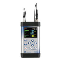
Svantek SVAN 958A User Manual (306 pages)
FOUR CHANNELS SOUND & VIBRATION LEVEL METER & ANALYSER
Brand:
Svantek
| Category:
Measuring Instruments
| Size: 8 MB
Table of Contents
Table of Contents
3
Introduction
9
SVAN 958A as Sound Level Meter & Analyser
10
SVAN 958A as Vibration Meter & Analyser
10
General Features of SVAN 958A
11
Accessories Included
11
Accessories Available
11
Available Firmware
12
Firmware Options
12
General Information
13
Input and Output Sockets of the Instrument
13
Powering of the Instrument
15
Control Keys on the Front Panel
16
Working with the Instrument
19
Measurement Mode
19
Configuration Mode
20
Default Settings
23
Description of Icons
23
Memory Organisation
25
FUNCTIONS of the INSTRUMENT - Function
27
Measurement Functions of the Instrument - Measurement Function
27
Activation of Optional Functions
28
Instruments Calibration - Calibration
28
Calibration of the Instrument Channels - Channel X
28
Calibration by Setting Transducer's Sensitivity - by Sensitivity
29
Calibration by Measurement - by Measurement
29
History of the Calibrations - Calibration History
30
MEASUREMENT PARAMETERS SETTING - Input
32
Selection of Measurement Parameters - Measurement Setup
33
Setting Parameters for Channels - Channels Setup
35
Setting the Data Logging Functionality - Logger Setup
36
Setting Parameters of Auxiliary Functions - Auxiliary Setup
38
Setting the RPM Measurement - RPM Setup
38
Setting the Parameters of Attenuation Measurements - "SEAT" Setup
39
Settings for Vector Calculations - Vector Setup
39
Setting the Parameters for Dose Measurements - HAV/WBV Dose Setup
39
Triggering Mode and Parameters Selection - Trigger Setup
41
Measurement Trigger Setup - Measure Trigger
41
Logger Trigger Setup - Logger Trigger
42
Alarm Trigger Setting - Alarm Trigger
43
Alarm on SMS Trigger Setting - Alarm SMS Notification
44
Alarm on E-Mail Trigger Setting - Alarm E-Mail Notification
44
Definition of Triggering Conditions for Logger and Alarms - Trigger Events Setup
44
DATA AVAILABLE on the DISPLAY - Display
47
Selection of the Modes of Measurement Results Presentation - Display Modes
47
Setting the Parameters of Graphical Presentations - Display Setup
51
Checking the Instrument Powering - Power Supply
52
Setting the Display Brightness and Power Saver - Screen Setup
52
Checking the Modem Status - Modem Status
53
Checking the Specification of the Instrument - Unit Label
53
SAVING the MEASUREMENT RESULTS - File
54
Saving Files in the Instruments Memory or External Memory
55
Controlling Data Storing in the Instruments Memory - Save Options
56
Loading Files with the Measurement Results - Load File
58
Checking the Contents of the Loaded File - Logger View
58
Removing File with the Measurement Results - Delete
59
Removing All Files with Measurement Results from Memory - Delete All
59
Merging Result and Setup Files Memory - Defragmentation
60
Checking the Contents of the Memory - Catalogue
60
Checking the Free Space in the Memory - Free Space
60
Saving Setup in the Instruments Memory - Save Setup
61
Options for Setup Files - Setup Options
61
Loading the Files with the Configuration - Load Setup
61
Checking the Contents of the USB Memory Disk - USB Directory
61
ADDITIONAL SETTINGS - Setup
63
Setting the Language of the User Interface - Language
64
Return to the Factory Settings - Clear Setup
64
Automatic Measurement Start - Auto Start
64
Day Time Limits Selection - Day Time Limits
64
Selection of the Extended Mode - Ext. I/O Setup
65
Turning off Instrument Due to Low External Voltage - Ext. Power Setup
66
Programming Keyboard - Keyboard Setup
66
Locking the Menu - Menu Lock
67
Reference Signal in Vibration Measurements - Reference Levels
67
Activating the Remote Control Error Confirmation - Remote Control Setup
67
Selection of Detector's Type in the LEQ (RMS) Calculations - RMS Integration
67
Setting the Parameters of the Serial Interface - RS232 Setup
68
Programming the Instrument's Internal Real Time Clock - RTC
68
Selection of Statistics Levels to be Saved in a File - Statistical Levels
69
Programming the Instruments Internal Timer - Timer
69
Programming the Instruments Socket Named Usb Host - Usb Host Setup
70
Setting User Filter Coefficients for 1/1 Octave and 1/3 Octave Analysis - User Filters
71
Selection of the Vibration Units - Vibration Units
71
Warnings Selection - Warnings
72
Parameters of Remote Communication - Wireless Communication
72
Selection of the Network Type - Network Setup
73
Configuration of Modem Basic Settings - Modem Setup
73
Setting of Support Modem Options - Modem Connection
74
Configuration of SMS Service - SMS Option
75
Configuration of E-Mail Service - E-Mail Settings
75
CALCULATION of DOSE PARAMETERS - Auxiliary Functions
77
Calculation of Hand-Arm or Whole-Body Vibration Dose
77
PRINTING REPORTS - Report
79
Edit the User Title of the Report - Title
80
Printing the Measurement Results - Print Results
80
Selection the Printing Options - Print Options
81
10 1/1 and 1/3 Octave Analyser
82
Selecting 1/1 Octave or 1/3 Octave Analysis Function
82
Configuring 1/1- or 1/3-Octave Analyser
82
Selection of 1/1 Octave and 1/3 Octave Bandpass Results as Triggering Source
83
Display Options in 1/1 Octave and 1/3 Octave Analysis Mode
85
Presentation of 1/1 Octave and 1/3 Octave Analysis Results
85
Setting the Scale of the Spectrum Results Presentation - Display Scale
86
Setting Parameters of the Spectrum Presentation - Spectrum View
87
Setting Parameters for Total Values - Total Values
87
Setting User Filter Coefficients for 1/1 and 1/3 Octave - User Filters Setup
88
Dosimeter
90
Selecting Dosimeter Function
90
Selecting Dosimeter Parameters - Dosimeter Setup
90
Fft Analyser
92
Selecting FFT Analysis Mode
92
Selecting FFT Analysis Parameters - FFT Setup
92
Display Options in FFT Analysis Mode
94
Presentation of FFT Analysis Results
94
Setting the Scale of the Spectrum Results Presentation - Display Scale
95
Setting Parameters of the Spectrum Presentation - Spectrum View
95
Cross-Spectrum
96
Selecting Cross Spectrum Function
96
Selecting Channels for Cross-Spectrum Analysis - Cross Spectrum Setup
96
Sound Intensity
98
Selection of Sound Intensity Function
98
Selection of Parameters for Sound Intensity Analysis - Intensity Setup
98
Reverberation Time
99
Selecting RT60 Function
99
Setting RT 60 Parameters
99
Configuring Results View
102
Starting RT60 Measurement
102
Visualization of the RT 60 Measurements Results
103
Wave Recorder
106
Selecting Wave Recorder Function
106
Configuring Wave Recording Parameters - Wave Parameters
106
Appendix A. REMOTE CONTROL (V4.16.2)
107
Input / Output Transmission Types
107
Function #1 - Input / Output of the Control Setting Codes
107
Function #2 - Read-Out of the Measurement Results in the SLM or VLM Mode
109
Function #3 - Read-Out of the Measurement Results in 1/1 OCTAVE and 1/3 OCTAVE Mode
112
Function #4 - Read-Out of the Data File from the Internal Flash-Disc And/Or the Special File Located in the RAM Memory
113
Function #5 - Read-Out of the Statistical Analysis Results
115
Function #6 - Remote Setting of the User Filters
116
Function #7 - Special Control Functions
118
Function #9 - Writing Setup Files to the Internal Flash-Disc
122
Control Setting Codes
123
Appendix B. DATA FILE STRUCTURES (V4.16)
139
Structure of the SVAN 958A File
139
Structure of the Block with Meteorological Data
168
Structure of the File with the Results from Level Meter and Wave Recorder Modes
169
Structure of the File with 1/1 OCTAVE Analysis Results
170
Structure of the File with 1/3 OCTAVE Analysis Results
170
Structure of the File with FFT Analysis Results
171
Structure of the File Containing Lm Results from Loggers File
172
Structure of the File Containing 1/1 or 1/3 OCTAVE Analysis Results from Logger's File
172
Structure of the File Containing Fft Analysis Results from Loggers File
172
Structure of the File Containing Saved Instruments Setup
173
Structure of the File Containing Results from RT60 Function
173
Structure of the File Containing Averaged RT60 Measurement Results
173
Structure of the Logger File Containing Time-Domain Signal
174
Structure of the File with the Results of FFT Cross-Spectrum Analysis
174
Structure of the File with the Results of Sound Intensity Analysis
174
Contents of the File in the Logger
175
Record with the Results
175
Record with the State of the Markers
180
Record with the Breaks in the Results Registration
181
Record with the Breaks Account PAUSE in the Results Registration
181
Contents of the Files in the Logger Containing Time-Domain Signal
181
Samples Record
181
Date and Time
182
Appendix C. SVAN 958A TECHNICAL SPECIFICATIONS
183
Specification of SVAN 958A as Sound Level Meter (SLM)
183
Specification of SVAN 958A as SLM in the Standard Configuration
183
Effect of Vibration
192
Effect of the SA 277C Outdoor Microphone Kit (Channel 4 Only)
193
Effect of the SA 277D Outdoor Microphone Kit (Channel 4 Only)
193
Specification of SVAN 958A as Vibration Level Meter (VLM)
194
Specification of SVAN 958A as 1/1, 1/3 Octave and FFT Analyser
202
Configuration for Sound Inputs
202
Specification of SVAN 958A as 1/1, 1/3 Octave and FFT Analyser in the Standard
205
Configuration for Vibration Inputs
205
1/1 and 1/3 Octave Filters Characteristics
206
Digital HP Filter Implemented in 1/1 & 1/3 OCTAVE and FFT Analysis
209
FFT Analysis Specification
209
Frequency Characteristics of Implemented Broadband Digital Filters
213
Digital Weighting Filters Dedicated for Sound Input
213
Digital Weighting Filters Dedicated for Vibration Inputs
215
Miscellaneous Specification of SVAN 958A
224
Specification of the Accelerometers
231
Using the SA 277C Outdoor Microphone Kit (Channel 4)
236
Using the SA 277D Outdoor Microphone Kit (Channel 4)
261
Appendix D. DEFINITIONS and FORMULAE of MEASURED VALUES
291
Sound Level Meter
291
Basic Terms and Definitions (SLM Mode)
291
Definitions and Formulas of the Results (SLM Mode)
292
Definitions and Formulas of the Additional Dosimeter Function Results
295
Vibration Level Meter
296
Basic Terms and Definitions (VLM Mode)
296
Definitions and Formulas of the Results (VLM Mode)
297
Definitions of the Hand-Arm Vibration Results Available in the Vibration Mode
297
Definitions of the Whole-Body Vibration Results Available in the Vibration Mode
298
Statistical Levels - LN% Definition
299
Appendix E. Reverberation Time Calculations
301
Introduction
301
RT 60 Reverberation Time Definition and Calculation
302
Description of the Decay Curve Recording in Different Measurement Methods
304
Advertisement
Advertisement
Related Products
Svantek SVAN 977W
Svantek SVAN 977A
Svantek Shawcity SVAN 977C
Svantek 971A
Svantek SVAN 958
Svantek SVAN 979
Svantek SVAN 971
Svantek SVAN 974
Svantek SVAN 106
Svantek SVAN 948
Svantek Categories
Measuring Instruments
Test Equipment
Microphone system
Hearing Aid
Touch terminals
More Svantek Manuals
Login
Sign In
OR
Sign in with Facebook
Sign in with Google
Upload manual
Upload from disk
Upload from URL