
Subscribe to Our Youtube Channel
Related Manuals for Svantek SVAN 979


Summary of Contents for Svantek SVAN 979
- Page 1 USER MANUAL SVAN 979 SOUND & VIBRATION ANALYSER Warsaw, 2021-05-28 Copyright © 2021 SVANTEK. Rev. 2.01 All rights reserved.
- Page 2 Information in this document is subject to change without notice and does not represent a commitment on the part of Svantek. Svantek provides this document “as is”, without warranty of any kind, either expressed or implied, including, but not limited to, its particular purpose. Svantek reserves the right to make improvements and/or changes to this manual, or to the products and/or the programs described in this manual, at any time.
-
Page 3: Table Of Contents
SVAN 979 User Manual CONTENTS INDEX ..................................8 INTRODUCTION ............................12 SVAN 979 & A ....................13 OUND EVEL ETER NALYSER SVAN 979 & A .................... 13 IBRATION EVEL ETER NALYSER SVAN 979 ........................13 ENERAL FEATURES OF ............................ 14 CCESSORIES INCLUDED ............................ - Page 4 SVAN 979 User Manual 4.12 – A ......................61 DVANCED ALARM FUNCTION LARMS CONFIGURING DATA VIEWING – DISPLAY ....................62 – D ..................62 CTIVATION OF THE DISPLAY MODES ISPLAY ODES 5.1.1 Running SPL view ..........................63 5.1.2 One Result view ........................... 63 5.1.3...
- Page 5 SVAN 979 User Manual AUXILIARY SETTINGS – AUXILIARY SETUP ....................92 – L ..................92 ELECTING THE USER INTERFACE LANGUAGE ANGUAGE – F ..................92 ESTORING THE FACTORY SETTINGS ACTORY ETTINGS – R ..................... 93 ETTING THE REFERENCE LEVELS EFERENCE EVELS –...
- Page 6 SVAN 979 User Manual 14.4 STIPA ....................128 MEASUREMENT AND CALCULATION PROCESS 14.4.1 Measured results..........................128 14.4.2 Project structure..........................130 14.4.3 Averaging results ..........................131 14.4.4 STIPA settings ............................ 131 14.4.5 Considering ambient noise distortions ....................133 14.4.6 STIPA measurements ........................134 14.5...
- Page 7 OUND EVEL ETER C.1.1 Specification of SVAN 979 as SLM in the standard configuration ............258 C.1.2 Effect of the SA 22 windscreen......................... 282 C.1.3 Effect of the extension cable SC 93 ......................284 C.1.4 Effect of the SA 279 Outdoor Protection Unit ..................291 C.2.
-
Page 8: Index
SVAN 979 User Manual INDEX Copying file · 75 1/12-octave · 34, 100 1/1-octave · 34, 100 Data port · 88 1/3-octave · 34, 100 Data protocol · 87 1/6-octave · 34, 100 Data transfer · 87 Day time limits · 45 Decay ·... - Page 9 SVAN 979 User Manual Loudness · 34, 125 Low range · 58 General settings · 43, 101, 111 GPRS · 86 GPS · 79, 80 GPS view · 68 Main menu · 22 Gradient · 47 Maintenance · 142 Gradient trigger · 47 Manual file saving ·...
- Page 10 SVAN 979 User Manual Spectrum · 57, 101, 104, 113 Spectrum based user filters · 109 Spectrum statistics · 51 Range · 58, 101, 111 Spectrum table · 105 Real-time clock · 85 Spectrum type · 107, 108, 116 Real-time user filters · 93 Spectrum view ·...
- Page 11 SVAN 979 User Manual Wave format · 54 Windscreen compensation · 57 Wave recording · 54 Wireless transfer · 86 Wave trigger · 54 Working directory · 74...
-
Page 12: Introduction
(audio recording). A fast USB 1.1 interface (12 MHz) creates a real time link for the PC "front-end" application using the SVAN 979. The USB Host functionality is also available. The USB Host controller installed in the instrument enables the user to connect this meter to USB memory sticks, USB hard disks, USB printers etc. -
Page 13: Svan 979 As Sound Level Meter & Analyser
Class 1 IEC 61260-1: 2014. • Optional RPM measurement with the use of RPM probe, connected to the I/O socket of SVAN 979. • FFT analysis with the single Total overall value, performed with preselected frequency weighting filters and screens. -
Page 14: Accessories Included
GPS module with USB HOST plug 1.6 F IRMWARE OPTIONS AVAILABLE The standard firmware of SVAN 979 includes 1/1 and 1/3 octave analysis, FFT analysis, RT60, Time Domain Signal recording and STIPA. Other functions are optional: • SV 979_7 Loudness analysis option for SVAN 979 •... -
Page 15: General Information
SVAN 979 User Manual GENERAL INFORMATION 2.1 M EASUREMENT CONFIGURATIONS AS The instrument's normal operating mode as SLM assumes operating with a preamplifier and a microphone attached to the instrument and without a windscreen. Optionally the instrument can be operated with the windscreen attached to the microphone or with the preamplifier and microphone fitted in the outdoor microphone kit and connected with the instrument by the extension cable (see Appendix C.7 for specification). -
Page 16: Measurement Configurations As Vlm
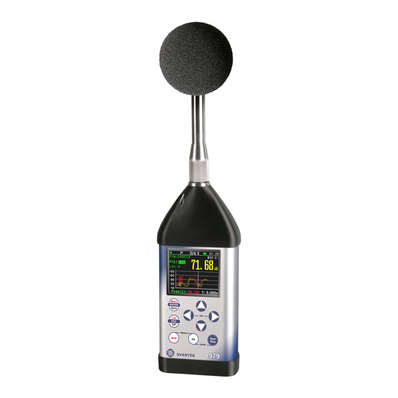
2.3 I NPUT AND OUTPUT SOCKETS OF THE INSTRUMENT SVAN 979 is supplied disassembled, so the user should mount the GRAS 40AE microphone and SV 17 preamplifier on his own. It doesn’t matter which elements will be assembled first: the microphone with the preamplifier or the instrument with the preamplifier. - Page 17 Note: The originally supplied Kingston Industrial memory card has been tested by SVANTEK and cards of this type are strongly recommended for use when the original card is going to be replaced.
-
Page 18: Control Keys On The Front Panel
SVAN 979 User Manual 2.4 C ONTROL KEYS ON THE FRONT PANEL Control of the instrument has been developed in a fully interactive manner. Convenient and intuitive menu is used for device configuration Thanks to that, the number of keys has been reduced to nine for ease of use and convenience. - Page 19 SVAN 979 User Manual • select a parameter value in an active position (e.g. filter Z, A, B etc., Start Delay period: 1s, 2s, 3s, … etc.); • control a cursor in the Spectrum, Logger and Statistics mode of result presentation;...
-
Page 20: Working With The Instrument
SVAN 979 User Manual An example below presents markers on the time history plot. Marker 1 Marker 2 Marker 3 Marker 4 13:30:00 13:30:09 13:30:17 13:30:26 13:30:35 13:30:43 13:30:52 Note: When the screen saver function is active (see Chapter 5.4) you may face the problem that during dimmed or switched off screen you should press the ▲, ◄, ►... -
Page 21: Measurement Mode
SVAN 979 User Manual Measurement mode 2.5.1 The measurement results can be viewed in different view modes, the set of which depend on the selected Measurement Function and which you can change and activate/deactivate. Measurement results viewing Measurement results can be presented in different views, so called display modes, some of which are always available, and some can be activated or deactivated. -
Page 22: Configuration Mode
SVAN 979 User Manual Pausing measurement To pause a measurement, press the <S/P> key (<Alt>+<ESC>). The measurement will be paused and the icon will appear together with the Pause section at the bottom of the screen. <S/Pt> The Pause mode allows you to erase up to 16 last seconds of the measurement with the ◄... - Page 23 SVAN 979 User Manual List of parameters The list of parameters contains parameters the value of which is selected from the available range or set. • The desired position in a list is accessed with the ▲ / ▼ key.
-
Page 24: Instrument Power
2.6 I NSTRUMENT POWER SVAN 979 can be powered by one of the following sources: • Four AA standard size internal batteries. In case of alkaline type, a new fully charged set can operate more than 12 h (6.0 V / 1.6 Ah). Instead of the ordinary, four AA rechargeable batteries can be used (a separate external charger is required for charging them). -
Page 25: Default Settings
SVAN 979 User Manual When there is a connection to the USB interface (USB Device socket is connected by the cable to a PC), the „USB”icon is presented on the top of the display and in the Battery screen there is the message: USB Power Voltage: x.xxV. -
Page 26: Description Of Icons
SVAN 979 User Manual Profile 3 weighting filter (Filter(3)=Z), Fast detector (Detector(3)=Fast). Default profiles settings for Vibration measurements: Profile 1 - HP1 weighting filter (Filter(1)=HP1); 1.0s RMS detector (Detector(1)=1.0s); Profile 2 - HP3 weighting filter (Filter(2)=HP3), 1.0s RMS detector (Detector(2)=1.0s);... -
Page 27: Saving Data
All available measurement results and settings can be stored in the memory (micro SD Card or USB Disk) as files in the predefined or assigned directories. The measurement files are stored by default in the predefined SVANTEK directory. The setup files are stored in the predefined directory SETUP. Other special files (logs,... - Page 28 SVAN 979 User Manual advanced alarms settings) are stored in the predefined SYSTEM directory. The predefined directories can be reassigned or renamed by the user. The SD Card memory is activated automatically after insertion of the card. The manual activation of the USB Disk is needed.
- Page 29 DD is a day of the first measurement. ◄ The measurement day directories are created in the working directory, which can be of predefined SVANTEK name or can be created by the user with the user name. The working directory is displayed in the bottom line of the File Manager screen together with the memory icon.
- Page 30 SVAN 979 User Manual The screens below show the automatic file saving during two subsequent measurements. Before and during the first measurement the file name L30 is displayed. This file is saved automatically in the directory hh-mm- ss after the measurement stop. After start of the second measurement the instrument automatically changes the file name to L31 and this file will be saved after of the second measurement stop and so on.
- Page 31 SVAN 979 User Manual File with the proposed or created by you name will be saved in the working directory on the SD card or the USB disk. There may be a naming conflict in the working directory. this case, instrument will save the file under the proposed name.
-
Page 32: Files Downloading And Uploading
SVAN 979 User Manual Note: The wave files usually are big in size and may use enormous memory space. Since the wave- file name is not displayed on the result view screen, you should remember that wave recording function is active and switch it off always when wave recording is not required. - Page 33 SVAN 979 User Manual Pressing simultaneously <Shift> and ◄ keys right after turning on the instrument allows you to check and lock back early unlocked options. For example, if you wish to lock the 1/1 Octave function, deselect it and press <ENTER>.
-
Page 34: Functions Of The Instrument - Function
The Mode relates to the type of transducer connected to the instrument: microphone with preamplifier or accelerometer. Sound Meter and Vibration Meter modes relates to the Svantek standard accessories, while Direct Sound and Direct Vibration modes enable using of other manufactures’ transducers. -
Page 35: Instrument
SVAN 979 User Manual Note: The type of measurement function and the measurement mode is displayed in the upper line of the screen in the form of abbreviation as presented below: - SLM Sound Level Meter, - VLM Vibration Level Meter,... -
Page 36: System Check
SVAN 979 User Manual Note: The calibration factor is always added to measurement results and measurement range limits of the Level Meter, 1/1 Octave, 1/3 Octave and other functions. Note: The calibration level and the calibration result are expressed in different units depending on the settings of the instrument. -
Page 37: Calibration By Sensitivity (Vibration Signal)
SVAN 979 User Manual 2. Set the Sensitivity of the microphone taken from its calibration certificate using the ◄ / ► key and then press <ENTER>. The calibration factor (Cal. Factor) is calculated every time after pressing the ◄ / ► key, in relation to the nominal value of 50.00 mV/Pa. -
Page 38: Calibration By Measurement (Vibration Signal)
SVAN 979 User Manual 2. Set the reference calibration level (Cal. Level) – see Appendix C, Chapter C.1, par. Calibration. 3. Attach the acoustic calibrator SV 36 (or equivalent 114 dB@1000 Hz) carefully over the microphone of the instrument. Note: It is also possible to use an electro-mechanical pistonphone, which generates a signal (ca 124 dB) or different type of acoustic calibrator dedicated for ½”... -
Page 39: History Of Performed Calibrations - Last Calibration
SVAN 979 User Manual Set the calibration level (Cal. Level) appropriate to the used calibrator. The default level for calibration in the vibration mode is 10 m/s at 159.2 Hz. Remember to change this level if using an alternative vibration calibration signal source. -
Page 40: Erasing Calibration Records - Clear Calibr. History
SVAN 979 User Manual The calibration record screen contains the information regarding performed calibration: date and time, used calibration method, obtained calibration factor. <ENT> Erasing calibration records – Clear Calibr. History 3.3.7 You can erase all calibration records. To do... - Page 41 SVAN 979 User Manual After calibration measurement stop, the Calibration Result (the measured reference signal without calibration factor correction) New Calibration Factor (difference between the Calibration Level and the Calibration Result, calculated in dB) are displayed. 3. Press <ENTER> to save the new calibration factor (Enter to Confirm), press <ESC>...
-
Page 42: Configuring Measurement Parameters - Measurement
SVAN 979 User Manual CONFIGURING MEASUREMENT PARAMETERS – Measurement The Measurement section groups items of the menu related to configuration of measurement parameters. The content of the Measurement list depends settings Mode Measurement Function. <ENT> The Measurement list contains the following positions: General Settings allowing you to set up general measurement parameters;... -
Page 43: Setting Up General Measurement Parameters - General Settings
SVAN 979 User Manual – G 4.1 S ETTING UP GENERAL MEASUREMENT PARAMETERS ENERAL ETTINGS The General Settings list allows you to set general measurement parameters: measurement start delay (Start Delay), maximum delay period synchronization with RTC (Start Sync.), measurement period (Integration Period),... - Page 44 SVAN 979 User Manual During the Integration Period, the instrument performs series of 1-second measurements/integrations, and every second averages 1-second results with the results averaged for n-1 seconds. These averaged results are displayed and renewed every second for the elapsed measurement time (n seconds). In the end of the Integration Period the averaged measurement results are saved in the logger file providing that such saving is enabled.
-
Page 45: Setting Measurement Trigger - Measurement Trigger
SVAN 979 User Manual Selecting Lin is required for obtaining the true RMS value of the measured signal according to IEC 61672- 1:2013. When this option is selected the value of the Leq, SEL, LEPd and L(den) results do not depend on the detector time constant: Fast, Slow or Impulse (the results are displayed without the indicator of the detectors selected in the profiles). - Page 46 SVAN 979 User Manual Slope trigger The Slope + / Slope - trigger starts the measurement/integration with the duration of the Integration Period on condition: rising value of the measured result (Source) averaged by 0.5 ms passes above/below the threshold value (Level).
-
Page 47: Setting Parameters For Profiles - Profiles
SVAN 979 User Manual Gradient trigger The Grad + trigger starts the 1-second measurement/integration on condition: value of the measured result (Source) averaged by 0.5 ms is greater than the threshold value (Level) and the gradient of this Source is greater than the gradient threshold value (Gradient). -
Page 48: Data Logging - Logging
Auxiliary Setup / User Filters / Real Time Filters). The characteristics of these filters are given in Appendix C. Note: The Real Time Filters for SVAN 979 is an extra cost option, part number SV 979_16. RMS detector Available RMS detectors (time constants):... -
Page 49: Setting Logger General Parameters - Logger Setup
SVAN 979 User Manual Note: LXY is an abbreviation for the L (or Spl) result measured with X filter and Y detector time constant – see Appendix D. Summary results are saved in the same file with logger results. Blocks of summary results are recorded in the file in the end of every measurement cycle. - Page 50 SVAN 979 User Manual Summary Results saving The Summary Results position enables saving of summary results for each measurement cycle including results obtained from the weather station (Meteo results), statistics and spectra. Default value: enabled. Logger step Logger Step defines a period of the logger results measuring and logging in a file.
-
Page 51: Selecting Results For Logging - Logger Results
SVAN 979 User Manual Selecting results for logging – Logger Results 4.4.2 In the Logger Results list you can select results for three independent profiles (Peak, Max, Min, Leq, LXY, LR1 and LR2 for Sound measurements and Peak, P-P, Max... - Page 52 SVAN 979 User Manual Level trigger The Level + / Level - trigger enables logging of the Logger results with the Logger Step on condition: value of the measured result (Source) averaged over the Logger Step period is greater/lower than the threshold value (Level). In other cases, the logging is skipped.
-
Page 53: Setting Markers - Marker Setup
SVAN 979 User Manual The period during which the logger results are saved before or after the fulfilment of the trigger condition can be calculated by multiplying the value set up in the Pre or Post positions by the value set up in the Logger Step position (path: <Menu>... -
Page 54: Configuring Signal Recording - Wave Recording
SVAN 979 User Manual Configuring signal recording – Wave Recording 4.4.6 Wave Recording position allows activating and setting parameters of a waveform signal recording in the separate file with the extension WAV. WAV files are saved automatically same measurement directory as logger files (hh- mm-ss). - Page 55 SVAN 979 User Manual Slope trigger The Slope+ / Slope- trigger starts a signal recording on condition: rising/falling value of the measured result (Source) averaged over the Trigger Period passes above/below the threshold value (Level). After pressing the <Start> key the instrument checks the trigger condition with steps, defined by the Trigger Period parameter, and if condition is met starts the signal recording.
- Page 56 SVAN 979 User Manual External type trigger When External is selected, recording starts from the external signal on the I/O socket. In this case, it is necessary to set up the I/O Mode parameter as Digital In (path: <Menu> / Instrument / Multifunction I/O).
-
Page 57: Setting Spectra - Spectrum
) compensations are dedicated for the permanent outdoor monitoring applications with the use of the SA 279 outdoor microphone outdoor kit (usually when SVAN 979 is working as a part of the SV 279 monitoring station). The characteristics of the outdoor filters depend on the dominating sound incidence angle: environmental monitoring (incidence angle 90 deg) or airport monitoring (incidence angle 0 deg). -
Page 58: Selecting Measurement Range - Range
SVAN 979 User Manual – R 4.7 S ELECTING MEASUREMENT RANGE ANGE The Range position is used for setting the measurement range of the instrument. The Range screen presents for the selected range: Leq linearity range, Leq dynamic range and Peak range for 1 kHz. -
Page 59: Setting Rpm Measurement - Rpm Measurement
SVAN 979 User Manual The default statistical levels have following settings: 10, 20, 30, 40, 50, 60, 70, 80, 90 and 95. All values should be within the integer range [1, 99]. Each individual value can be set independently from others. -
Page 60: Example Of Timer Execution
SVAN 979 User Manual Time of measurement start The Start Hour position determines the time for the measurement to start. The required hour and minute can be selected in a special screen, which is opened with the ◄ / ► key. -
Page 61: Advanced Alarm Function - Alarms
SVAN 979 User Manual It is recommended to set the Start Delay time to 0 seconds for the Timer function. – A 4.12 A DVANCED ALARM FUNCTION LARMS Alarms position appears Measurement list if the advanced alarms configuration file (ALARM.SVA) is uploaded to the predefined SYSTEM catalogue. -
Page 62: Configuring Data Viewing - Display
SVAN 979 User Manual CONFIGURING DATA VIEWING – Display The Display section contains elements for programming presentation of measurement result and display parameters. The content of the Display list depends on the selected measurement function. <ENT> The Display section contains following items: Display Modes allowing you to define active modes of a measurement results presentation;... -
Page 63: Running Spl View
SVAN 979 User Manual Changing display modes Being in the measurement mode you can change the view mode with the ▲ / ▼ key pressed together with <Alt>. Running SPL view 5.1.1 The Running SPL view is available in the Sound measurement modes. It shows in a large format one measured result –... -
Page 64: Combined Views
SVAN 979 User Manual 8. Elapsed time, showing the current second of the measurement. The value presented here belongs to the range [0, Integration Period]. Note: Detector type for the displayed result depends on settings in General Settings and Profiles lists (path: <Menu>... - Page 65 SVAN 979 User Manual 5. Value of the measured result. 6. Units of the measured value. 7. Elapsed time, showing the current second of the measurement. The value presented here belongs to the range [1, Integration Period]. 8. File name when Logger is enabled (path: <Menu>...
-
Page 66: Logger View
SVAN 979 User Manual Changing the active fields You can change the active field with the ▲ / ▼ (vertically) or ◄ / ► (horizontally) key. ▼ Logger view 5.1.4 The Logger view depends on the settings made in the Logging list (path: <Menu> / Measurement / Logging). -
Page 67: Spectrum View
SVAN 979 User Manual To display a different result, it is necessary to move to field 3 with the ▲/▼ button, and then select the appropriate result with the ◄/► button pressed together with <Alt>. ► <Alt>+ Spectrum view 5.1.5... -
Page 68: File Information View
SVAN 979 User Manual The cursor position is changing with the ◄ / ► key. The statistical level and appropriate value are presented in the line below the plot. ►… File information view 5.1.7 The File Info position enables the additional file information view. -
Page 69: Signal Generator View
SVAN 979 User Manual Signal Generator view 5.1.11 The Signal Generator view allows you to control the signal generator function of the instrument. This position is active only when the Signal Generator function is switched on (Active) in the Instrument menu (path: <Menu>... -
Page 70: Adjusting Plot Views - Display Scale
SVAN 979 User Manual – D 5.2 A DJUSTING PLOT VIEWS ISPLAY CALE The Display Scale list of parameters allows you to define the result units (absolute or logarithmic), number of digits after decimal point, adjust scale of plots, toggle a grid and automatic scale adjustment. -
Page 71: Adjusting Logger View - Logger View
SVAN 979 User Manual Toggling the grid The Grid position allows you to switch on or off the horizontal grid lines of the logger or spectrum plot. => Toggling automatic Y-scale adjustment Autoscale position toggles automatic adjustment Y-axis dynamics to the measured result level. The... -
Page 72: Setting The Colour Theme Of The Display - Themes
SVAN 979 User Manual Power saver function The saving of the internal source of the instrument’s power can be achieved by reducing the brightness of the screen when possible. There are two options for the power saver function. The screen may be switched off (Screen off on idle) and/or dimmed (Dim screen on idle). -
Page 73: Managing Files - File
SVAN 979 User Manual MANAGING FILES – File The File section contains the elements that enable managing data (logger and wave) and setup files saved in the instrument’s memory (micro SD card). The memory structure and files saving methods are described in Chapter 2.9. -
Page 74: Assigning Directory For Data Files Saving - Set As Working Dir
SVAN 979 User Manual In the File Manager screen, you can check the memory content, create new directories and files, select directory for automatic data files saving, rename and delete files and directories. All these operations can be done on the selected file or directory by means of the <ENT>... -
Page 75: Copying Files/Directories - Copy
SVAN 979 User Manual Opening the logger file means that the measurement results saved in this file will be loaded instrument's operation memory and may be reviewed on the screen. The results are loaded together with the Mode and Measurement Function settings, but other measurement settings are as before opening the logger file. -
Page 76: Renaming Files/Directories - Rename
SVAN 979 User Manual Renaming files/directories – Rename 6.1.5 You can rename files or directories. To do this, select the desired file or directory and press <ENTER>. Select the Rename position in the command list and press <ENTER>. The special screen with editor function will be opened. -
Page 77: Erasing All Files In A Memory - Delete All
SVAN 979 User Manual Erasing all files in a memory – Delete All 6.1.8 You can delete all elements from the memory. To do this, select the desired memory (SD Card or USB Disk) and press <ENTER>. Select the Delete All position in the command list and press <ENTER>. -
Page 78: Configuring Instrument Parameters - Instrument
SVAN 979 User Manual CONFIGURING INSTRUMENT PARAMETERS – Instrument The Instrument section is used for setting the various parameters which are primarily dedicated for controlling of the instrument hardware. <ENT> The Instrument list contains following positions: Auto Start allowing you to automatically start the measurement just after turning the instrument on;... -
Page 79: Checking Power - Battery
The USB Host socket can be used as the input of the different interfaces: RS 232 or USB. The RS 232 interface in SVAN 979 is available as a hardware option (a special SV 55 interface/converter with dedicated microprocessor has to be attached to the USB Host socket). -
Page 80: Setting External Power O N /Off Conditions - External Power
SVAN 979 User Manual The USB disk should be disconnected when the measurements are not performed or working directory was set up at the SD card. In the USB disk, that is divided into partitions its first partition must be reserved for FAT32 or FAT16 file system. -
Page 81: Selecting Iepe Current Supply - Iepe Current
SVAN 979 User Manual – IEPE C 7.7 S IEPE ELECTING CURRENT SUPPLY URRENT The IEPE Current position allows you to disable IEPE (IEPE Off) or to choose the correct IEPE supply current for the used microphone accelerometer Direct Sound mode: IEPE Current 1.5 mA or IEPE Current 4.5 mA. -
Page 82: Checking The Modem Status - Modem Status
SVAN 979 User Manual – M 7.9 C HECKING THE MODEM STATUS ODEM TATUS The Modem Status position is active only when the GPRS option is selected (path: <Menu> / Instrument / Wireless Transfer / Network). This screen shows status of the 3G connection when SV 979 works as a part of the SV 279 PRO/PRIM monitoring station. - Page 83 SVAN 979 User Manual When D/A is selected, the analogue signal from the internal signal generator of the instrument after digital-to-analogue converter is transmitted to the pin 1 of the I/O connector, and the analogue input signal is transmitted to the pin 2 of the I/O connector after digital-to-analogue converter.
-
Page 84: Setting Microphone Polarisation Voltage - Polarisation Voltage
SVAN 979 User Manual Alarm trigger threshold level The Alarm Level parameter defines the threshold level for triggering an alarm pulse generation. If the Source value is greater than the Alarm Level, the instrument will generate the alarm signal with the selected logic. The available levels are within the range [30.0 dB, 140 dB] in Sound modes and [60.0 dB,... -
Page 85: Setting Parameters Of The Serial Interface - Rs232
SVAN 979 User Manual – RS232 7.13 S ETTING PARAMETERS OF THE SERIAL INTERFACE The RS232 position becomes active after activation RS232 Communication Ports screen and enables programming RS 232 interface transmission speed (Baud Rate) and the time limit during which the communication operation should be performed (Time Out). -
Page 86: Selecting Network Type - Network
IRELESS RANSFER SVAN 979 is not equipped with the modem and itself cannot assure data transfer via mobile network. However, it can control data transfer via the modem that supports GSM connection with the help of the Wireless Transfer functionality. The connection with the external modem is carried out via the USB port. -
Page 87: Configuring Data Transfer - Data Transfer
TCP S the values are: Off, On (registration using Connection Request Packets), AS (periodic registration on Svantek Server Address), SMT.AS (registration on Svantek Server Address – performed each time internet connection is initialized by the modem); in case of UDP, the values... -
Page 88: Configuring Connections - Modem Connection
SVAN 979 User Manual • Sim Auth Mode – defines the method of user verification by a SIM card type. Depending on the SIM card, several options are possible, some of them are recognized by the modem: • none – no verification required. -
Page 89: Configuring Sms Service - Sms Options
SVAN 979 User Manual • APN – allows you to enter up to 20 characters of APN name of the SIM card used with the modem. • APN User – allows you to enter up to 20 characters of user name used for verification by the SIM card used with the modem. -
Page 90: Configuring E-Mail Service - E-Mail Settings
SVAN 979 User Manual Configuring e-mail service – E-mail Settings 7.17.6 The E-mail Settings position allows you to configure the e-mail service used for alarm notification. If the SvanMail position is enabled, you should define only positions: Recipient e-mail, E-mail Subject and E-mail Message. The SvanMail option allows instruments, compatible with SvanNET, send e-mails without additional parameters, simplifying the process of configuring alarm notifications. -
Page 91: Data Transfer With Modbus Protocol - Modbus
▲ / ▼ key. <ENT> Note: The contents of the Unit Label screen should be always sent to the Svantek service department or official representative in case of any problems faced by the user during the instrument’s normal operation. -
Page 92: Auxiliary Settings - Auxiliary Setup
SVAN 979 User Manual AUXILIARY SETTINGS – Auxiliary Setup Auxiliary Setup section provides additional functions that allow, for instance, customization of the device interface to a specific user requirement and are not directly related to the hardware components of the instrument. -
Page 93: Setting The Reference Levels - Reference Levels
SVAN 979 User Manual – R 8.3 S ETTING THE REFERENCE LEVELS EFERENCE EVELS The Reference Levels position allows you to set reference levels for the measured acceleration (Acc), velocity (Vel) and displacement (Dil) results. For sound measurements it only informs about the default reference sound level. -
Page 94: Selecting Units For Vibration Results - Vibration Units
SVAN 979 User Manual In the Rx (R1, R2, R3) screen you can select the filter Type (Highpass, Bandpass or Lowpass) and define frequency corners: low frequency corner - LFC(3dB) and high frequency corner - HFC(3dB). Bandpass filters require definition of two frequencies: LFC(3dB) and HFC(3dB). - Page 95 SVAN 979 User Manual Checking free space of the memory If the Ext. Disk Free Space warning is enabled the instrument will verify free space on the SD-card and will generate the warning when the space is lower than Min Free Space.
- Page 96 SVAN 979 User Manual Low Battery warning If the Low Battery warning is enabled, the instrument will display the message in the case the internal battery capacity drops below 10%. Warning “Low Battery” will be displayed shortly every 20 seconds.
-
Page 97: Reports Printing - Report
SVAN 979 User Manual REPORTS PRINTING – Report The Report section allows you to print reports Sound Vibration measurement results in the predefined format on the printers directly connected to the SVAN 979 instrument. <ENT> The Instrument list contains the following positions: Print Results allowing you to print out the measurement results;... -
Page 98: Printing Measurement Results - Print Results
SVAN 979 User Manual Note: All reports are printed in the character format using the ASCII set on either A4 or A5 size paper. – P 9.1 P RINTING MEASUREMENT RESULTS RINT ESULTS The Print Results position allows you to print the report on the attached printer. -
Page 99: Printing User Filters Coefficients - Print User Filters
SVAN 979 User Manual – P 9.3 P RINTING USER FILTERS COEFFICIENTS RINT ILTERS The Print User Filters position allows you to print out the values of the user filters: S1, S2, S3, S4 and S5. Select the required filter and press <ENTER>... -
Page 100: 10 1/1-Octave - 1/12-Octave Analyser
SVAN 979 User Manual 1/1-OCTAVE – 1/12-OCTAVE ANALYSER The instrument operates as a real time 1/1-octave - 1/12-octave analyser (RTA) in a very similar way to the level meter. Moreover, 1/1-octave - 1/12-octave analysis is performed in parallel with the level meter measurements. -
Page 101: General Settings For 1/1-Octave - 1/12-Octave Analysis - General Settings
SVAN 979 User Manual General settings for 1/1-octave – 1/12-octave analysis – General Settings 10.2.1 Averaging of results for each spectrum band is performed for the Integration Period and is repeated the Repetition Cycles times. 1/1-octave – 1/12-octave spectra are always saved as Summary Results. - Page 102 SVAN 979 User Manual Available bands for sound analysis are as follows: 1/1 Octave: Audio (31.5-16k) - 10 filters with centre frequencies from 31.5 Hz to 16 kHz => Full (1-16k) - 15 filters with centre frequencies from 1 Hz to 16 kHz =>...
- Page 103 SVAN 979 User Manual Full (0.73-21.8k) - 180 filters with centre frequencies from 0.73 Hz to 21.8 kHz => Available bands for vibration analysis are as follows: 1/1 Octave: Full (1-16k) - 15 filters with centre frequencies from 1 Hz to 16 kHz =>...
-
Page 104: Configuring 1/1 - 1/12 Octave Spectra Views
SVAN 979 User Manual RMS detector selection Detector parameter defines LEQ/RMS detector for the 1/1-octave - 1/12- octave analysis. For Sound measurements, it is possible to select the Linear, Fast or Slow detector. For Vibration measurements, only Linear detector is available. -
Page 105: Adjusting Scales Of The Spectrum Plot - Display Scale
SVAN 979 User Manual You can shift the Y-axis in the spectrum view with the <Shift> and ▲ / ▼ keys pressed together. ▼ <Sh/ > You can change the cursor position with the ◄ / ► key. You can jump to the first or last... -
Page 106: Selecting Spectra To Be Viewed - Spectrum View
SVAN 979 User Manual Resolution The Resolution parameter appears when Scale is Log and defines the number of digits after the decimal point in the presented results: one digit after the decimal point (0.1 dB) or two digits after the decimal point (0.01 dB). -
Page 107: Spectrum Statistics
SVAN 979 User Manual When the Averaged or Instantaneous spectrum is selected, you can additionally enable presentation of the Max and/or Min values for each band by switching the Max or Min parameters on. The Max and Min spectrum is presented as a stepped line –... -
Page 108: Changing Spectrum Type In Vibration Modes - Spectrum Type
SVAN 979 User Manual 3. Select the Lnn field in the Ln spectrum view with the ▲ / ▼ key. 4. Select the required Lnn result with the ◄ / ► key pressed together with <Alt>. ► <Alt>/ 5. Shift the cursor on the required band or the Total value with the ◄... -
Page 109: Setting Filter Coefficients For 1/1 Octave - 1/12 Octave Analysis - Spectrum Based Filter
SVAN 979 User Manual – S 10.4 S 1/1 O - 1/12 O ETTING FILTER COEFFICIENTS FOR CTAVE CTAVE ANALYSIS PECTRUM ASED ILTER The Spectrum Based Filter position (path: <Menu> / Auxiliary Setup / User Filters), allows you to set values of the filter... - Page 110 SVAN 979 User Manual In the Sx screen select the centre frequencies of the filters and their coefficients: • for 0.80 Hz in the range: -100.0dB ... 100.0dB • for 1.00 Hz in the range: -100.0dB ... 100.0dB • •...
-
Page 111: Fft Analyser
SVAN 979 User Manual FFT ANALYSER The instrument operates as the FFT analyser in a very similar way to the Level Meter. Moreover, the FFT analysis is performed in parallel with the SLM or VLM measurements. Results of the FFT analysis (spectra) measured with preselected frequency weighting filter and window, are presented in the Spectrum view. -
Page 112: Logging Of Fft Spectra - Logging
SVAN 979 User Manual Logging of FFT spectra – Logging 11.2.3 Spectra can be logged in a logger file with two steps: Integration Period step and/or Logger Step. For logging FFT spectra, the Logger position must be enabled in the Logger Setup screen (path: <Menu>... -
Page 113: Configuring Fft Spectra View
SVAN 979 User Manual You can easily get into the FFT screen from the spectrum view. It is necessary to enter the function field (FFT) with the ▲ / ▼ key and press <ENTER>. <ENT> 11.3 C ONFIGURING SPECTRA VIEW... -
Page 114: Setting Up The Scale Of Spectrum Plot - Display Scale
SVAN 979 User Manual You can change the cursor position with the ◄ / ► key. You can jump to the first or last spectrum line with <Shift>.and ◄ / ► keys pressed together. The frequency and appropriate value are presented in the line below the plot. -
Page 115: Selection Of Spectra To Be Viewed - Spectrum View
SVAN 979 User Manual It is possible to select the range from the set: 10dB, 20dB, 40dB, 80dB, 100dB and 120dB. => Toggling the grid The Grid position allows you to toggle the horizontal grid lines of the logger or spectrum plot. -
Page 116: Changing Spectrum Type In Vibration Modes - Spectrum Type
SVAN 979 User Manual Changing spectrum type in Vibration modes – Spectrum Type 11.3.4 In the Spectrum Type screen, which is available only in Vibration modes, you can select the different types of vibration spectra presented display: Acceleration, Velocity or Displacement. -
Page 117: Reverberation Time Measurements - Rt60
(A, C and Z weighted). Whole measurement process and calculations implemented in SVAN 979 fulfil the ISO 3382 standard. The reverberation time of the room can be obtained with the use of SVAN 979 by two measurement methods: Impulse Response Method (Impulse) and Interrupted Noise Method (Decay). The selection of the method depends on the type of the used sound source. - Page 118 SVAN 979 User Manual The Method parameter allows you to choose the method for RT60 calculations: Decay or Impulse. Both methods are described in Appendix E. ► The Octave parameter defines for which bands (1/1 or 1/3) the RT60 analysis will be performed.
-
Page 119: Configuring Rt60 Views
SVAN 979 User Manual Note: Although the instrument generates pink noise, the Signal Generator position of the Instrument section is unavailable in the RT60 function. The Noise Margin parameter defines the margin value to the calculated noise level (for more detail see Appendix E). This parameter can be set in the range 0.0 dB ÷... -
Page 120: Start Rt60 Measurements
SVAN 979 User Manual 12.4 S RT60 TART MEASUREMENTS Measurements with the use of Decay method Set parameters for Decay RT60 measurements. Most used setup is presented below. • Method: Decay • Recording Time: • Time Step: 10 ms • Smoothing: •... -
Page 121: Viewing Of Rt60 Results
SVAN 979 User Manual • Noise Mar.: 10.0 dB • Level: 100 dB Place the microphone in one of the selected measurement points (for the measurement points location see the reverberation time measurement ISO standard). Note: The default measurement time of the decay curve registering (Recording Time) is 7 seconds. - Page 122 SVAN 979 User Manual Bar plot of RT60 results 1. Number of averaged results 2. RT 1/3 octave plot 3. Name of the RT result and its value 4. Used RT60 calculation method 5. Cursor position 6. RT results for Total values 7.
- Page 123 SVAN 979 User Manual <ENT> <ENT> Sound pressure decay curve plot 1. Logger file content 2. T0 marker position 3. Decay curve plot 4. Central frequency of selected by cursor 1/3 octave band 5. Result value (SPL) for the cursor position 6.
- Page 124 SVAN 979 User Manual Changing the cursor position When the field 14 is active you may change the cursor position with the ◄ / ► key. ◄… RT User reverberation time calculation Select the band or one of the total levels for user reverberation time calculation process.
-
Page 125: Loudness Measurement - Loudness
SVAN 979 User Manual LOUDNESS MEASUREMENT – Loudness The Loudness function is the extension of the Sound Meter function for additional calculation of the so called “Bark spectrum”. The Bark spectrum is calculated from pre-defined 1/3-octave spectrum (25 Hz - 12.5 kHz) in accordance with the ISO 532B standard. - Page 126 SVAN 979 User Manual You may change the cursor position with the ◄ / ► keys. bark number appropriate value are presented in the line below the plot. ► You may shift the Y-axis during the spectrum presentation the ▲ / ▼ keys pressed together with <Shift>.
-
Page 127: Sti Calculations - Stipa
STIPA calculations are realized in SVAN 977A in accordance with IEC 60268-16:2011. Note: In addition to the fact that measurements can be made using only SVAN 979, Svantek also provides an application (BA Assistant) for mobile devices (smartphone, tablet) with Android 7.0 platform or higher, which performs STIPA measurements using SVAN 979 but has a more convenient user interface (see BA Assistant User Manual). -
Page 128: Stipa Measurement And Calculation Process
SVAN 979 User Manual 14.4 STIPA MEASUREMENT AND CALCULATION PROCESS STI measurements usually relate to objects (buildings), which may consist of several areas (rooms) in which measurements are made in a given number of points (in practice, from 1 up to several dozen). In addition, especially in case of assessing speech intelligibility in a room on the directly, i.e. - Page 129 SVAN 979 User Manual • Area summary view - main STIPA view that presents summary results for the current area: Averaged STI (or CIS) index with consideration of the Ambient noise distortions. σ - standard deviation of measured STI indexes for the tested area.
-
Page 130: Project Structure
SVAN 979 User Manual Project structure 14.4.2 Speech intelligibility measurements are organized in the structure of projects. The name of the project is equal to the name of the directory in the instrument’s memory. Its subdirectories have names of tested areas. Next down level directories have names of test signal positions (so called sources). -
Page 131: Averaging Results
SVAN 979 User Manual Every time you start a new measurement with the <Start> key, a new file will be created and saved in the point directory after the measurement is completed. If you break the measurement with the <Stop> key, the measurement file will not be created. - Page 132 SVAN 979 User Manual 2. Being at the Project position, press the ► key and, in the Select Project screen, select <New Project> to create a new project directory or select the directory of the previously created Project and press <ENTER>.
-
Page 133: Considering Ambient Noise Distortions
SVAN 979 User Manual 5. Select the Averaging type: Manual or Auto. Manual averaging means that you may perform as many measurements for the measurement point as you heed, and you will decide when to stop series of measurements using ►... -
Page 134: Stipa Measurements
SVAN 979 User Manual To set the ambient noise, select the 1/1- octave band and with the ◄/► key, set the required value. ► In the Enabled position, you can enable or disable the consideration of ambient noise for subsequent measurements. - Page 135 SVAN 979 User Manual 4. To finish measurement series for the measurement point, should complete them pressing <Completed> soft-key. The instrument switches to the Area view. <ENT> Note: In case of automatic averaging the series of measurements will be completed automatically after meeting the conditions specified in the selected standard.
-
Page 136: Downloading Files And Processing Data
14.5 D OWNLOADING FILES AND PROCESSING DATA The measurement files created during the STIPA measurements by SVAN 979 can be download and analysed with the use of SvanPC++ software. The SvanPC++ software allows you to download files and analyse measurement data made with the use of... -
Page 137: Measurement With Ba Assistant
14.5.1 BA Assistant is an application for mobile devices (smartphones, tablets) with the Android 7.0 or newer operating system that uses Svantek measuring instruments to measure the building acoustics, including STIPA speech intelligibility. After taking measurements using BA Assistant a project (zip file containing files with the results obtained during the measurement) will be automatically copied to the measuring instrument. - Page 138 SVAN 979 User Manual If you downloaded a file, you can open it with a double-click, if you downloaded the whole folder, you need to link the downloaded data set. The easiest way for this is to use the SvanPC++ project functionality.
-
Page 139: Presentation Of Stipa Results
SVAN 979 User Manual Presentation of STIPA results 14.5.3 The STIPA results are grouped in one window with the appropriate division into areas, sources and points for the selected project. When opening a project from the BA Assistant application or creating a "Simple project" project in SvanPC++, the STIPA window will open automatically. -
Page 140: Changing Background Noise Values
SVAN 979 User Manual Changing background noise values 14.5.4 The cells with the background noise results are editable, i.e. you can manually enter values for individual octaves (just double click on the selected background noise value). Such a change will automatically convert the results for a point and above. -
Page 141: Remote Control And Data Processing Tools
Play Store application. When SVAN 979 is a part of the SV 279 monitoring station it can be controlled via the cellular connection. Cellular connection opens wider possibilities for remote communication. There are two communication options for the cellular connection, which depend on the Internet access, provided by cellular operators. -
Page 142: Maintenance
• SA 17A external battery pack – operation time > 24 h (option) • USB interface – 500 mA HUB SVAN 979 is delivered with four AA alkaline batteries, but you may also use AA rechargeable batteries. The “battery” icon shows the condition of the internal batteries. -
Page 143: Memory Card Extraction And Insertion
16.2 M EMORY CARD EXTRACTION AND INSERTION SVAN 979 is delivered with 16 GB micro SD card - Kingston Industrial (SDCIT/16GBSP). You may exchange it with the higher capacity card (up to 32GB), but before insertion the card must be formatted as FAT32. -
Page 144: Resetting The Instrument
- will stop any pre-programmed auto-run modes, - will stop measurement run! 16.5 F IRMWARE UPGRADE SVANTEK is committed to continuous innovation path of development, and as such reserves the right to provide firmware enhancements based on user’s feedback. To update the instrument firmware: •... -
Page 145: Preservation Of Internal Batteries
Chapter 16.4). • In case the reset does not help call your Local Authorized Distributor or Svantek Service Office. Should your SVANTEK professional measurement equipment need to be returned for repair or for calibration, please contact the service office at the following number or contact via the SVANTEK website. -
Page 146: Glossary
SVAN 979 User Manual GLOSSARY 17.1 M ODES AND EASUREMENT UNCTIONS Position Description Screen Reference Function menu section enabling selection Chapter measurement Mode, Measurement Function perform Calibration of the instrument. Mode Mode of the instrument operation defined by the Chapter... - Page 147 SVAN 979 User Manual Level Meter Measurement Function enabling calculation of broad Chapter band results (Summary Results) and time-history for sound measurements in accordance with Class 1 IEC 61672-1:2013 accuracy or vibration measurements in accordance with ISO 20816-1:2016. All results can be...
-
Page 148: Calibration
SVAN 979 User Manual Loudness Measurement Function enabling calculation of the so Chapter called “Bark spectrum”. The Bark spectrum is calculated 3.2, from pre-defined 1/3-octave spectrum (25 Hz - 12.5 kHz) in accordance with the ISO 532B standard. Results are presented in a special presentation view. -
Page 149: Definitions Of Measured Results
SVAN 979 User Manual Calibration Factor Difference between the reference signal level and the Chapter measured level. The calibration factor is always added to the results and measurement range limits. Last Calibration Records of previously performed calibrations of the Chapter instrument. - Page 150 SVAN 979 User Manual For sound measurements: maximal value of the time- Appendix D weighted sound pressure level at the exponential RMS D.1.2, detector output within the elapsed measurement time. D.2.2 The Max result for the 1 second period is equal to the Spl result.
-
Page 151: Measurement Parameters
SVAN 979 User Manual covers. Due to different country requirements, it is possible to shift day time from 7h-19h to 6h-18h. Expected value. Calculated on the basis of 100ms RMS Appendix D results. D.1.2 Standard deviation. Calculated on the basis of 100ms Appendix D RMS results. - Page 152 SVAN 979 User Manual General Settings General measurement settings: Start Delay, Start Sync., Chapter Integration Period Inf., Integration Period, Repetition Cycles, RMS Integration, Day Time Limits Rolling Time. Start Delay Delay between pressing the <Start> key and the start of Chapter measurement integration.
- Page 153 SVAN 979 User Manual Exponential Exponential type of integration of RMS based results Chapter (RMS detector), where averaging is a continuous process that weighs current and past data differently. The amount of weight given to past data as compared to current data depends on the exponential time constant.
- Page 154 SVAN 979 User Manual Diffuse Field Digital filter that compensates the diffuse field effect. Chapter SA279 (90 Digital filter that compensates the effect of the SA 279 Chapter outdoor microphone protection unit in the free field for the reference acoustic wave incidence angle 90 deg.
- Page 155 SVAN 979 User Manual Measurement Screen that enables configuring triggering of the Chapter Trigger measurement/integration process with parameters: Trigger, Source, Level and Gradient. Trigger Position that switches Off or on the measurement trigger Chapter by selecting its type: Slope +, Slope –, Level +, Level –, Grad + or External.
- Page 156 SVAN 979 User Manual External Type of trigger that starts the measurement/integration Chapter when the trigger signal appears on the pin 2 of the I/O socket of the instrument. After the measurement/ integration start from the trigger, the measurement/ integration will continue by the Integration Period.
- Page 157 SVAN 979 User Manual Logger Setup Screen that enables switching the logger function on and Chapter setting main logging parameters: Logger, 4.4.1 Summary Results, Logger Step, Logger Name and Split. Logger Position in the Logger Setup screen that switches on or Chapter off the Logging function.
- Page 158 SVAN 979 User Manual Logger Trigger Screen that enables configuring parameters Chapter triggering of Logger Results recording to the logger file: 4.4.4 Trigger, Source, Level, Pre and Post. Trigger Position that switches Off or On the logger trigger by Chapter selecting its type: Level + or Level –.
- Page 159 SVAN 979 User Manual Wave Rec. Switching on the wave recording by selecting its type: Chapter Continuous or On Trigger. Continuous means that the 4.4.6 wave signal will be recorded continuously from the start of the measurement till its end. On Trigger recording put additional conditions for triggering and ending of the recording.
- Page 160 SVAN 979 User Manual Slope - Type of trigger that starts the wave recording for Chapter Recording Time on condition: falling value of the 4.4.6 Leq/RMS result (Source) integrated during Trigger Period passes below the threshold value (Level). Level +...
- Page 161 SVAN 979 User Manual Pre Trigger Period of signal recording before the first trigger condition Chapter fulfilment. The length of pre-recording depends on 4.4.6 sampling rate. Marker Marker is used to mark (or highlight) special point or Chapter event during the measurement. For example, for an airplane flight it can be marked the beginning and end of the block of logger results in which this event occurred.
- Page 162 SVAN 979 User Manual Band Frequency band in which the FFT analysis is performed: Chapter 20 kHz, 10 kHz, 5 kHz, 2.5 kHz, 1.25 kHz, 625 Hz, 11.2.4 312 Hz, 156 Hz and 78 Hz. Filter Weighting filters used during the FFT analysis: A, C, B, Z Chapter in the sound mode and HP in the vibration mode.
- Page 163 SVAN 979 User Manual Impulse Method of RT60 calculation that uses the impulse sound Chapter source (like pistol shot, petard explosion). 12.2 Appendix E Decay Method of RT60 calculation intended for measurements Chapter when room is excited by broad or narrow band sound 12.2...
- Page 164 SVAN 979 User Manual Noise Mar. Margin value to the calculated noise level for RT60 Chapter calculations: 0 ÷ 20 dB. 12.2 Appendix E Logger Name Name of the Logger file in which data of the RT60 Chapter analysis will be recorded.
- Page 165 SVAN 979 User Manual Standard Standard according to which STIPA averages will be Chapter performed in the automatic mode: IEC 60268-16x2 or 14.4.4 IEC 60268x3. Measurement Results to be displayed: STI or CIS. Chapter Unit 14.4.4 Source Adjustment of the reference STIPA signal level to the...
-
Page 166: Display Parameters
SVAN 979 User Manual Action Type of action in case of alarm: marker, audio, external Chapter I/O, SMS text message, or e-mail. 4.12 17.5 D ISPLAY PARAMETERS Name Description Screen Reference Display Section of the Main Menu that enables setting of the Chapter measurement views. - Page 167 SVAN 979 User Manual Statistics view Mode of presentation of statistics of sound results. Chapter 5.1.6 Spectrum view Mode of presentation of different spectra: 1/1 Octave, Chapter 1/3 Octave, 1/6 Octave, 1/12 Octave and FFT. 5.1.5, 10.3, 11.3 File Info view...
- Page 168 SVAN 979 User Manual Integrated Data Presentation of the integrated raw decay curve Chapter view (Schroeder curve). 12.5 Display Scale Screen that enables setting parameters of results Chapter presentation: Scale, Resolution, Dynamics, Grid and Autoscale. Scale Scale and units of results presentation: linear (Lin) or Chapter logarithmic (Log).
- Page 169 SVAN 979 User Manual Instantaneous Spectrum of instantaneous Leq results for the 1/1-octave Chapter - 1/12-octave bands. 10.3.3, 11.3.3 Averaged Spectrum of averaged Leq results for the 1/1-octave - Chapter 1/12-octave bands. 10.3.3, 11.3.3 Spectrum of Max results for the 1/1-octave - 1/12-octave Chapter bands.
-
Page 170: Instrument Parameters
SVAN 979 User Manual Displacement Displacement spectrum which is displayed if it has been Chapter selected in the Spectrum Type screen. 10.3.4, 11.3.4 Screen Setup Screen that enables setting screen brightness and power Chapter saving. Brightness Brightness of the instrument display. Is setting up in the Chapter Screen Setup screen. - Page 171 SVAN 979 User Manual Auto Start Instrument function that enables the measurement start Chapter right after the instrument is turning on without pressing the <Start> key. Battery Screen allowing you to check the instrument power Chapter source status. Bluetooth Screen that enables introducing the authorisation code Chapter to pair a PC (tablet or smartphone) with the instrument.
- Page 172 SVAN 979 User Manual Multifunction I/O Screen that enables configuring the instrument's I/O port Chapter parameters: I/O Mode, Direct, D/A, Function, Slope, 7.10 Polarisation, Active Level, Source, Source Type, Alarm Appendix C Level, Send SMS and Send E-Mail. Detailed description of the I/O port is given in Appendix C.
- Page 173 SVAN 979 User Manual Trigger Pulse Functionality of the Digital Out I/O mode when digital Chapter signal used for triggering other “slave instrument(s)” (the 7.10 instrument is acting in this case as a “master Appendix C instrument”). One additional parameter is used for this functionality of the Digital Out I/O mode: Polarisation.
- Page 174 SVAN 979 User Manual Polarisation Screen that enables setting polarisation voltage of the Chapter Voltage instrument's microphone in the Sound Meter mode: 0V 7.11 and 200V. Remote Control Screen that enables activating the Remote Control Chapter Mode mode. In this mode the messages that require manual 7.12...
- Page 175 SVAN 979 User Manual Modem Screen that enables configuring the modem basic Chapter settings: Internet Cfg, Data Protocol, Sim Auth Mode, 7.17.3 Send SMS, Send E-Mail, Auto Reconnection, Reconnection Delay, TCP IRT and TCP Max. Ret. Internet Cfg Parameter of the Modem screen enabling automatic Chapter modem configuration after switching the instrument on.
- Page 176 SVAN 979 User Manual TCP Max. Ret. Parameter of the Modem screen defining maximum Chapter reconnection attempts performed within a simple 7.17.3 connection cycle. Modem Screen that enables configuring supporting options Chapter Connection required by 3G modem to establish internet connection: 7.17.4...
- Page 177 SVAN 979 User Manual DynDns Address Parameter of the Modem Connection screen defining the Chapter server address when using DynDNS service in case of 7.17.4 dynamic IP address. DynDns Parameter of the Modem Connection screen defining the Chapter server hostname address when using DynDNS service Hostname 7.17.4...
- Page 178 SVAN 979 User Manual SMTP Address Parameter of the E-mail Settings screen defining SMTP Chapter server address used for sending e-mail messages. 7.17.6 Login Type Parameter of the E-mail Settings screen defining Chapter authentication method, which depends on the SMTP 7.17.6...
-
Page 179: Auxiliary Parameters
SVAN 979 User Manual Default Port Parameter of the E-mail Settings screen switching on the Chapter option enabling attempt to communicate with the mail 7.17.6 server on the default port (25 for normal calls, 465 with SSL). Parameter of the E-mail Settings screen defining user’s... - Page 180 SVAN 979 User Manual User Filters Screen that enables configuring user filters: Real Time Chapter Filters and Spectrum Based Filter. 8.5, 10.4 Real Time Filters Screen that enables configuring three real-time user Chapter filters: R1, R2 and R3. 8.5.1 Screen that enables configuring parameters of the...
- Page 181 SVAN 979 User Manual Vibration Units Screen that enables selecting units for vibration Chapter measurements. Warnings Screen that enables activating warning messages, which Chapter are to be displayed during the normal operation of the instrument.
-
Page 182: Appendix A. Remote Control
SVAN 979 User Manual - Appendixes APPENDIX A. REMOTE CONTROL The USB 1.1 interface is the serial one working with 12 MHz clock. Its speed is relatively high, and it ensures the common usage of USB in all produced nowadays Personal Computers. -
Page 183: Function #2 - Read Out Of The Main Measurement Results
SVAN 979 User Manual - Appendixes #1,Xccc,X?,Xccc,(...),X?,Xccc; where: - the group code, ccc - the code value, - the request to send the current X code setting. The instrument outputs in this case a control settings file for all requests X? in the following format: #1,Xccc,Xccc,(...),Xccc;... - Page 184 SVAN 979 User Manual - Appendixes #2,tsf,1,Xccc,(...),Xccc,2,Xccc,(...),Xccc,3,Xccc,(...),Xccc; (when t=a/i/c, p=0) #2,?; (when the results are not available). In above commands, f means status binary flags: 0x01 – RUN flag 0x02 – PAUSE flag 0x04 – TRIGGER flag The codes of the results in the case of Sound Meter mode are defined as follows:...
-
Page 185: A.2.2. Read-Out The Rt60 Results
SVAN 979 User Manual - Appendixes time of the measurement (ccc – value in seconds); the PEAK value (ccc – the value in dB); the P_P value (ccc – the value in dB); the MAX value (ccc – the value in dB);... -
Page 186: A.2.4. Examples
SVAN 979 User Manual - Appendixes A.2.4. Examples The exemplary averaged results of the instrument’s response after sending to it the following sequence of characters: #2,a,1; coming from the first profile are given below: a) for the case of the SLM mode: #2,a,1,v1,V0,T39,P125.4,M107.0,N20.6,S81.7,R102.1,U118.0,B(4)112.1,I(480)102.1,Y103.9,Z105.4,... -
Page 187: Function #4 - Read - Out Of The Configuration Data Files Into The External Memory (Sd Card / Usb Disk )
SVAN 979 User Manual - Appendixes means that "overload does not happen" means that "overload appeared” means that "spectrum is not averaged" means that "spectrum is averaged" the instantaneous current result (RUN State) the final result (STOP State) = 1’0000 means FFT spectrum b4..b0... -
Page 188: Function #5 - Statistical Analysis Results Read - Out
SVAN 979 User Manual - Appendixes Note: The "\" character is treated as the file name of the catalogue and must be sent to the instrument. All data words are sent as <LSB>,<MSB>. When an error is detected in the file specification or data, the instrument will send: #4,?;... -
Page 189: Function #6 - Remote Setting Of The User Filters
SVAN 979 User Manual - Appendixes BottomClass is a two-byte word denoting the lower limit of the first class (*10 dB). ClassWidth is a two-byte word denoting the width of the class (*10 dB). Counter of the class is a four-byte word (LSB first) containing the number of the measurements belonging to the current class. -
Page 190: Function #7 - Special Control Functions
SVAN 979 User Manual - Appendixes #6,type,N,name ,name This function changes the name of the user filter from name to name . The function answers in the format: #6; #6,type,@,chn,L; This function returns the names of the user filters, assigned to the channel chn consecutive TOTAL... -
Page 191: Function #D - Read / Write The Data Files From The External Memory (Sd Card / Usb Disk )
SVAN 979 User Manual - Appendixes #D – R A.9. F (SD C UNCTION RITE THE DATA FILES FROM THE EXTERNAL MEMORY USB D <disk> logical disk number: 0 – SD Card, 1 – USB Disk directory address (cluster number) – for internal memory 0 <address>... -
Page 192: Function #R - Automatic Results Transmission During The Measurement
SVAN 979 User Manual - Appendixes #D,e; This function deletes all files in working directory. Response: #D,e; #D,e,<name>; This function deletes the file in working directory specified by the name. Response: #D,e; #D,m,<address>,<name>; This function makes directory specified by the name. - Page 193 SVAN 979 User Manual - Appendixes 1 – Turn off command #R,0; Response: #R,0; Note: If any additional characters appear in the command after the number 0 (zero), they will be ignored, and the command will not be treated as incorrect.
- Page 194 SVAN 979 User Manual - Appendixes – DD-MM-YYYY (default), – YYYY-MM-DD, G[:p – measurement start time; time is sent with a second or millisecond resolution depending on the parameter: – HH:MM:SS (default), – HH:MM:SS.mmm, – overload flag, – Peak result value: –...
- Page 195 SVAN 979 User Manual - Appendixes If the mode of automatic sending of results is enabled, then instrument will send full information about the mode settings in the following format: #R,1[:f:r:d],C ,..,C where: – a number denoting the mode of sending 1-second results f,r,d –...
- Page 196 SVAN 979 User Manual - Appendixes Example 1 In the instrument, the measurement of the 1/3-octave spectrum is set in the "Full" band in the sound measurement mode. We want to take the following results every second: - measurement time (with seconds resolution),...
- Page 197 SVAN 979 User Manual - Appendixes - overload information, - first profile Leq results. wynik Leq z pierwszego profilu, - second profile Leq results, wynik Leq z drugiego profilu, - third profile Leq results, and then import them into a spreadsheet program (e.g. Excel) where the decimal separator is the comma.
- Page 198 SVAN 979 User Manual - Appendixes Indexes of 1/1 octave bands Nominal Audio Full Ultra frequency band band band 1.00 Hz 2.00 Hz 4.00 Hz 8.00 Hz 16.0 Hz 31.5 Hz 63.0 Hz 125 Hz 250 Hz 500 Hz 1.00 kHz 2.00 kHz...
- Page 199 SVAN 979 User Manual - Appendixes 50.0 Hz 63.0 Hz 80.0 Hz 100 Hz 125 Hz 160 Hz 200 Hz 250 Hz 315 Hz 400 Hz 500 Hz 630 Hz 800 Hz 1.00 kHz 1.25 kHz 1.60 kHz 2.00 kHz 2.50 kHz...
- Page 200 SVAN 979 User Manual - Appendixes 1.88 Hz 422 Hz 2.11 Hz 473 Hz 2.37 Hz 0.53 kHz 2.66 Hz 0.60 kHz 2.99 Hz 0.67 kHz 3.35 Hz 0.75 kHz 3.76 Hz 0.84 kHz 4.22 Hz 0.94 kHz 4.73 Hz 1.06 kHz...
-
Page 201: Control Setting Codes
SVAN 979 User Manual - Appendixes A.10. C ONTROL SETTING CODES The control setting codes used in the SVAN 979 instrument are given in the table below. Table A.1. Unit parameters Group name Code value description code code code (read only) - Page 202 SVAN 979 User Manual - Appendixes Table A.2. Calibration parameters Group name Code value description code code code Auto Calibration n.nn - calibration factor in dB Calibration factor xx - calibration factor in dB multiplied by 10 Calibration factor in SLM ...
- Page 203 SVAN 979 User Manual - Appendixes Group name Code value description code code code nn time in seconds (1 60) nn - nn time in minutes multiplied by 60 (60 Rolling Time(1) nn - 3600) nn time in seconds (1 60) nn - nn time in minutes multiplied by 60 ...
- Page 204 SVAN 979 User Manual - Appendixes Group name Code value description code code code -3 - R3 filter -2 - R2 filter -1 - R1 filter Z filter Filter type in profile 3 A filter in SLM mode C filter...
- Page 205 SVAN 979 User Manual - Appendixes Group name Code value description code code code x - sum of the following flags logger with PEAK values Logger type in profile 3 in SLM mode logger with MAX values logger with MIN values...
- Page 206 SVAN 979 User Manual - Appendixes Group name Code value description code code code -3 - R3 filter -2 - R2 filter -1 - R1 filter HP filter HP1 filter HP3 filter HP10 filter Filter type in profile 2 Vel1 filter...
- Page 207 SVAN 979 User Manual - Appendixes Group name Code value description code code code 100ms detector 125ms detector 200ms detector 500ms detector Detector type in profile 1 in 1.0s detector VLM mode 2.0s detector 5.0s detector 10.0s detector 100ms detector...
- Page 208 SVAN 979 User Manual - Appendixes Group name Code value description code code code x - sum of the following flags logger with PEAK values in profile n Logger type in profile 3 in logger with P–P values in profile n...
- Page 209 SVAN 979 User Manual - Appendixes Group name Code value description code code code x - sum of the following flags split time switched on split time switched on split time switched on split time switched on 16 - split time switched on...
- Page 210 SVAN 979 User Manual - Appendixes Group name Code value description code code code Storing the results of 1/x OCTAVE analysis in logger’s file in VLM mode Table A.7. FFT parameters Group name Code value description code code code 20 kHz...
- Page 211 SVAN 979 User Manual - Appendixes Table A.8. Tonality parameters Group name Code value description code code code xx - xx tonality maximum band in percentage Max Band (5 25) xx tonality tone seek in dB*10 (10 50)
- Page 212 SVAN 979 User Manual - Appendixes Table A.11. Wave recording parameters Group name Code value description code code code Continuous Wave Recording On Trigger Format Extensible 48 kHz 24 kHz Audio Sampling 12 kHz HP filter Z filter A filter...
- Page 213 SVAN 979 User Manual - Appendixes Table A.12. Timer parameters Group name Code value description code code code #7,AS,e,hh,mm,DD,Rhh,Rmm; where e=1 if AutoStart function is switched ON in Single mode, e=2 if AutoStart function is switched ON in Auto Start...
- Page 214 SVAN 979 User Manual - Appendixes Group name Code value description code code code marker; n (1 Trigger of n 4) marker; n (1 Point of n Table A.15. Modbus parameters Group name Code value description...
- Page 215 SVAN 979 User Manual - Appendixes Group name Code value description code code code XB0 - TCP Server XB1 - TCP Client Data Protocol XB2 - On (Connection Request Packets) Registration Mode AS (Address Server registration) Smart AS (Address Server registration –...
- Page 216 SVAN 979 User Manual - Appendixes Group name Code value description code code code xxxxx - xxxxx up to 48 characters (permitted ’.’,’@’,’-‘, characters: 0-9, a-z, E-mail Recipient ’_’,’!’,’#’,’$’,’%’,’&’,’'’,’*’,’+’,’- ‘,’/’,’=’,’?’,’^’,’_’,’`’,’{‘,’|’,’}’,’~’) xxxxx - xxxxx up to 20 characters (permitted characters: a-z,...
- Page 217 SVAN 979 User Manual - Appendixes Group name Code value description code code code Raw Data Display Mode in Impulse Smoothed Data method Integrated Data Internal Signal Octave 63Hz 4kHz Freq. Range in 1/1 mode 63Hz 16kHz 50Hz 5kHz Freq.
- Page 218 SVAN 979 User Manual - Appendixes Group name Code value description code code code Loudness File Info Meter Table Running SPL Signal Generator Table A.20. Display scale parameters Group name Code value description code code code Scale in SLM mode Scale in VLM mode 0.1 dB...
- Page 219 SVAN 979 User Manual - Appendixes Table A.21. Spectrum view parameters Group name Code value description code code code Averaged Instantaneous Type NR (for 1/1 OCTAVE analysis in SLM mode only) NC (for 1/1 OCTAVE analysis in SLM mode only)
- Page 220 SVAN 979 User Manual - Appendixes Table A.25. Communication ports parameters Group name Code value description code code code USB Host RS232 Bluetooth GPS Host Port GPS Device Port Table A.26. RS232 ports parameters Group name Code value description code...
- Page 221 SVAN 979 User Manual - Appendixes Table A.28. GPS parameters Group name Code value description code code code number of minutes with step 15; Time Zone (-720 840) GPS Synchronization Table A.29. Power parameters Group name Code value description...
- Page 222 SVAN 979 User Manual - Appendixes Group name Code value description code code code Backlight Push Key Sound Table A.32. Multifunction I/O parameters Group name Code value description code code code Analog Out Digital In IO Mode Digital Out External Trigger...
- Page 223 SVAN 979 User Manual - Appendixes Table A.33. Data transfer parameters Group name Code value description code code code Packet Transfer Type Continuous packet size; x (64, 128, 256, 512, Packet Size 1024) Table A.34. Language parameters Group name...
- Page 224 SVAN 979 User Manual - Appendixes Group name Code value description code code code Sine Pink Noise Function White Noise signal amplitude in V; x (1 1500) Amplitude signal frequency in Hz*1000; x (1000 Frequency 20000000) Table A.36.
- Page 225 SVAN 979 User Manual - Appendixes Group name Code value description code code code Alarm Active Non-Metric Vibration Units Metric Solar ActiveSkin Forest #7,CB; This function clears the logger memory - all logger files will be deleted. The function Clear logger memory (write returns #7,CB;...
- Page 226 SVAN 979 User Manual - Appendixes Group name Code value description code code code #7,BS; This function returns battery state in percentage. If the instrument is powered from the external power, this function return -1 or if it is Battery State (read only) powered from the USB interface, the function returns -2.
- Page 227 SVAN 979 User Manual - Appendixes Group name Code value description code code code #7,mt,YYYY-MM- DD,HH:MM:SS,Tx.x,Px,Hx.x,Vx.x,Dx,Rx,Nx.x; where: YYYY-MM-DD – results date HH:MM:SS - results time ° Tx.x - temperature in - pressure in hPa Hx.x - humidity in % Vx.x - wind speed in m/s °...
- Page 228 SVAN 979 User Manual - Appendixes Group name Code value description code code code Get position of the instrument from the GPS module. Response format: #7,GP,qq,YY,MM,DD,hh,mm,ss,LaD,LaM,LaS, LaS10,Ladir,LoD,LoM,LoS,LoS10,Lodir; where: – Fix (qq>0), Not fix (qq=0), – Year, – month, – day, –...
-
Page 229: Appendix B. Data File Structures (Revision 3.21)
SVAN 979 User Manual - Appendixes APPENDIX B. DATA FILE STRUCTURES (revision 3.21) Each file consists of blocks of parameters followed by the logger data. The number and sequence of the blocks of parameters may vary depending on the type of measurement performed, however, the header block... - Page 230 SVAN 979 User Manual - Appendixes additional internal software upgrade number for Beta version; number is relevant only if the internal software upgrade is zero; for FirmwareBetaSubVer example, Beta version is 3.21.06 internal software date FirmwareDate version number of the result files system; for example, 321 means FileSysVersion version 3.21...
- Page 231 SVAN 979 User Manual - Appendixes Word Name Comment number start date of the measurement MeasureStartDate start time of the measurement MeasureStartTime measurement mode: 0 – vibration measurement mode, DeviceMode 1 – sound measurement mode, measurement function 1 – Level Meter 2 –...
- Page 232 SVAN 979 User Manual - Appendixes Word Name Comment number bit mask of logged cyclic results (Summary Results): 1 – Main Results 2 – Spectrum 4 – Spectrum Max 8 – Spectrum Min 16 – Spectrum Peak SummaryResLog 32 – Statistical Levels 64 –...
- Page 233 SVAN 979 User Manual - Appendixes Word Name Comment number logger file splitting mode: 0 – no splitting -1 – split after each measurement cycle 15 – split after each full 15 minutes of real time clock SplitMode 30 – split after each full 30 minutes of real time clock 60 –...
- Page 234 SVAN 979 User Manual - Appendixes Table B.1.9. Logging triggering parameters Word Name Comment number 2Ch = block identifier 0nn2Ch 0nnh = block length in words triggering mode: 0 – logging without triggering TriggerMode 3 – positive level (Level +) 4 –...
- Page 235 SVAN 979 User Manual - Appendixes Word Name Comment number triggering source (parameter relevant only to modes in which triggering is related to signal level): TriggerSource 0 – triggering by RMS/Leq level from the first profile, – remaining values reserved triggering threshold value in 0.01 dB format (parameter relevant only...
- Page 236 SVAN 979 User Manual - Appendixes Word Name Comment number triggering source (parameter relevant only for alarm pulse function in digital output mode): 0 – triggering by RMS/Leq level from the first profile Source 1 – triggering by the Peak level from the first profile 2 –...
- Page 237 SVAN 979 User Manual - Appendixes B.1.13Błąd! Nie można Table B.1.14. Profile parameters (block exists only inside the main block - see Table odnaleźć źródła odwołania.) Word Name Comment number = block identifier 0nn06h 0nnh = block length in words type of exponential detector in vibration measurement mode: 0 –...
- Page 238 SVAN 979 User Manual - Appendixes Word Name Comment number bit mask of results written to logger in vibration measurement mode: 1 – Peak 2 – P–P 4 – Max 8 – RMS bit mask of results written to logger in sound measurement mode: 1 –...
- Page 239 SVAN 979 User Manual - Appendixes Table B.1.17. Statistical analysis parameters (relevant only in Sound measurement mode) Word Name Comment number = block identifier 0nn09h 0nnh = block length in words p = number of profiles, 0xxh = profile bit mask (bit mask informs for...
- Page 240 SVAN 979 User Manual - Appendixes Word Name Comment number number of total results; total results, depending on the measurement mode, are calculated with the following filters: in vibration measurement mode: Total[1] – measurement with HP filter Total[2] – measurement with a filter from the second profile Total[3] –...
- Page 241 SVAN 979 User Manual - Appendixes Word Name Comment number number of spectra bands number of total results (if there is only one total result, it is calculated with the same filter and in the same band as the spectrum – see offset analysis band (approximate values): 0 –...
- Page 242 SVAN 979 User Manual - Appendixes Word Name Comment number measurement step in milliseconds TimeStep measurement time in seconds MeasureTime reserved parameter "smoothing" of the time curve (0 means no smoothing) DispSmooth level of noise margin in the format 0,01 dB...
-
Page 243: Description Of Logger ' S Data Blocks
SVAN 979 User Manual - Appendixes Table B.1.25. Logger parameters Word Name Comment number = block identifier 0nn0Fh 0nnh = block length in words logger step in seconds logger step in milliseconds; actual logger step in seconds is expressed as:... - Page 244 SVAN 979 User Manual - Appendixes Table B.2.1. Block of primary results record (data name in square brackets means data is optional) Word Name Comment number bit 0 (overload flag): 0 – no overload 1 – overload occurred bit 1 (excessive vibration flag): 0 –...
- Page 245 SVAN 979 User Manual - Appendixes Table B.2.3. Reserved block Word Name Comment number = block identifier 09xxxh 0xxxh = any value (bit b11 is zero) block length in words 0nnnnh reserved block length in words 0nnnnh = block identifier,...
- Page 246 SVAN 979 User Manual - Appendixes Word Name Comment number maximum wind speed measurement result in the format 0,1 m/s MaxWindSpeed number of wind measurement samples 7..8 WindDirTotalPuffs flag of rain show RainDetection reserved 0C9h = block end identifier 0C9nnh 0nnh = block length in words Table B.2.7.
- Page 247 SVAN 979 User Manual - Appendixes Table B.2.9. Block of marker for wave file recording Word Name Comment number 0C2h = block start identifier 0C2nnh 0nnh = block length in words File name (8 ASCII symbols) 1..4 FileName reserved 0CAh = block end identifier...
-
Page 248: Description Of Cyclical Results Blocks (Summary Results )
SVAN 979 User Manual - Appendixes Word Name Comment number bit mask of sent e-mail: – each bit specifies the sending status of the e-mail for one event (the lowest bit specifies the e-mail sending status for the first event, the... - Page 249 SVAN 979 User Manual - Appendixes Word Name Comment number internal block with identifier 08h with the results for the first profile Profile[1] whose bitmask is set - see Table B.3.3 internal block with identifier 08h with the results for the last profile...
- Page 250 SVAN 979 User Manual - Appendixes Word Name Comment number underrange flag: 0 – signal level values are equal to or greater than the declared lower range of measured values, Underrange 1 – signal level values are less than the declared lower range of...
- Page 251 SVAN 979 User Manual - Appendixes Table B.3.5. RPM measurement results Word Name Comment number = block identifier 0nn1Fh 0nnh = block length in words lower and higher word of the last value of RPM measured during the measurement cycle; the value of the result is calculated according to the formulas: –...
- Page 252 SVAN 979 User Manual - Appendixes Word Name Comment number value of the penultimate result in the format 0,01 dB Result[N+T–1] value of the last result in the format 0.01 dB (the number of spectral bands and the number of total results are specified in the...
- Page 253 SVAN 979 User Manual - Appendixes Table B.3.10. Results of statistical analysis for 1/1 and 1/3 octaves Word Name Comment number = block identifier 0xx14h 0xxh = spectrum band number (counted from 1) for which the histogram is calculated block length in words...
- Page 254 SVAN 979 User Manual - Appendixes Word Name Comment number altitude - the number of meters Altitude absolute altitude - number of decimetres Altitude10 Speed speed in format 0,01 km/h … reserved Table B.3.12. Meteorological measurement results (Meteo) Word Name...
- Page 255 SVAN 979 User Manual - Appendixes Table B.3.13. STIPA results Word Name Comment number = block identifier 0061h block length in words BlockLength STI result in the format 0.01dB LAeq result in the format 0.01dB LAeq LCeq result in the format 0.01dB...
- Page 256 SVAN 979 User Manual - Appendixes Word Name Comment number total number of summary results; Total results are calculated with the following filters: Total[1] – measured with filter A Ntot Total[2] – measured with filter C Total[3] – measured with filter Z...
-
Page 257: Date And Time ( Example Decoding Procedure )
SVAN 979 User Manual - Appendixes Word Name Comment number in the instantaneous results block: – reserved value 6+i*9+8 N_RT30[i] in the averaged results block: – number of averaged RT30 results for the next frequency in the instantaneous results block: –... -
Page 258: Appendix C. Technical Specifications
C.1.1 Specification of SVAN 979 as SLM in the standard configuration SVAN 979 working as the SLM with all listed below accessories meets requirements of the IEC 61672:2013 for the Class 1 instruments. The configuration of the complete SLM and its normal mode of operation SVAN 979 sound &... - Page 259 Mounting for acoustical tests The microphone must be mounted on the preamplifier. Preamplifier can be connected with SVAN 979 in two ways: • directly attached to the meter or • with the SC 93/5 extension cable (with the microphone preamplifier holder mounted on tripod).
- Page 260 SVAN 979 User Manual - Appendixes Linear operating range: „HIGH“ (primary level range) for the sinusoidal signal and Table C.1.2. microphone sensitivity 50 mV/Pa AS/F BS/F CS/F ZS/F AeqT BeqT CeqT Cpeak [dB] = 2 s) from from from from...
- Page 261 SVAN 979 diffuse field compensation filter Note: Using special filters might change the frequency response and measurement ranges of SVAN 979. Please check the below given specification. Linear operating ranges for LEQ measurements with Diffuse Filter Linear operating range for the “Diffuse” filter: “LOW” for the sinusoidal signal and microphone Table C.1.4.
- Page 262 SVAN 979 User Manual - Appendixes Linear operating range for the “Diffuse” filter: „HIGH“ (primary level range) for the sinusoidal Table C.1.5. signal and microphone sensitivity 50 mV/Pa AS/F BS/F CS/F ZS/F AeqT BeqT CeqT Cpeak [dB] = 2 s)
- Page 263 SVAN 979 User Manual - Appendixes Calibration Acoustical - with the SV 36 sound calibrator (or equivalent): • Calibration level for the pressure field 114.0 dB (equal to the calibrator pressure level - see calibration chart of the used calibrator) •...
- Page 264 SVAN 979 User Manual - Appendixes Preamplifier SV 17 nominal preamplifier attenuation: 0.7 dB; Voltage Type – power supply 1.5 mA@30 V 7 pin Lemo connector. See chapter C.3 for the SV17 connector pin-out. Maximum peak voltage 30 V Peak-Peak (Maximum peak voltage of input sinusoidal...
- Page 265 65dB for the frequency weighting "A". Test conditions: SVAN 979 with microphone and preamplifier is mounted on the shaker. Ref 1. Vibration is applied in a direction perpendicular to the plane of the microphone diaphragm.
- Page 266 SVAN 979 User Manual - Appendixes Free Field frequency response of SVAN 979 Table C.1.9. SVAN 979 typical free field frequency response Frequency SVAN 979 SVAN 979 Frequency SVAN 979 SVAN 979 [Hz} free field compensated free [Hz} free field...
- Page 267 SVAN 979 User Manual - Appendixes Frequency SVAN 979 SVAN 979 Frequency SVAN 979 SVAN 979 [Hz} free field compensated free [Hz} free field compensated free response field response response field response [dB] [dB] [dB] [dB] 473,15 -0,02 -0,01 4340,10...
- Page 268 18836,49 2113,49 -0,19 0,05 19386,53 -0,79 -0,62 2175,20 -0,23 0,05 19952,62 -1,00 -0,94 -0,23 0,06 2238,72 Case effect Effect of reflections and diffraction of the acoustic plane wave from the case of SVAN 979 (“case effect”). Case Effect Compensation Filter...
- Page 269 SVAN 979 User Manual - Appendixes Table C.1.10. SVAN 979 “Case effect” and “Compensated case effect” Frequency Free field Compensated Frequency Free field Compensated [Hz} case effect case effect [Hz} case effect case effect [dB] [dB] [dB] [dB] 251,19 -0,04...
- Page 270 0,00 19386,53 -0,24 -0,07 -0,27 0,00 -0,15 -0,09 2175,20 19952,62 -0,27 0,02 2238,72 Directional characteristics of SVAN 979 Directional response for SLM Type SVAN 979 with microphone type G.R.A.S. 40AE and preamplifier SV 17 for specified frequencies: Total directional characteristics...
- Page 271 SVAN 979 User Manual - Appendixes The round charts show the directional characteristic and the charts below shows the errors for angles.
- Page 272 SVAN 979 User Manual - Appendixes...
- Page 273 SVAN 979 User Manual - Appendixes...
- Page 274 SVAN 979 User Manual - Appendixes...
- Page 275 SVAN 979 User Manual - Appendixes...
- Page 276 SVAN 979 User Manual - Appendixes Table C.1.11. Directional response for SVAN 979 with microphone G.R.A.S. 40AE Angle [˚] f [Hz] 5-10 10-15 15-20 20-25 25-30 30-35 35-40 40-45 0,00 0,00 0,00 0,00 0,00 0,00 -0,01 -0,02 -0,03 0,00 -0,02...
- Page 277 SVAN 979 User Manual - Appendixes 2800 0,00 0,04 0,13 0,21 0,38 0,45 0,51 0,51 0,34 3150 0,00 -0,01 -0,02 -0,06 -0,11 -0,24 -0,32 -0,38 -0,38 3550 0,00 -0,06 -0,12 -0,32 -0,43 -0,61 -0,62 -0,58 -0,51 4000 0,00 -0,03 -0,04...
- Page 278 SVAN 979 User Manual - Appendixes Angle [˚] f [Hz] 90-95 95-100 100-105 105-110 110-115 115-120 120-125 125-130 130-135 -0,15 -0,18 -0,18 -0,19 -0,21 -0,23 -0,23 -0,25 -0,25 -0,48 -0,51 -0,52 -0,54 -0,56 -0,57 -0,59 -0,59 -0,59 0,00 -0,01 -0,03...
- Page 279 SVAN 979 User Manual - Appendixes 4000 -1,25 -1,23 -0,72 -0,71 -1,47 -1,76 -1,80 -1,30 -0,97 4500 -1,45 -1,47 -1,27 -1,09 -1,52 -2,24 -2,24 -1,84 -1,45 5000 -1,64 -1,65 -1,61 -1,33 -1,46 -2,47 -2,47 -2,11 -1,63 5600 -2,35 -1,91 -1,94...
- Page 280 SVAN 979 User Manual - Appendixes Angle [˚] f [Hz] 225-230 230-235 235-240 240-245 245-250 250-255 255-260 260-265 265-270 -0,36 -0,36 -0,36 -0,35 -0,34 -0,33 -0,32 -0,32 -0,30 -0,37 -0,35 -0,34 -0,32 -0,30 -0,29 -0,26 -0,25 -0,23 -0,20 -0,20 -0,21...
- Page 281 SVAN 979 User Manual - Appendixes 4000 -1,16 -1,43 -1,54 -1,46 -1,23 -0,80 -0,72 -0,62 -0,60 4500 -1,72 -1,79 -1,63 -1,35 -0,99 -0,94 -1,29 -1,31 -1,09 5000 -2,20 -2,11 -1,32 -1,14 -1,45 -1,46 -1,25 -0,88 -0,37 5600 -2,38 -1,67 -1,47...
-
Page 282: C.1.2 Effect Of The Sa 22 Windscreen
SVAN 979 User Manual - Appendixes C.1.2 Effect of the SA 22 windscreen Note: When using windscreen SA22 the “Windscreen” compensation filter must be “On” to ensure good tolerances margin of the SVAN 979 frequency response. SA22 free field compensation filter characteristic... - Page 283 SVAN 979 User Manual - Appendixes Table C.1.12. SVAN 979 effect of the SA 22 windscreen Frequency Free field Compensated Frequency Free field Compensated [Hz} SA22 effect SA22 effect [Hz} SA22 effect SA22 effect [dB] [dB] [dB] [dB] 251,19 -0,06...
-
Page 284: Effect Of The Extension Cable Sc 93
C.1.3 Effect of the extension cable SC 93 Note: Using of the extension cable does not affect the linear operation ranges. Note: Using of the preamplifier mounted on the extension cable SC 93 change metrological property of SVAN 979 in the free field. - Page 285 Directional characteristics Note: The way of mounting of the preamplifier (when using the extension cable SC 93) is critical for the SVAN 979 acoustic characteristics in the free field. Thus, using the tripod and the “gooseneck” SA 08 is strongly...
- Page 286 SVAN 979 User Manual - Appendixes Directional characteristics of SVAN 979 with extension cable SC 93 and preamplifier holder SA 08 mounted on the tripod Table C.1.12 Directional characteristics of the SVAN 979 with extension cable SC 93 and preamplifier holder SA 08 mounted on the tripod Angle [˚]...
- Page 287 SVAN 979 User Manual - Appendixes 8000 -0.03 0.05 0.03 0.09 -0.19 -0.73 -1.2 8500 0.04 -0.3 -0.58 -0.85 -1.11 -1.04 -0.89 -0.95 9000 0.05 0.07 0.11 0.08 -0.01 -0.31 -0.87 -1.09 9500 -0.03 -0.12 -0.38 -0.61 -0.72 -0.67 -0.61 -0.83...
- Page 288 SVAN 979 User Manual - Appendixes 2000 0.46 0.51 0.54 0.57 0.57 0.53 0.32 2240 -0.86 -0.94 -0.99 -1.01 -0.99 -0.95 -0.92 -0.76 2500 -0.54 -0.64 -0.7 -0.69 -0.65 -0.64 -0.69 -0.78 -0.9 2800 -0.87 -0.92 -0.92 -0.82 -0.78 -0.79 -0.77...
- Page 289 SVAN 979 User Manual - Appendixes Angle [˚] f [Hz] 5-10 10-15 15-20 20-25 25-30 30-35 35-40 40-45 0.01 0.01 0.02 0.02 0.01 0.02 0.02 0.02 0.01 -0.04 -0.04 -0.03 -0.03 -0.03 -0.03 -0.03 -0.03 -0.03 -0.06 -0.07 -0.07 -0.07 -0.08...
- Page 290 SVAN 979 User Manual - Appendixes 5000 -1.94 -2.24 -2.26 -1.89 -1.72 -2.02 -2.2 -1.63 -1.08 5600 -2.63 -2.65 -2.53 -2.27 -2.39 -2.51 -2.35 -1.88 -2.13 6300 -3.93 -3.6 -3.22 -3.72 -3.85 -3.14 -3.46 -3.68 -3.42 7100 -3.92 -3.42 -3.9 -3.5...
-
Page 291: C.1.4 Effect Of The Sa 279 Outdoor Protection Unit
SVAN 979 User Manual - Appendixes -0.08 -0.07 -0.07 -0.06 -0.05 -0.04 -0.03 -0.03 -0.02 -0.05 -0.05 -0.05 -0.05 -0.05 -0.04 -0.04 -0.04 -0.05 -0.07 -0.07 -0.05 -0.04 -0.03 -0.01 -0.01 -0.01 1000 0.05 0.05 0.05 0.03 0.02 0.01 -0.01 -0.01... -
Page 292: Specification Of Svan 979 As A Vibration Level Meter
SC 27 coiled cable for accelerometer 2 m SV 18T LEMO 7-pin to TNC integrated connector Accessories included in SVAN 979 instrument set SC 59 Output cable for I/O connector, LEMO to 2 x TNC SC 16 USB 1.1 cable, SA 33 Power supply unit. - Page 293 SVAN 979 User Manual - Appendixes Table C.2.1 Linear operating ranges with the Wh filter Linear operating ranges (RMS) Range (RMS) With the SV 80 (10 mV/ms ) accelerometer sensitivity @ 79.58 Hz Measured at the reference environmental conditions from 3.16 mms...
- Page 294 SVAN 979 User Manual - Appendixes Table C.2.5 Linear operating ranges with the Vel10 filter Linear operating ranges (RMS) Range (RMS) With the SV80 (10 mV/ms ) accelerometer sensitivity @ 79.58 Hz Measured at the reference environmental conditions from 1 mms to 1.59 ms...
- Page 295 (137 dB related to 1 µV Range HIGH Maximum input voltage SVAN 979 is the instrument with the II security class according to the international standard IEC 348. The input voltage should be within the 30 V Peak – Peak RMS detector (Linear averaging) •...
- Page 296 SVAN 979 User Manual - Appendixes Antialiasing filter Built-in antialiasing filter (eighth-order elliptic type) ensuring correct sampling of the measured signal. Pass band(-1 dB) 22.200 kHz or 44.4 kHz Pass band(-3 dB) 23.520 kHz or 47.0 kHz Stop band 26.256 kHz or 52.53 kHz Attenuation in the stop band >...
- Page 297 SVAN 979 User Manual - Appendixes Environmental, electrostatic and radio frequency criteria Note: In the measurement conditions with the strong electromagnetic disturbances (e.g. near the high-voltage transmission lines) the lower measurement limit can be drastically shifted as the result of the external field influence on the measurement cables. In such cases, the careful shielding of the measurement cables is strongly recommended.
-
Page 298: Specification Of Svan
C.1 and C.2 for specification. Signal input ● Connector: 7 pin Lemo. ● Maximum input voltage: the SVAN 979 meets the requirements IEC 348 for the 2 class device. The input voltage shall not exceed the limits between 0 V and 28 V. - Page 299 SVAN 979 User Manual - Appendixes Note: For the signals with the crest factor n >1.41 upper measurement range of the RMS is reduced. The valid upper limit can be calculated according to the below given formula: , where A is the upper limit for the sinusoidal signal...
- Page 300 SVAN 979 User Manual - Appendixes Antialiasing filter Built-in antialiasing filter. Second-order analogue filter, passive Class, combined with on-chip FIR digital filter of the analog-to-digital converter, ensuring correct sampling of the measured signal. Pass band (-1 dB) 22.200 kHz Pass band (-3 dB) 23.520 kHz...
- Page 301 SVAN 979 User Manual - Appendixes Range High • ”A” weighting < 5,6 µV (with digital noise compensation), • ”C” weighting < 5,6 µV “”, • ”Z” weighting < 5,6 µV “”. Internal noise level for Vibration Measurements Noise voltage measured on Range Low, both in Vibration Meter mode (with ST08 IEPE adapter and 50 Ω...
- Page 302 SVAN 979 User Manual - Appendixes 8.0 kHz 1/1 octave filter 4.0 kHz 1/1 octave filter 2.0 kHz 1/1 octave filter...
- Page 303 SVAN 979 User Manual - Appendixes 1.0 kHz 1/1 octave filter 500 Hz 1/1 octave filter 250 Hz 1/1 octave filter...
- Page 304 SVAN 979 User Manual - Appendixes 125 Hz 1/1 octave filter 63.0 Hz 1/1 octave filter 31.5 Hz 1/1 octave filter...
- Page 305 SVAN 979 User Manual - Appendixes 16.0 Hz 1/1 octave filter 8.00 Hz 1/1 octave filter 4.00 Hz 1/1 octave filter...
- Page 306 SVAN 979 User Manual - Appendixes 2.00 Hz 1/1 octave filter 1.00 Hz 1/1 octave filter Summary curve...
- Page 307 SVAN 979 User Manual - Appendixes 1/3 Octave filters 45 filters with centre frequencies from 0.8 Hz to 20 kHz (base 10), meeting IEC 61260-1:2014 standard for Class 1 1/3 octave filters for 16.0 kHz 1/1 octave filter 1/3 octave filters for 8.0 kHz 1/1 octave filter...
- Page 308 SVAN 979 User Manual - Appendixes 1/3 octave filters for 2.0 kHz 1/1 octave filter 1/3 octave filters for 1.00 kHz 1/1 octave filter 1/3 octave filters for 500 Hz 1/1 octave filter...
- Page 309 SVAN 979 User Manual - Appendixes 1/3 octave filters for 250 Hz 1/1 octave filter 1/3 octave filters for 125 Hz 1/1 octave filter 1/3 octave filters for 63.0 Hz 1/1 octave filter...
- Page 310 SVAN 979 User Manual - Appendixes 1/3 octave filters for 31.5 Hz 1/1 octave filter 1/3 octave filters for 16.0 Hz 1/1 octave filter 1/3 octave filters for 8.00 Hz 1/1 octave filter...
- Page 311 SVAN 979 User Manual - Appendixes 1/3 octave filters for 4.00 Hz 1/1 octave filter 1/3 octave filters for 2.00 Hz 1/1 octave filter 1/3 octave filters for 1.00 Hz 1/1 octave filter...
- Page 312 SVAN 979 User Manual - Appendixes Summary curve...
-
Page 313: Frequency Characteristics Of The Implemented Broadband Digital Filters
SVAN 979 User Manual - Appendixes C.4. F REQUENCY CHARACTERISTICS OF THE IMPLEMENTED BROADBAND DIGITAL FILTERS C.4.1 Digital weighting filters implemented in sound modes “A” filter Class 1 according to the IEC 651 and IEC 61672-1:2013 standard. “A” filter characteristics “C”... - Page 314 SVAN 979 User Manual - Appendixes “G” filter according to the ISO 7196:1995 standard “G” filter characteristics “HP” filter “HP” filter characteristic...
-
Page 315: C.4.2 Digital Weighting Filters Implemented In Vibration Modes
SVAN 979 User Manual - Appendixes C.4.2 Digital weighting filters implemented in vibration modes C.4.2.1 Digital filters implemented in vibration modes for acceleration measurements “HP1” filter is used for acceleration measurements (vibration signal) in the frequency range 1 Hz - 20 kHz. - Page 316 SVAN 979 User Manual - Appendixes C.4.2.2 Digital filters implemented in vibration modes for velocity measurements “Vel1” filter is used for velocity measurements (vibration signal) in the frequency range 1 Hz - 20 kHz. “Vel1” filter characteristics “Vel3” filter is used for velocity measurements (vibration signal) in the frequency range 3.5 Hz - 20 kHz.
- Page 317 SVAN 979 User Manual - Appendixes “VelMF” filter is used for evaluation of the state of machines. This filter is used for measurements in the frequency range from 10 Hz to 1000 Hz and conforms the ISO 10816 standard. “VelMF” filter characteristics C.4.2.3 Digital filters implemented in vibration modes for displacement measurements...
-
Page 318: Digital Real Time Filters Implemented In Svan 979
ISO 5349 and ISO 8041-1:2017 standards. “Wh” filter characteristics C.4.5 Digital Real Time Filters implemented in SVAN 979 Real Time Filters (R1, R2 and R3) are the second order Butterworth’s filters with the slope equal to 12 dB/octave which are introduced by the user. - Page 319 SVAN 979 User Manual - Appendixes In the case of the low-pass filters, you should determine the HFC(3dB) parameter which denotes the HFC (High Frequency Corner) of the Rx filter at which the amplitude of the input signal is attenuated two times.
- Page 320 SVAN 979 User Manual - Appendixes Characteristics of the Lowpass filter with the HFC (3dB) = 1.00 kHz implemented in the instrument Characteristics of the Lowpass filter with the HFC (3dB) = 2.00 kHz implemented in the instrument Characteristics of the Lowpass filter with the HFC (3dB) = 4.00 kHz implemented in the instrument...
- Page 321 SVAN 979 User Manual - Appendixes Characteristics of the Lowpass filter with the HFC (3dB) = 8.00 kHz implemented in the instrument In the case of the high-pass filters, you should determine the LFC(3dB) parameter which denotes the LFC (Low Frequency Corner) of the Rx filter at which the amplitude of the input signal is attenuated two times.
- Page 322 SVAN 979 User Manual - Appendixes Characteristics of the Highpass filter with the LFC (3dB) = 500 Hz implemented in the instrument Characteristics of the Highpass filter with the LFC (3dB) = 1.00 kHz implemented in the instrument Characteristics of the Highpass filter with the LFC (3dB) = 2.00 kHz implemented in the instrument...
- Page 323 SVAN 979 User Manual - Appendixes Characteristics of the Highpass filter with the LFC (3dB) = 4.00 kHz implemented in the instrument Characteristics of the Highpass filter with the LFC (3dB) = 8.00 kHz implemented in the instrument case Bandpass...
- Page 324 SVAN 979 User Manual - Appendixes Characteristics of the band-pass filter with the LFC (3dB) = 125 Hz and HFC (3dB) = 4.00 kHz Characteristics of the band-pass filter with the LFC (3dB) = 500 Hz and HFC (3dB) = 2.00 kHz...
-
Page 325: Miscellaneous Specification Of Svan 979
Can be used typical Micro SD or Micro SDHC cards. Supported for up to 128 GB (provided that card was formatted as FAT32). Note: The originally supplied Kingston Industrial memory card has been tested by SVANTEK and cards of this type are strongly recommended for use when the original card is going to be replaced. - Page 326 Power consumption from the 6V source is approx. 190 mA (at + 20C) So, typical operating time from 4 x AA alkaline batteries will be about 9.5 hours. SVAN 979 can be also powered from the AA Type rechargeable batteries. ...
- Page 327 RS 232 interface (optional) The RS 232 interface option for SVAN 979 is provided by means of the SV 55 interface. It conforms to the EIA Standard RS 232C. It enables the user to program remotely all instrument functions and the transmissions to...
- Page 328 SVAN 979 User Manual - Appendixes Note: The SV 55 must be connected to the SVAN 979 USB Host port and proper operation of this port must be set-up in the instrument’s setup Menu before! The SV 55 - DB 09 F - pin female connector pin-out is given below.
- Page 329 SVAN 979 User Manual - Appendixes 1.1 Direct – when this option is selected, the measured signal from the measurement channel is fed to the pin 2 of the I/O connector. Output voltage, frequency band and the output impedance are...
- Page 330 EN ISO 8041-1:2017 (Chapters 7.4, 7.6, 12.20.6, 12.20.8), applying test methods in accordance with IEC 61000-4-2:2001, IEC 61000-4-3:2002 and IEC 61000-4-8. Note: EMC compatibility is guaranteed only with the original accessories supplied by SVANTEK! Safety The product described above is compliant with following standards:...
- Page 331 ® “The Bluetooth word mark and logos are registered trademarks owned by Bluetooth SIG, Inc. and any use of such marks by SVANTEK is under license. Other trademarks and trade names are those of their respective owners.
-
Page 332: Specification Of The Sv 80 Accelerometer
SVAN 979 User Manual - Appendixes C.6. S SV 80 PECIFICATION OF THE ACCELEROMETER Performance Number of axis ...................1 Sensitivity (± 5 %) ................10 mV/(ms ) ~ 100 mV/g RMS ÷ 500 ms Measurement range ................0.01 ms Peak Frequency response (by design guideline, ± 3 dB) ......0.5 Hz ÷ 14 000 Hz Linearity ....................±... -
Page 333: Using The Sa 279 Outdoor Microphone Protection Unit
The wave incidence angle is oriented to the microphone membrane surface. 0 deg means direction orthogonal to the membrane surface. 90 deg means direction parallel to the membrane surface. Frequency response of SVAN 979 with SA 279 outdoor protection unit is compensated by means of two digital filters: •... - Page 334 SVAN 979 User Manual - Appendixes Linear Operating Ranges with the Environmental filter Table C.7.1 Self-generated noise for different weighting filters Electrical *) Acoustical compensated Weighting filter Range < 14 dB < 14 dB < 21 dB < 15 dB <...
- Page 335 SVAN 979 User Manual - Appendixes Microphone response for 90 deg incidence angle Table C.7. G.R.A.S. 40AE free field correction (90 deg incidence angle) G.R.A.S. 40AE G.R.A.S. 40AE G.R.A.S. 40AE Actuator to Free Field Typical electrostatic Free Field response f [Hz]...
- Page 336 -6,41 20000,0 -0,83 -10,50 -11,33 Fee field frequency response of SVAN 979 with SA 279 (90 deg incidence angle) Table C.7.5 Free field frequency response of SVAN 979 with SA 279 (90 deg incidence angle) Typical non-compensated Compensation Typical compensated...
- Page 337 SVAN 979 User Manual - Appendixes Typical non-compensated Compensation Typical compensated frequency response of filter frequency response of SVAN 979 f [Hz] “Environmental” SVAN 979 with SA 279 for with SA279 for 90 deg incidence 90 deg incidence angle angle (Environmental) 316.23...
- Page 338 SVAN 979 User Manual - Appendixes Typical non-compensated Compensation Typical compensated frequency response of filter frequency response of SVAN 979 f [Hz] “Environmental” SVAN 979 with SA 279 for with SA279 for 90 deg incidence 90 deg incidence angle angle (Environmental) 1295.69...
- Page 339 SVAN 979 User Manual - Appendixes Typical non-compensated Compensation Typical compensated frequency response of filter frequency response of SVAN 979 f [Hz] “Environmental” SVAN 979 with SA 279 for with SA279 for 90 deg incidence 90 deg incidence angle angle (Environmental) 5308.84...
- Page 340 SVAN 979 User Manual - Appendixes Case effect of SA 279 (90 deg incidence angle) Table C.7.6 G.R.A.S. 40AE frequency response and SA 279 case effect (90 deg incidence angle) SA 279 Case effect Compensation filter Compensated case effect “Environmental”...
- Page 341 SVAN 979 User Manual - Appendixes SA 279 Case effect Compensation filter Compensated case effect “Environmental” for 90 deg incidence for 90 deg incidence angle f [Hz] angle (Environmental) 6300,0 -2,62 2,75 0,13 8000,0 -2,03 2,13 0,10 10000,0 -2,33 2,16...
- Page 342 SVAN 979 User Manual - Appendixes Free Field Frequency response of SVAN 979 with SA 279 (0 deg incidence angle) Table C.7.10 Free field frequency response of SVAN 979 with SA 279 (0 deg incidence angle) Typical non-compensated Compensation Typical compensated...
- Page 343 SVAN 979 User Manual - Appendixes Typical non-compensated Compensation Typical compensated frequency response of filter frequency response of SVAN 979 f [Hz] “Airport” SVAN 979 with SA 279 for with SA279 for 0 deg incidence 0 deg incidence angle angle (Airport) 459.73...
- Page 344 SVAN 979 User Manual - Appendixes Typical non-compensated Compensation Typical compensated frequency response of filter frequency response of SVAN 979 f [Hz] “Airport” SVAN 979 with SA 279 for with SA279 for 0 deg incidence 0 deg incidence angle angle (Airport) 1778.28...
- Page 345 SVAN 979 User Manual - Appendixes Typical non-compensated Compensation Typical compensated frequency response of filter frequency response of SVAN 979 f [Hz] “Airport” SVAN 979 with SA 279 for with SA279 for 0 deg incidence 0 deg incidence angle angle (Airport) 6878.60...
- Page 346 SVAN 979 User Manual - Appendixes Case effect of SA 279 (0 deg incidence angle) Table C.7.11 SA 279 case effect (0 deg incidence angle) SA 279 Case effect for Compensation filter Compensated case effect “Airport” f [Hz] 0 deg incidence angle...
- Page 347 1,33 -11,49 Free Field Directional characteristics of SVAN 979 with SA 279 Directional response for SVAN 979 with microphone type G.R.A.S. 40AE, preamplifier SV 17 and outdoor microphone kit SA 279 for specified frequencies: Total directional characteristics The round charts show the directional characteristic and the charts below shows the errors for particular...
- Page 348 SVAN 979 User Manual - Appendixes...
- Page 349 SVAN 979 User Manual - Appendixes...
- Page 350 SVAN 979 User Manual - Appendixes...
- Page 351 SVAN 979 User Manual - Appendixes...
- Page 352 SVAN 979 User Manual - Appendixes...
- Page 353 SVAN 979 User Manual - Appendixes Table C.7.12 Directional response for SVAN 979 with microphone G.R.A.S. 40AE, preamplifier SV 17 and outdoor microphone kit SA 279 f [Hz] 0-10 10-20 20-30 30-40 40-50 50-60 60-70 70-80 80-90 90-100 0,00 0,01...
- Page 354 SVAN 979 User Manual - Appendixes 4500 -2,88 -1,94 -1,58 -1,20 -1,31 -1,39 -1,39 0,30 -0,96 -1,59 5000 -2,35 -2,10 -1,51 -0,76 -0,64 -0,36 -0,78 1,01 1,06 -0,94 5600 -2,08 -1,72 -1,03 -0,44 -0,57 -0,74 -0,93 1,12 1,10 -1,11 6300...
- Page 355 SVAN 979 User Manual - Appendixes -0,27 -0,28 -0,21 -0,10 -0,03 -0,03 0,23 0,25 0,32 0,39 0,44 0,46 1000 -0,15 -0,09 -0,08 -0,06 -0,03 0,01 1250 -0,61 -0,57 -0,41 -0,25 -0,12 -0,03 1600 -0,73 -0,69 -0,51 -0,28 -0,11 -0,01 2000...
-
Page 356: Appendix D. Definitions And Formulae Of Measured Values
SVAN 979 User Manual - Appendixes APPENDIX D. DEFINITIONS AND FORMULAE OF MEASURED VALUES D.1. S OUND EVEL ETER D.1.1 Basic terms and definitions (SLM mode) current time period of the measurement in seconds. the last second of the measurement. -
Page 357: D.1.2 Definitions And Formulas Of Slm Results
SVAN 979 User Manual - Appendixes D.1.2 Definitions and formulas of SLM results The instrument calculates the sound measurement results for three profiles. The calculation flow diagram for one profile is presented below: max, min, LTeq Spl, τ = Slow p(t) wτ... - Page 358 SVAN 979 User Manual - Appendixes m-minutes running Leq is the rolling (sliding) Leq screen for the last m minutes − measurement (m x 60 seconds) moving with 1 second step Note: if the current time period of the measurement is less then m minutes then LRm result is undefined.
- Page 359 SVAN 979 User Manual - Appendixes ≠ 0, T Le is calculated for: T = 0, T = 0. ≠ 0. Ln is calculated for: T = 0, T = 0, T ≠...
-
Page 360: Vibration Level Meter
SVAN 979 User Manual - Appendixes D.2. V IBRATION EVEL ETER D.2.1 Basic terms and definitions (VLM mode) current time period of the measurement in seconds. exponential time constant in seconds for the giving time-weighting. The following time constants are available: 100 ms, 125 ms, 200 ms, 500 ms, 1.0 s, 2.0 s, 5.0 s, 10.0 s. -
Page 361: Statistical Levels - Lnn Definition
SVAN 979 User Manual - Appendixes Percentage of the overloaded input signal, which occurred during the current time period of the measurement (T) Peak Maximum absolute value of the signal calculated for the given T P–P Peak-to-peak (P-P) result is the difference... - Page 362 SVAN 979 User Manual - Appendixes Example: Let us assume that L35 is equal to 76.8 dB. It means that during the measurements the noise level 76.8 dB was exceeded in not more than 35% of the observation period. The cumulative density function for the exemplary data is presented in Figure on the right side.
-
Page 363: Appendix E. Reverberation Time Calculations
SVAN 979 User Manual - Appendixes APPENDIX E. REVERBERATION TIME CALCULATIONS E.1. I NTRODUCTION If an impulsive sound is generated in a room with reflecting boundaries, repeated reflections at the boundaries result in the rapid establishment of a more or less uniform sound field. This field then decays as the sound energy is absorbed by the bounding materials. -
Page 364: The Definition And The Calculation Process Of The Rt 60 Reverberation Time
SVAN 979 User Manual - Appendixes using the slope coefficient of the decay curve. The type of the definition from which slope coefficient is calculated (EDT, RT 20, RT 30 or user defined) depends on the difference between levels L... - Page 365 SVAN 979 User Manual - Appendixes In case of the impulse method, the sound pressure level values between points t and t are approximated with the straight line (y = a · x + b) by the linear regression. The RT 20 value is calculated using the slope coefficient ‘a’...
-
Page 366: Description Of The Decay Curve Recording In Different Measurement Methods
SVAN 979 User Manual - Appendixes linear approximation 5 dB [dB] 30 dB noise margin t [s] Fig 4. The RT 30 evaluation E.3. D ESCRIPTION OF THE DECAY CURVE RECORDING IN DIFFERENT MEASUREMENT METHODS ➢ DECAY method This RT 60 measurement method requires omnidirectional sound source which emits pink noise in appropriate frequency band. - Page 367 SVAN 979 User Manual - Appendixes The measurement time in this method consists of: • The time between markers t and t in which the omnidirectional sound source emits acoustic power and the SVAN xxx analyser measures the actual sound pressure level.
- Page 368 SVAN 979 User Manual - Appendixes The graphical illustration of data registering in this method is presented in Figure 7. [dB] 10 dB t [s] trig registration time Fig 7. Data recording in the impulse method of the reverberation time evaluation The measurement time in this method consists of: •...
-
Page 369: Appendix F. Sa 279 Outdoor Microphone Kit Assembly Guide
SVAN 979 User Manual - Appendixes APPENDIX F. SA 279 OUTDOOR MICROPHONE KIT ASSEMBLY GUIDE F.1. P SA 279 kit: Tools: 1 - tube K - 3mm Allen key 2 - dummy microphone 3 - O-ring type gasket Spare parts: O1 - O-ring type gasket Ø35x1... - Page 370 SVAN 979 User Manual - Appendixes O-ring gasket locations inside...
-
Page 371: Assembly Of Sa 279
SVAN 979 User Manual - Appendixes F.2. A SA 279 SSEMBLY OF 1. Secure preamplifier (A) with the dummy microphone (2) and connect the cable (C). 2. Pull tube (1) over the cable. - Page 372 SVAN 979 User Manual - Appendixes 3. Connect the clamp halves (4) to the connector and insert O-ring gasket (3) on the lightning signed place. 4. Apply the upper, conical part (5) on the preamplifier. Note: Do not use preamplifier without the dummy microphone. It can cause damage of the...
- Page 373 SVAN 979 User Manual - Appendixes 5. Screw the tube on the cone by rotating the tube – so as to not twist the cable. 6. Replace the dummy microphone (2) with the ½” microphone cartridge (B).
- Page 374 SVAN 979 User Manual - Appendixes 7. Calibrate the complete system using SVANTEK acoustic calibrator. 8. Install the microphone protection tube (6). Use the Allen key (K) as a pin at protecting tube orifice.
- Page 375 SVAN 979 User Manual - Appendixes 9. Mount windscreen (8) and the anti-bird spikes (7). 10. Slide the desiccator (9) inside the tube.
- Page 376 SVAN 979 User Manual - Appendixes 11. Place the cable in the slot and connect the bottom part (12) by three screws (10) with washers (11). Use the Allen key (K). 12. Mount the completed system on the dedicated tripod or pole. Use ¼” thread adapter (13) (if...
-
Page 377: Important Notes
SVAN 979 User Manual - Appendixes F.3. I MPORTANT NOTES Note: The SA 209 foam windscreen (part 8) protects the microphone against wind and rain. If the SA 209 windscreen is used continuously for a long period of time it is recommended to replace it at least once a year.
Need help?
Do you have a question about the SVAN 979 and is the answer not in the manual?
Questions and answers