
Related Manuals for Svantek SVAN 974


Summary of Contents for Svantek SVAN 974
- Page 1 USER MANUAL SVAN 974 VIBRATION ANALYSER Copyright © 2017 SVANTEK. Warsaw, 2017-03-26 All rights reserved. Rev. 1.01...
- Page 2 Svantek provides this document “as is,” without warranty of any kind, either expressed or implied, including, but not limited to, its particular purpose. Svantek reserves the right to make improvements and/or changes to this manual, or to the products and/or the programs described in this manual, at any time.
-
Page 3: Table Of Contents
SVANTEK 974 User Manual CONTENTS INTRODUCTION 1.1. SVAN 974 - Vibration Level Meter & Analyser 1.2. General features of SVAN 974 1.3. Accessories included 1.4. Accessories available 1.5. Software options available 1.6. General parameters MANUAL CONTROL OF THE INSTRUMENT 2.1 Control push-buttons on the front panel 2.2 Input and output sockets of the instrument... - Page 4 SVANTEK 974 User Manual 5.4.7 Setting up the wave recording – Wave Recording 5.5 Setting up the 1/1 Octave and 1/3 Octave spectra – Spectrum 5.6 Checking the measurement range – Range 5.7 Setting up the RPM measurements – RPM 5.8 Programming the instrument’s internal timer –...
- Page 5 SVANTEK 974 User Manual Saving the 1/1 or 1/3 Octave spectra as a time history – Logger Results 10.3. 10.4. Setting up the 1/1 Octave and 1/3 Octave spectra view 10.4.1. Presentation of 1/1 Octave and 1/3 Octave spectra 10.4.2.
-
Page 6: Introduction
A fast USB 1.1 interface (12 MHz) creates a real-time link for the PC "front-end" application of the SVAN 974 instrument. The measurement results can be downloaded to PC using all the interfaces mentioned above. -
Page 7: Accessories Included
Note: The software options for the instrument can be purchased at any time as only the introduction of a special unlock code is required for their activation in a specific instrument. Contact your local Svantek distributor for further information and costs for these options. General parameters 1.6. -
Page 8: Manual Control Of The Instrument
SVANTEK 974 User Manual 2. MANUAL CONTROL OF THE INSTRUMENT Control of the instrument has been developed in a fully interactive manner. The user can operate the instrument by selecting the appropriate position from the selected Menu list. Thanks to that, the number of push-buttons for control of the instrument has been reduced to nine for ease of use and convenience. - Page 9 SVANTEK 974 User Manual <Menu> This push-button (<ENTER> pressed together with <Shift>) enables the user to enter the main list containing seven sub-lists: Function, Measurement, Display, File, Instrument and Auxiliary Setup. Each of the above-mentioned menu lists consists of sub-lists, elements and data windows. These main sub-lists will be described in detail in the following chapters of the manual.
- Page 10 SVANTEK 974 User Manual The <Info> push-button (simultaneous pressing the ◄ [Info] and ► push-buttons) opens the window with the help information in the measurement display modes. Press <ESC> or <ENTER> to exit the Info screen. <Markers> The <Markers> push-button (<Alt> pressed together with <Shift>) enables the user to mark special events, which occurred during the performed measurements.
-
Page 11: Input And Output Sockets Of The Instrument
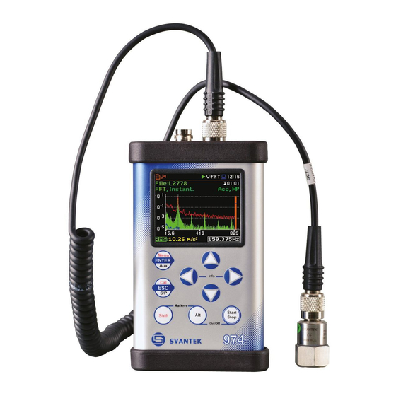
SVANTEK 974 User Manual Input and output sockets of the instrument Top cover of the instrument The instrument inputs, called Accelerometer and Probe are placed in the centre of the instrument’s top cover. The Accelerometer Input may work in three modes (Acceler. -
Page 12: General Information
SVANTEK 974 User Manual 3. GENERAL INFORMATION To perform measurements using the instrument the user only should connect the proper vibration transducer and to switch the power on by pressing the <Alt> and <Start/Stop> push-buttons at the same time. Hold both buttons down for 1 or 2 seconds and release to switch on. - Page 13 SVANTEK 974 User Manual Option list The option list consists of different choices, from which only one may be selected. The selection of the option is performed as follows. The user should highlight the desired option by means of the ▲ or ▼ push-buttons and then press <ENTER>.
- Page 14 SVANTEK 974 User Manual Text editor window In the text editor windows, the user may edit text lines (file names, directory name etc.) The text editor window is opened by pressing the ◄ or ► push-button when the position with the text parameter is selected.
-
Page 15: Powering Of The Instrument
3.2. Powering of the instrument The SVAN 974 can be powered by one of the following sources: • Four AA standard size internal batteries. In case of alkaline type, with a new fully charged set, the instrument can operate more than 12 h (6.0 V / 1.6 Ah). -
Page 16: Getting Started
SVANTEK 974 User Manual 3.3. Getting started Turning the instrument on To switch the power on the user should press the <Alt> and <Start/Stop> push-buttons at the same time. The instrument goes through the self-test routine after switching on, displaying during …... -
Page 17: Description Of Icons
SVANTEK 974 User Manual The logger and summary results will be automatically saved in the file with the name defined by the instrument and presented in the Logger Setup sub-list (Logger Name: LLxx). Default profiles settings: Profile 1 - HP1 weighting filter (Filter(1)=HP1); 1.0s RMS detector (Detector(1)=1.0s);... -
Page 18: Data Saving
SVANTEK 974 User Manual “note” icon is displayed when the wave “Trigger Level –“ icon is displayed when the “Level-” trigger is waiting for fulfilment recording is active (wave files with extension WAV are saved automatically) condition. The icon appears alternately with the “play”, “curve”... - Page 19 SVANTEK 974 User Manual The files are saved in the directory, which was set up as a working directory. The working directory is displayed in the bottom line of the File Manager window together with the memory icon. Directories are created manually with the use of <New Directory> position.
- Page 20 SVANTEK 974 User Manual The user can quickly jump to the directory where files were saved. To do this the user should make the field with file name active by means of ▲ or ▼ push-buttons and press <Enter>. <ENT>...
- Page 21 SVANTEK 974 User Manual Another option is to open the File Manager window (path: <Menu> / File / File Manger), select New File and press <ENTER>. <ENT> Note: Saving is not possible when the instrument is measuring the signal. The message “Measurement in progress!”...
-
Page 22: Files Downloading And Uploading
SVANTEK 974 User Manual 3.6. Files downloading and uploading Downloading files All files stored in the memory (micro SD Card) can be downloaded to the PC. There are two ways to download files. First way is to extract the micro SD Card and use it directly in the PC. -
Page 23: Functions Of The Instrument - Function
SVANTEK 974 User Manual 4. FUNCTIONS OF THE INSTRUMENT – Function To select the Function list, the user should press the <Menu> push-button, select the Function text and press <ENTER>. The Function list contains three elements: Mode, Measurement Function Calibration. -
Page 24: Instrument's Calibration - Calibration
SVANTEK 974 User Manual Instrument’s calibration – Calibration 4.3. The instrument is factory calibrated with the supplied accelerometers. In case of using other transducers calibration of the measurement channels should be performed by the user. Periodic calibration of standard accelerometers is also required. To select the calibration function, the user should enter the Calibration sub-list. -
Page 25: Calibration By Sensitivity
SVANTEK 974 User Manual The measurement starts after 3 second delay. The system check measurement time is also predefined to 5 seconds. During the calibration period, the <ESC> and <Pause> push-buttons do not operate but it is possible to stop the measurement using the <Start/Stop>... -
Page 26: History Of Performed Calibrations - Calibration History
SVANTEK 974 User Manual Attach the instrument’s accelerometer to the vibration calibrator using an appropriate or recommended fixing method. Switch on the calibrator and wait approximately 30 seconds before starting the calibration measurement. Start the calibration measurement by pressing the <Start/Stop> push- button. -
Page 27: Clearing Calibration Records - Clear Calibr. History
SVANTEK 974 User Manual 4.3.5. Clearing calibration records - Clear Calibr. History The user can clear all stored vibration calibration records. In order to do this the user has to choose the position Clear Calibr. History in the Calibration sub-list and press <ENTER>... -
Page 28: Setting Up The Measurement - Measurement
SVANTEK 974 User Manual 5. SETTING UP THE MEASUREMENT – Measurement The Measurement list contains the elements that enable the user to set up the measurement parameters. To open the Measurement list, the user has to press the <Menu> push-button, select Measurement text and press <ENTER>. - Page 29 SVANTEK 974 User Manual Disabling the measurement period definition The integration period can be set as infinite or can be defined together with the Repetition Cycles number. The Integr. Period Inf position defines if the period during which the signal is being measured is infinite or not. If the Integr.
-
Page 30: Setting Up The Measurement Trigger - Measurement Trigger
SVANTEK 974 User Manual Setting up the measurement trigger – Measurement Trigger The Measurement Trigger sub-list enables the user to set up parameters of the measurement trigger. Measurement Trigger is a context sub-list in which the triggering can be switched off or on... -
Page 31: Setting Up The Parameters For Profiles - Profiles
SVANTEK 974 User Manual Note: When measurement is waiting for the gradient or external trigger the “trigger” icon appears alternatively with the „play” icon. Source of the triggering signal Only one measured result can be used as a source of the triggering signal in the Level Meter mode, namely the output signal from the RMS detector coming from the first profile which is denoted here as Leq(1). -
Page 32: Setting Up The Data Logging - Logging
SVANTEK 974 User Manual The user can easily get into the Profiles screen during the measurement performance from the result view. It is necessary to enter some profile field (for example, P(1)) with the use of ▲ / ▼ or ◄ / ► push-buttons and press <ENTER>. -
Page 33: Setting Up The Logger General Parameters - Logger Setup
SVANTEK 974 User Manual The Logging list enables the user to program the logger functionality - recording of the measurement time history results; and program markers and parameters of the signal recording (event or wave). The Logging list consists of seven positions:... -
Page 34: Selection Of Results For Logging - Logger Results
SVANTEK 974 User Manual The edited name is accepted and saved after pressing the <ENTER> push-button. The special warning is displayed in case a file with the edited name already exists in the memory. The instrument waits then for a reaction of the user (any push-button should be pressed except <Shift>... -
Page 35: Selection Of Additional Summary Results For Saving - Summary Results
SVANTEK 974 User Manual 5.4.3 Selection of additional summary results for saving – Summary Results The Summary Results list enables the user to activate additional to the main results saving in the logger file: Max Spectrum and Min Spectrum. <ENT>... -
Page 36: Setting Up The Event Recording - Event Recording
SVANTEK 974 User Manual Level of the triggering signal The level of triggering signal for logging (Level) can be set with 1 dB steps in the range from 1mm/s (60 dB) to 10 km/s (200 dB). The Level value of the... - Page 37 SVANTEK 974 User Manual The Filter position displays the used weighting filter (HP) during event signal recording. The Trigger on Marker position switches on or off the triggering by marker. When Trigger on Marker is switched on then event recording will start by initiation of one of the user controlled markers.
-
Page 38: Setting Up The Markers - Marker Setup
SVANTEK 974 User Manual When Pre Trigger is higher than 0 then the event signal start to be recorded before the triggering condition moment. The period of such recording depends on the sample frequency and bits per sample. The maximum pre trigger period •... -
Page 39: Setting Up The Wave Recording - Wave Recording
SVANTEK 974 User Manual 5.4.7 Setting up the wave recording – Wave Recording The Wave Recording position enables the user to activate and to set the parameters of the raw time waveform recording in the special file with the extension WAV. The WAV files are saved automatically in the working directory on the memory (SD Card). -
Page 40: Setting Up The 1/1 Octave And 1/3 Octave Spectra - Spectrum
SVANTEK 974 User Manual If the Integr. Period trigger was defined, the signal is recorded every time the measurement starts and ended after the Integration Period time, defined in the General Settings window (path: <Menu> / Measurement / General Settings). -
Page 41: Checking The Measurement Range - Range
SVANTEK 974 User Manual Checking the measurement range – Range The Range position enables the user to check the available measurement range in the instrument. <ENT> There is one available measurement range: Single. The detailed description of the measurement range is given in Appendix C. -
Page 42: Programming The Instrument's Internal Timer - Timer
SVANTEK 974 User Manual Programming the instrument’s internal timer – Timer The Timer position enables the user to programme the internal real time clock to act as a delayed start and stop timer. The instrument can be switched on automatically... -
Page 43: Example Of Timer Execution
SVANTEK 974 User Manual Note: The Timer function can be used for multiple measurements (at the programmed day and time with the selected repetition number). The first start of the instrument must be within one month ahead. Make sure that the RTC is configured correctly before setting up the Timer. -
Page 44: Setting Up The Data View - Display
SVANTEK 974 User Manual 6. SETTING UP THE DATA VIEW – Display The Display list contains the elements that enable user independently programme the display parameters. The content of the Display list is different spectrum analyser functions (1|1 Octave, 1/3 Octave and FFT) in regards to the Level Meter function. - Page 45 SVANTEK 974 User Manual when the RMS Integration is exponential (path: <Menu> / Measurement / General Settings) 6. Units of the measured value 7. Function name: RMS, Ovl, Peak, P–P, MTVV 8. Elapsed time shows the current second of the measurement. The value presented there belongs to the range [1, Integration Period] Notice: There is no displayed indication of the detector in case of Peak, P-P and Ovl results.
- Page 46 SVANTEK 974 User Manual 6. Units of the measured value. 7. Elapsed time shows the current second of the measurement. The value presented there belongs to the range [1, Integration Period]. 8. File name when Logger is active (path: <Menu> /...
- Page 47 SVANTEK 974 User Manual Changing the active fields Changing the active field is made by pressing the ▲ / ▼ (vertically) or ◄ or ► (horizontally) push-buttons. ▼ Logger view The Logger view mode depends on the settings made in the Logging list (path: <Menu>...
-
Page 48: Setting Up The Units And Scale Of Results Presentation - Display Scale
SVANTEK 974 User Manual 6.2 Setting up the units and scale of results presentation - Display Scale The Display Scale sub-list enables the user to define the result units (absolute or logarithmic), adjust scale of plots and switch the grid on/off. -
Page 49: Setting Up The View Of The Logger Plot - Logger View
SVANTEK 974 User Manual Switching the grid on/off The Grid position enables the user to switch on or off the horizontal grid lines in any graphical presentation – history plot or spectrum. => The Decimal Mark position enables the user to select type of decimal mark: point or comma. - Page 50 SVANTEK 974 User Manual Power saver function The saving of the internal source of the instrument’s power can be achieved by reducing the brightness of the screen when possible. There are two options for the power saver function. The screen may be switched off (Screen off on idle) and/or dimmed (Dim screen on idle).
-
Page 51: Managing The Files - File
SVANTEK 974 User Manual 7. MANAGING THE FILES – File The File list enable the user to manage the data and setup files saved in the memory (micro SD Card). The File list contains the following items: <ENT> File Manager enables the user to manage the files saved on the SD card;... -
Page 52: Managing Files Saved In The Memory - File Manager
SVANTEK 974 User Manual 7.1 Managing files saved in the memory – File Manager The File Manager is used for checking the memory content, create new directories and files, select directory for saving files, delete files and directories. <ENT> The list of files and directories is presented in the File Manager window. -
Page 53: Opening File - Open
SVANTEK 974 User Manual 7.1.2 Opening file – Open The user can open logger file from the file list. To do this the user should select the file and press the <ENTER> push-button. After opening the command list select the Open position and press <ENTER>... -
Page 54: Renaming Files - Rename
If the Delete All command is performed in a root directory, then all files and directories will be erased except three directories: ALARM, SETUP and SVANTEK. These directories are always presented on a SD-disc. <ENT> 7.1.5 Renaming files – Rename The user can rename files or directories. - Page 55 SVANTEK 974 User Manual Saving the setup files It is possible to save only current instrument’s settings. To save current settings in the setup file the user should press <ENTER> on the Save Setup position and to edit the setup file name in the special window.
-
Page 56: Setting Up The Hardware Parameters - Instrument
SVANTEK 974 User Manual 8. SETTING UP THE HARDWARE PARAMETERS – Instrument The Instrument list is directly related to the settings of the hardware components of the instrument. To open the Instrument list, the user should press the <Menu> push-button, select the Instrument position and press <ENTER>. -
Page 57: Selection Of The Iepe Current Supply - Iepe Current
SVANTEK 974 User Manual Selection of the IEPE current supply - IEPE Current 8.3. The IEPE Current position enables the user to choose the correct IEPE current supply: IEPE Off or IEPE Current 1.5 mA and IEPE Current 4.5 mA <ENT>... - Page 58 SVANTEK 974 User Manual The I/O jack socket can be used as: • the output of the analogue signal (Analog Out) transmitted from the input of the instrument to its output without any digital processing (i.e. frequency filtering), • the input of the digital signal used as an external trigger to start the measurements (Digital In).
-
Page 59: Setting Up The Instrument's Internal Real Time Clock - Rtc
SVANTEK 974 User Manual Alarm source type The Source Type position enables the user to select the type of alarm source. Available types are: Current and Periodic. In case of Current, the alarm pulse will be generated all time when the instantaneous result of the function selected in the Source position (measured with 1 second step) is over the Alarm Level value. -
Page 60: Checking Of The Instrument Specification - Unit Label
▲ and ▼. <ENT> Note: The contents of the Unit Label window should be always sent to Svantek service department or official representative in case of any problems faced by the user during the instrument’s normal operation in the field. -
Page 61: Auxiliary Settings - Auxiliary Setup
SVANTEK 974 User Manual 9. AUXILIARY SETTINGS – Auxiliary Setup The Auxiliary Setup list provides the user with additional features that allow, for instance, customize the interface device to a specific user and are not directly related to the hardware components of the instrument. -
Page 62: Setting Up The Reference Levels - Reference Levels
SVANTEK 974 User Manual 9.3. Setting up the reference levels - Reference Levels The Reference Levels sub-list enables the user to set the reference levels of the vibration signal for acceleration (Acc), velocity (Vel) and displacement (Dil). The selected values will be considered during the calculations of the measurement results expressed in the Logarithmic scale (dB). - Page 63 SVANTEK 974 User Manual Checking free space on the external disk The Ext. Disk Free Space position switches on or off the verification of free space on the SD card and generates the warning when the space is lower than Min Free Space.
-
Page 64: And 1/3 Octave Analyser
SVANTEK 974 User Manual 10. 1/1 AND 1/3 OCTAVE ANALYSER The instrument operates as a real time 1/1 Octave or 1/3 Octave analyser (RTA) in a very similar way to the Level Meter. Moreover, 1/1 Octave or 1/3 Octave analysis is performed in parallel with the Level Meter operations. -
Page 65: Checking The Measurement Range For 1/1 Octave And 1/3 Octave - Range
SVANTEK 974 User Manual The 1/1 Octave or 1/3 Octave analysis is performed based on the parameters selected in the General Settings list of Measurement menu: Integration Period and Repetition Cycles. The spectra are stored as main results in a results file with the same step (Integr. -
Page 66: Saving The 1/1 Or 1/3 Octave Spectra As A Time History - Logger Results
SVANTEK 974 User Manual The Band position defines the applied band of 1/1 Octave or 1/3 Octave analysis: • 1/1 Octave: Full (1-16k) - 15 filters with centre frequencies 1 Hz ÷16 kHz, • 1/3 Octave: Full (0.8-20k) - 45 filters with centre frequencies 0.8 Hz ÷20 kHz. -
Page 67: Presentation Of 1/1 Octave And 1/3 Octave Spectra
SVANTEK 974 User Manual 10.4.1. Presentation of 1/1 Octave and 1/3 Octave spectra Spectrum position Display Modes list becomes available for the 1/1 Octave and 1/3 Octave functions and enables the user to switch on or off the spectrum view. -
Page 68: Selection Of The Spectra To Be Viewed - Spectrum View
SVANTEK 974 User Manual Scale of results presentation The Scale position defines the units of results: Lin (linear) and Log (logarithmic). In case of Log the graphical presentation is given in the logarithmic scale and the measurement results are expressed in decibels (the result is related to the values =>... -
Page 69: Selection Of The Spectrum Type - Spectrum Type
SVANTEK 974 User Manual To enable the cursor to read the Max or Min values the user should select the field in the lower left hand corner of the display by means of the ▲ or ▼ push-buttons. Then select the appropriate value by means of the ◄... -
Page 70: Fft Analyser
SVANTEK 974 User Manual 11. FFT ANALYSER The instrument operates as FFT analyser in a very similar way to the Level Meter. Moreover, FFT analysis is performed in parallel with the Level Meter operations. The results of FFT analysis (spectra) can be examined by the user on a display in the Spectrum view. -
Page 71: Checking The Measurement Range Of Fft Analisys - Range
SVANTEK 974 User Manual 11.2.1. Checking the measurement range of FFT analisys - Range For the FFT function there is only one (Single) input range specified Appendix C. The user can check it in the Range window of the Measurement list. -
Page 72: Saving The Fft Spectra As A Time History - Logger Results
SVANTEK 974 User Manual The user can easily get into the FFT screen from the spectrum view. It is necessary to enter the function field (FFT) with the use of ▲ or ▼ push-buttons and press <ENTER>. <ENT> Peak detection The peak detection is designed to find peaks in the FFT spectrum. -
Page 73: Presentation Of Fft Spectra
SVANTEK 974 User Manual Display Scale enables the user to change the scale of the vertical and horizontal axis of the spectrum plot, switch on or off the grid; Spectrum View enables the user to choose the spectrum (Average, Instantaneous, Min, Max) to be viewed;... -
Page 74: Setting Up The Scale Of Spectrum Plot - Scale
SVANTEK 974 User Manual 11.4.2. Setting up the scale of spectrum plot - Scale The Display Scale sub-list enables the user to change the scale of the spectrum plot, switch the grid on or off. The user can also define Decimal Mark... -
Page 75: Selection Of The Spectra To Be Viewed - Spectrum View
SVANTEK 974 User Manual 11.4.3. Selection of the spectra to be viewed - Spectrum View In the Spectrum View window, the user can select the different spectra to be visible on the display. In the Spectrum View window the following spectrum types may be selected: Averaged, Instantaneous, Max or Min. -
Page 76: Maintenance
NiMH type, the operation time can be increased up to 16 h (4.8 V / 2.6 Ah) • USB interface – 500 mA HUB SVAN 974 is delivered with four AA alkaline batteries, but the user may also use AA rechargeable batteries. The “battery” icon shows the condition of the internal batteries. -
Page 77: Transducers
While insertion the SD-card, a click sound indicates that the card is inserted properly. If necessary, use a tool (e.g. pen) to push the card right in. 12.3. Transducers SVAN 974 is equipped with the TNC connector as an input of the measured signal taken from the vibration transducer. Another connector is used for the tacho probe. -
Page 78: Firmware Upgrade
SVANTEK 974 User Manual 12.5. Firmware upgrade SVANTEK is committed to continuous innovation path of development, and as such reserves the right to provide firmware enhancements based on user’s feedback. To update the instrument firmware: • Unpack the provided firmware package. (provided as a suitable compressed file). - Page 79 SVANTEK 974 User Manual Service Office: +48 (22) 51-88-320 or +48 (22) 51-88-322. Office hours are 8:00 a.m. to 4:00 p.m. Central European Time. E-mail at office@svantek.com Internet at www.svantek.com Address: SVANTEK Sp. z o.o. Strzygłowska 81 04-872 Warszawa, Poland...
Need help?
Do you have a question about the SVAN 974 and is the answer not in the manual?
Questions and answers