Vivo DESK-V123EB Instruction Manual
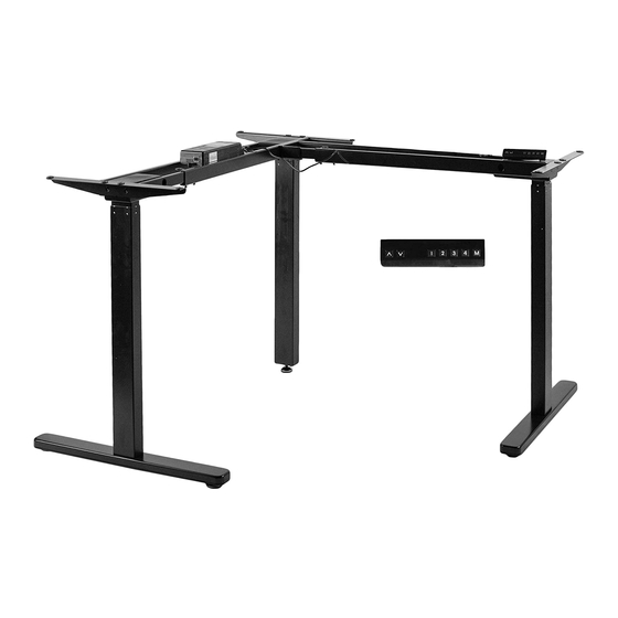
Electric multi motor corner desk frame
Hide thumbs
Also See for DESK-V123EB:
- Instruction manual (8 pages) ,
- Instruction manual (8 pages) ,
- Instruction manual (4 pages)
Advertisement
Quick Links
Electric Multi Motor Corner Desk Frame
Instruction Manual
SKU: DESK-V123EB/EW
Scan the QR code with your mobile device or follow the link
for helpful videos and specifications related to this product.
https://vivo-us.com/products/desk-v123eb
GET IN TOUCH | Monday-Friday from 7:00am-7:00pm CST
help@vivo-us.com
www.vivo-us.com
Chat live with an agent!
309-278-5303
Advertisement

Related Manuals for Vivo DESK-V123EB


Summary of Contents for Vivo DESK-V123EB
- Page 1 Electric Multi Motor Corner Desk Frame Instruction Manual SKU: DESK-V123EB/EW Scan the QR code with your mobile device or follow the link for helpful videos and specifications related to this product. https://vivo-us.com/products/desk-v123eb GET IN TOUCH | Monday-Friday from 7:00am-7:00pm CST help@vivo-us.com...
-
Page 2: Electrical Safety Instructions
WARNING! If you do not understand these directions, or if you have any doubts about the safety of the installation, please call a qualified technician. Check carefully to make sure there are no missing or defective parts. Improper installation may cause damage or serious injury. -
Page 3: Tools Needed
TOOLS NEEDED DO NOT EXCEED WEIGHT CAPACITY. 264lbs Phillips Failure to do so may result in serious injury. Drill (120kg) Screwdriver ASSEMBLY STEPS STEP 1 Attach Feet (A) to the underside of Motorized Legs (B) using M6x35mm Screws (S-E) and 5mm Allen Wrench (T-A). - Page 4 STEP 3 Connect Inner Crossbar (F) and Crossbar With Plate (G) to another Motorized Leg (B) using M6x11mm Screws (S-B) and 5mm Allen Wrench (T-A). STEP 4 Slide crossbars from leg assemblies together. These will be secured in a later step. Secure Extension Connector (D) to the side of Crossbar With Plate (G) using M8x12mm Screws (S-C) and 5mm Allen Wrench (T-A).
- Page 5 STEP 5 Connect Outer Extension Crossbar (H) and Innter Extension Crossbar (I) to Extension Connector (D) using M6x11mm Screws (S-B) and 5mm Allen Wrench (T-A). Assemble Inner Crossbar (F) and Outer Crossbar (E) to remaining Motorized Leg (B) using M6x11mm Screws (S-B) and 5mm Allen Wrench (T-A).
- Page 6 STEP 6 Adjust frame to fit desired desktop size and secure the following crossbars in place using M6x11mm Screws (S-B) and 5mm Allen Wrench (T-A): Crossbar With Plate (G), Outer Crossbars (E), and Outer Extension Crossbar (H). STEP 7 Attach Side Brackets (C) to outside edge of Motorized Legs (B) using M6x11mm Screws (S-B) and 5mm Allen Wrench (T-A).
- Page 7 STEP 8 Attach Anti-Vibration Pads (P) to desktop mounting holes in the side brackets and crossbars. Optional If needed, use provided Tabletop Connectors (O) and M5x16mm Screws (S-A) to secure desktop pieces together. Note: Desktop is not provided.
- Page 8 STEP 9 Place assembled frame upside down on the desktop. Drill 10mm deep pilot holes using a 1/8” (3mm) drill bit, and secure using M5x16mm Screws (S-A) and a Phillips screwdriver. Mark screw locations for Controller (J) and Control Unit (K), making sure the controller cable is able to reach the box, then drill 10mm deep pilot holes using a 1/8”...
- Page 9 STEP 10 Connect cables from Controller (J) and Motorized Legs (B) to the Control Unit (K). If needed, use Extension Cables (M, N) to connect legs. Connect Power Cable (L) to Control Unit (K) and plug into an AC power outlet. Adjust Foot Pads (R) to sit level if necessary. Add Cable Clips (Q) as needed.
- Page 10 CAUTION! Do not exceed desk Keep area of vertical Keep weight on desk Leave enough slack in weight limit. motion free of balanced for correct cables to allow for full obstacles. operation and longer range of vertical motion. life of components. Failure to follow these instructions may result in property damage and/or personal injury.
- Page 11 THIS PAGE INTENTIONALY LEFT BLANK...
- Page 12 : 1HR 8M (within office hrs) - 23% within < 15m - 38% within < 30m - 61% within < 1hr - 83% within < 2hr - 92% within < 3hr FOR MORE VIVO PRODUCTS, CHECK OUT OUR WEBSITE AT: www.vivo-us.com...
Need help?
Do you have a question about the DESK-V123EB and is the answer not in the manual?
Questions and answers