Rockwell Automation Allen-Bradley Armor GuardLogix 1756-L72EROMS Installation Instructions Manual
Hide thumbs
Also See for Allen-Bradley Armor GuardLogix 1756-L72EROMS:
- Quick start manual (200 pages)
Table of Contents
Advertisement
Quick Links
Installation Instructions
Original Instructions
Armor GuardLogix Controllers
Catalog Numbers
1756-L72EROMS, 1756-L73EROMS
Topic
Summary of Changes
Before You Begin
Install the Armor GuardLogix Controller
Mount the Controller
Ground the Controller
Open the Access Door
Remove and Install the Memory Card
Connect to the USB Port
Make Network Connections
Make Power Connections
Set the Network IP Address of the EtherNet/IP Modules
Update the Controller
Status Indicators
Recover the Controller By Using a Memory Card
Specifications
Additional Resources
Page
1
4
5
5
6
7
7
8
8
9
10
15
16
16
17
18
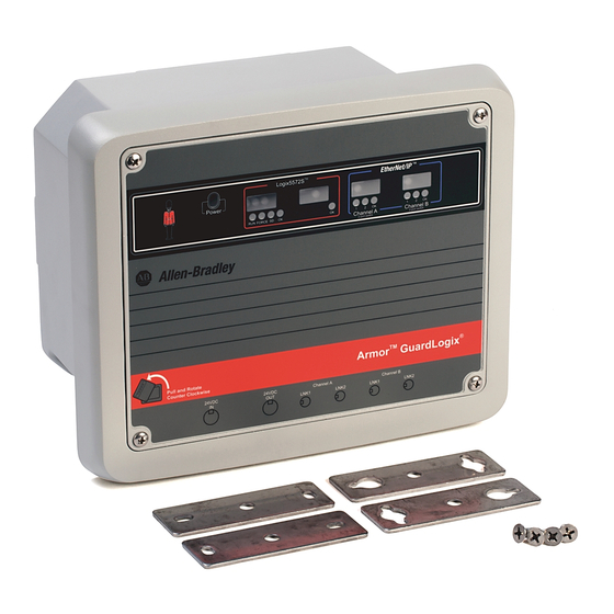
The Armor™ GuardLogix® controller combines a 1756-L72S or 1756-L73S GuardLogix
controller and safety partner with two EtherNet/IP™ DLR-capable 1756-EN3TR
communication modules in an IP67-rated housing for mounting on a machine.
The Armor GuardLogix controller is certified for use in safety applications up to
Display
and including Safety Integrity Level (SIL) 3 and Performance Level (e) in which the
Window
de-energized state is the safe state. The safety features of the Armor GuardLogix
controller are derived from the sum of all components within the enclosure.
For information on how to operate a GuardLogix controller-based system,
safety application requirements, and where to find the GuardLogix certificate,
see
Additional Resources on page
Access
Door
Screws
Summary of Changes
We added the 1756-L73EROMS controller to this publication.
18.
Advertisement
Table of Contents

Related Manuals for Rockwell Automation Allen-Bradley Armor GuardLogix 1756-L72EROMS


Summary of Contents for Rockwell Automation Allen-Bradley Armor GuardLogix 1756-L72EROMS
- Page 1 Installation Instructions Original Instructions Armor GuardLogix Controllers Catalog Numbers 1756-L72EROMS, 1756-L73EROMS Topic Page Summary of Changes Before You Begin Install the Armor GuardLogix Controller Mount the Controller Ground the Controller Open the Access Door Remove and Install the Memory Card Connect to the USB Port Make Network Connections Make Power Connections...
- Page 2 Indien de apparatuur wordt gebruikt op een wijze die niet is gespecificeerd door de fabrikant, dan bestaat het gevaar dat de beveiliging van de apparatuur niet goed werkt. Rockwell Automation Publication 1756-IN060D-EN-P - February 2017...
- Page 3 • IEC 60950-1 Ed. 2.1, Clause 2.2 - SELV Circuits ATTENTION: In case of malfunction or damage, no attempts at repair should be made. The controller should be returned to the manufacturer for repair. Do not dismantle the controller. Rockwell Automation Publication 1756-IN060D-EN-P - February 2017...
-
Page 4: Before You Begin
The two EtherNet/IP communication modules in the enclosure let you use the Armor GuardLogix controller in various EtherNet/IP network topologies, including linear, star, and device-level ring (DLR) as a ring node or ring supervisor. For more information on EtherNet/IP networks, see the publications that are listed in Additional Resources on page Rockwell Automation Publication 1756-IN060D-EN-P - February 2017... -
Page 5: Mount The Controller
Mount the module directly to a machine by using four mounting holes. The mounting hole diameter is 6.8 mm (0.27 in.) on the mounting feet that are included with the enclosure. Use four M6 screws and torque screws to 6.6 N•m (58 lb•in). See the Product Dimensions on page Rockwell Automation Publication 1756-IN060D-EN-P - February 2017... -
Page 6: Ground The Controller
Tighten the screw. Wire Size Torque PE Ground 1.3…5.2 mm (#16…#10 AWG) 2 N•m (17.7 lb•in) See Industrial Automation Wiring and Grounding Guidelines, publication 1770-4.1 for guidelines on how to install an industrial control system. Rockwell Automation Publication 1756-IN060D-EN-P - February 2017... -
Page 7: Open The Access Door
2. Verify that the memory card is locked or unlocked according to your preference. Unlocked Locked 3. Insert the memory card into the memory card slot. 4. Gently press the card until it clicks into place. 5. Close the enclosure access door. Rockwell Automation Publication 1756-IN060D-EN-P - February 2017... -
Page 8: Connect To The Usb Port
Pin 4 – M12_Rx- Pin 5 – Connector Shell Shield GND 44236 IMPORTANT Use the 1585D–M4DC–H: Polyamide small-body unshielded or the 1585D–M4DC–SH: Zinc die-cast large-body shielded mating connectors for the D-Code M12 female network connector. Rockwell Automation Publication 1756-IN060D-EN-P - February 2017... -
Page 9: Make Power Connections
1. Remove the dust cap from the female power connector on the bottom of the enclosure. IMPORTANT If you disconnect power connections from these ports, reattach the dust cap and finger-tighten. 2. Make power connections and tighten to hand tight plus one half-turn. Rockwell Automation Publication 1756-IN060D-EN-P - February 2017... -
Page 10: Set The Network Ip Address Of The Ethernet/Ip Modules
3. Type the Subnet Mask of the network. The Gateway address, Primary and/or Secondary DNS address, and Domain Name fields are optional. 4. Click OK. The Request History panel shows the hardware addresses of all modules issuing BOOTP requests. Rockwell Automation Publication 1756-IN060D-EN-P - February 2017... - Page 11 8. To assign this configuration to the module permanently, wait for the module to appear in the Relation List panel and select it. 9. Click Disable BOOTP/DHCP. IMPORTANT If you do not click Disable BOOTP/DHCP, the host controller clears the current IP configuration and begins sending BOOTP requests again each time that power is cycled. Rockwell Automation Publication 1756-IN060D-EN-P - February 2017...
- Page 12 If you click either automatic option, on a power cycle, the controller clears the current IP configuration and resumes sending BOOTP requests. 9. Type the IP address in the IP Address field. 10. Click OK. Rockwell Automation Publication 1756-IN060D-EN-P - February 2017...
- Page 13 2. Create a controller project that includes all of the components in the enclosure. 3. Download the project. 4. Go online with the controller. 5. In the Controller Organizer, right-click the EtherNet/IP module and choose Properties. Rockwell Automation Publication 1756-IN060D-EN-P - February 2017...
- Page 14 The fields that appear vary from one EtherNet/IP module to another. 9. Click Set. You see a warning that prompts you to confirm that you want to change the IP address. 10. Click Yes. 11. Click OK. Rockwell Automation Publication 1756-IN060D-EN-P - February 2017...
-
Page 15: Update The Controller
The controller ships without firmware. Controller firmware is packaged with the Studio 5000 environment. In addition, controller firmware is also available for download from the Rockwell Automation Technical Support website at: http://www.rockwellautomation.com/support/. You can update your firmware by using either ControlFLASH™ software or by using the AutoFlash feature of the Logix Designer application. -
Page 16: Status Indicators
1. Remove the memory card that came with the controller. 2. Insert the recovery memory card. 3. Cycle power to the controller. The blank project on the recovery memory card overwrites the project in the controller. Rockwell Automation Publication 1756-IN060D-EN-P - February 2017... -
Page 17: Specifications
The following standards, and technical specifications have been applied as indicated. Standard/Technical Specification EN 60204-1 Electrical equipment of machines EN ISO 13849-1 Safety-related parts of control systems EN 62061 Functional Safety of safety-related control systems Rockwell Automation Publication 1756-IN060D-EN-P - February 2017... -
Page 18: Additional Resources
Networks publication ENET-AP005 Rockwell Automation EtherNet/IP devices that are equipped with embedded switch technology. EtherNet/IP Media Planning and Installation Manual Provides details about how to use the required media components and how to plan for, install, verify, troubleshoot, This manual is available from the Open DeviceNet Vendor and certify your EtherNet/IP network. - Page 19 Armor GuardLogix Controllers Notes: Rockwell Automation Publication 1756-IN060D-EN-P - February 2017...
-
Page 20: Rockwell Automation Support
Rockwell Automation maintains current product environmental information on its website at http://www.rockwellautomation.com/rockwellautomation/about-us/sustainability-ethics/product-environmental-compliance.page. Allen-Bradley, Armor, ArmorStart, ControlFLASH, ControlLogix, GuardLogix, Logix5000, On-Machine, Rockwell Automation, Rockwell Software, RSLinx, Studio 5000, and Studio 5000 Logix Designer are trademarks of Rockwell Automation, Inc. EtherNet/IP is a trademark of ODVA, Inc.
Need help?
Do you have a question about the Allen-Bradley Armor GuardLogix 1756-L72EROMS and is the answer not in the manual?
Questions and answers