Table of Contents
Advertisement
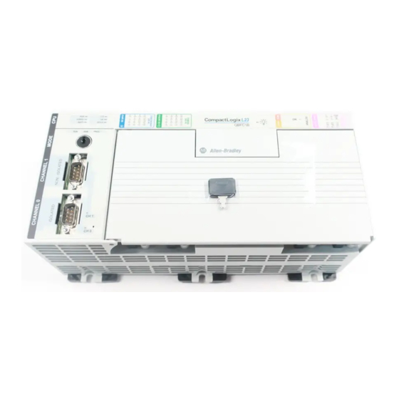
CompactLogix Packaged Controllers
Catalog Numbers 1769-L23E-QB1B, 1769-L23E-QBFC1B, 1769-L23-QBFC1B
Topic
Important User Information
Before You Begin
Restrictions
Parts
Required System Components
Installation Checklist
Packaged Controller Dimensions
Install the Battery
Connect Expansion Modules (optional)
Panel Mount the System
DIN-rail Mount the System
Wiring Power to the System
Wire the I/O Removable Terminal Blocks
Expansion Module Wiring
Connect Using the RS-232 Connection
Connect Using the Ethernet Connection
Download and Install EDS Files
Download Packaged Controller Firmware
Use the AutoFlash Feature of RSLogix 5000 to Load Firmware
Use the ControlFlash Utility to Load Firmware
Select the Packaged Controller's Operating Mode
Status Indicators
Specifications
Additional Resources
Installation Instructions
Page
2
4
4
5
6
7
8
10
11
13
13
15
16
27
27
28
29
29
29
33
36
37
45
59
Advertisement
Table of Contents

Related Manuals for Rockwell Automation 1769-L23E-QB1B


Summary of Contents for Rockwell Automation 1769-L23E-QB1B
- Page 1 Installation Instructions CompactLogix Packaged Controllers Catalog Numbers 1769-L23E-QB1B, 1769-L23E-QBFC1B, 1769-L23-QBFC1B Topic Page Important User Information Before You Begin Restrictions Parts Required System Components Installation Checklist Packaged Controller Dimensions Install the Battery Connect Expansion Modules (optional) Panel Mount the System DIN-rail Mount the System...
-
Page 2: Compactlogix Packaged Controllers
In no event will Rockwell Automation, Inc. be responsible or liable for indirect or consequential damages resulting from the use or application of this equipment. -
Page 3: North American Hazardous Location Approval
CompactLogix Packaged Controllers North American Hazardous Location Approval The following information applies when operating Informations sur l’utilisation de cet équipement en this equipment in hazardous locations. environnements dangereux. Products marked "CL I, DIV 2, GP A, B, C, D" are suitable for use in Les produits marqués "CL I, DIV 2, GP A, B, C, D"... -
Page 4: Prevent Electrostatic Discharge
Each packaged controller has a specified amount of available bus current as shown in this table. Packaged Controller Bus Current and Expansion Module Limits Cat. No. Total Available 5V DC Bus Current 1769-L23E-QB1B 1 A (1000 mA) 1769-L23E-QBFC1B 450 mA 1769-L23-QBFC1B... -
Page 5: Parts
CompactLogix Packaged Controllers Example of Expansion I/O Calculation: In this example, these expansion I/O modules and bus current draws are planned for use with the 1769-L23E-QBFC1B packaged controller. Planned Expansion I/O Module Bus Current Draw, max 1769-OV16 Sink Output Module 200 mA 1769-IF4 Analog Input Module 105 mA... -
Page 6: Required System Components
CompactLogix Packaged Controllers Replacement Parts These CompactLogix packaged controller replacement parts are available for order. Catalog No. Description Compatible Packaged Controllers 1769-BA CompactLogix packaged controller 1769-L23E-QB1B, 1769-L23E-QBFC1B, and battery 1769-L23-QBFC1B 1769-ECR Compact right end cap 1769-L23E-QB1B, 1769-L23E-QBFC1B, and 1769-L23-QBFC1B 1769-RDQB... -
Page 7: Installation Checklist
CompactLogix Packaged Controllers Installation Checklist This table lists tasks that must be completed to fully install and begin using your packaged controller. Installation Tasks Install the Battery Connect Expansion Modules (optional) Panel Mount the System or DIN-rail Mount the System Minimum Spacing Requirements Grounding Considerations Wire the I/O Removable Terminal Blocks... -
Page 8: Packaged Controller Dimensions
CompactLogix Packaged Controllers Packaged Controller Dimensions 1769-L23E-QB1B Packaged Controller The 1769-L23E-QB1B controller has these approximate dimensions. CompactLogix L23E Measurement Dimension, approx. 185.2 mm (7.29 in) 123.86 mm (4.88 in) 118 mm (4.65 in) 132 mm (5.20in) 132.9 mm (5.23 in) 18 mm (.71 in) - Page 9 CompactLogix Packaged Controllers 1769-L23E-QBFC1B and 1769-L23-QBFC1B Packaged Controllers The 1769-L23E-QBFC1B and 1769-L23-QBFC1B packaged controllers have these approximate dimensions. CompactLogix L23E CompactLogix L23 FORCE BATT DCH 0 Measurement Dimension, approx. 249.25 mm (9.81 in) 123.86 mm (4.88 in) 118 mm (4.65 in) 132 mm (5.20in) 98.475 mm (3.88 in) 98.475 mm (3.88 in)
-
Page 10: Install The Battery
CompactLogix Packaged Controllers Install the Battery Complete these steps to install the battery on your packaged controller. When you connect or disconnect the battery an electrical arc can occur. This could cause WARNING an explosion in hazardous location installations. Be sure that the area is nonhazardous before proceeding. -
Page 11: Connect Expansion Modules (Optional)
CompactLogix Packaged Controllers Connect Expansion Modules (optional) If using expansion modules with your packaged controller, complete these steps to attach the modules. 1. Remove the end cap by unlocking it and sliding it forward. 2. Align the tongue-and-groove slots of the expansion module with those on the right end of the packaged controller. -
Page 12: Minimum Spacing Requirements
CompactLogix Packaged Controllers 6. Align the tongue-and-groove slots of the end cap with those on the right of the packaged controller or expansion module. 7. Close the locking tab located on the top of the end cap. Minimum Spacing Requirements When using any of the CompactLogix packaged controllers, maintain spacing from enclosure walls, wireways, and adjacent equipment. -
Page 13: Panel Mount The System
CompactLogix Packaged Controllers Panel Mount the System To mount your system to a panel, complete these steps. 1. Using the assembled system as a template, carefully mark the center of all mounting holes on the panel. 2. Remove the system and drill and tap the mounting holes for the recommended M4 or #8 screws. -
Page 14: Grounding Considerations
CompactLogix Packaged Controllers 2. Press the DIN rail mounting area of the packaged controller against the DIN rail. The latches momentarily open and lock into place on the DIN rail 3. Press the DIN rail mounting area of the packaged controller against the DIN rail. -
Page 15: Wiring Power To The System
CompactLogix Packaged Controllers Wiring Power to the System Use this diagram as a reference when wiring the required 24V DC power to your system. • Do not connect directly to line voltage. Line voltage must be supplied by a suitable, WARNING approved isolating transformer or power supply having short-circuit capacity not exceeding 100 VA maximum or equivalent. -
Page 16: Wire The I/O Removable Terminal Blocks
CompactLogix Packaged Controllers Wire the I/O Removable Terminal Blocks • When you connect or disconnect the Removable Terminal Block (RTB) with field side WARNING power applied, an electrical arc can occur. This could cause an explosion in hazardous location installations. •... -
Page 17: Dc Inputs Wiring Diagram
CompactLogix Packaged Controllers DC Inputs Wiring Diagram + DC (sinking) - DC (sourcing) 24V DC + DC (sinking) + DC (sinking) - DC (sinking) - DC (sourcing) - DC (sourcing) + DC (sourcing) 24V DC - DC (sinking) + DC (sourcing) Sinking/Sourcing Inputs - Sourcing/sinking describes the current flow between the I/O and the field device. - Page 18 CompactLogix Packaged Controllers (1)(2) DC Outputs Wiring Diagram +VDC OUT 0 OUT 1 OUT 2 OUT 3 OUT 4 OUT 5 OUT 6 OUT 7 OUT 8 24Vdc (source) OUT 9 OUT 10 OUT 11 OUT 12 OUT 13 OUT 14 OUT 15 DC COM Recommended Surge Suppression - Use a 1N4004 diode reverse-wired across the load for transistor outputs switching 24V...
- Page 19 CompactLogix Packaged Controllers Analog I/O Wiring Diagrams Read and consider this information before wiring your analog I/O. Analog outputs may fluctuate for less than a second when power is applied or removed. ATTENTION This characteristic is common to most analog outputs. While the majority of loads will not recognize the short signal, take preventive measures to ensure that connected equipment is not affected.
- Page 20 CompactLogix Packaged Controllers Differential Input Wiring Diagram Belden 8761 cable (or equivalent) V in 0+ V in 1+ Differential Voltage V/I in 0- Transmitter – V/I in 1 - I in 0+ I in 1+ Earth ground the V in 2 + shield locally at the V in 3+ module.
- Page 21 CompactLogix Packaged Controllers Mixed-input Transmitter Wiring Diagram Analog I/O Terminal Block Signal Single-ended Voltage V in 0+ Transmitter I in 0+ – V/I in 0 - V in 1+ I in 1+ Differential Signal V/I in 1- Voltage – Transmitter V in 2+ I in 2+ –...
-
Page 22: High-Speed Counter Wiring Diagrams
CompactLogix Packaged Controllers High-speed Counter Wiring Diagrams Read and consider this information before wiring your high-speed counter. ATTENTION Disconnect power before wiring the HSC removable terminal block. This includes sensor and packaged controller power. • Input and output channels are isolated from the packaged controller. Input channels are isolated from one another;... - Page 23 CompactLogix Packaged Controllers HSC Differential Encoder Wiring Cable +VDC Power Supply A1(+) A1(–) B1(+) B1(–) Allen-Bradley Z1(+) 845H Series Z1(–) Differential Encoder Shield Shield/housing Earth Connect only if housing is electronically isolated from the motor and ground. Inputs Refer to your encoder manual for proper cable type. The type of cable used should be twisted pair, individually shielded cable with a maximum length of 300 m (1000 ft.).
- Page 24 CompactLogix Packaged Controllers HSC Single-ended Encoder Wiring Diagram Cable +VDC Power Supply A1(+) A1(–) B1(+) Allen-Bradley B1(–) 845H Series Z1(+) Single-ended Z1(–) Encoder Shield Inputs Shield/housing Earth Connect only if housing is electronically isolated from the motor and ground. Refer to your encoder manual for proper cable type. The type of cable used should be twisted-pair, individually shielded cable with a maximum length of 300 m (1000 ft.).
- Page 25 CompactLogix Packaged Controllers HSC Discrete Device Wiring +VDC Power Supply Proximity Sensor A1(+) A1(–) Solid-state B1(+) Switch B1(–) Z1(+) Z1(–) Photo-electric Sensor with Open Module Inputs Collector Sinking Output External resistors are required if they are not internal to the sensor. The pull-up resistor (R) value depends on the power supply value.
- Page 26 CompactLogix Packaged Controllers HSC Output Wiring Basic wiring of HSC outputs is shown below. ATTENTION Mis-wiring the embedded HSC to an AC power source or applying reverse polarity causes damage to the embedded HSC. OUT DC +5/24VDC OUT 0 OUT 1 OUT 2 OUT 3 DC COM...
-
Page 27: Expansion Module Wiring
Use the wiring diagrams specific to your expansion module. Module wiring diagrams are available at http://literature.rockwellautomation.com. Connect Using the RS-232 Connection 1769-L23E-QB1B, 1769-L23-QBFC1B, and 1769-L23E-QBFC1B controllers WARNING If you connect or disconnect the serial cable with power applied to this module or the serial device on the other end of the cable, an electrical arc can occur. -
Page 28: Connect Using The Ethernet Connection
CompactLogix Packaged Controllers Connect Using the Ethernet Connection 1769-L23E-QB1B and 1769-L23E-QBFC1B controllers Complete these steps to connect to the controller using the Ethernet connection. WARNING If you connect or disconnect the Ethernet cable with power applied to this module or any device on the network, an electrical arc can occur. -
Page 29: Download And Install Eds Files
CompactLogix Packaged Controllers Download and Install EDS Files If you have RSLinx software, version 2.52 or later, the most current EDS files were installed with the software. If you are using an earlier version of RSLinx software, you need to download and install EDS files specific to each component of the packaged controller. - Page 30 CompactLogix Packaged Controllers 4. Select your packaged controller and click Download. You may also choose to click Update Firmware to complete this process. If you do so, skip to step 8. A dialog box displays indicating that the project revision and controller firmware revision are different.
- Page 31 CompactLogix Packaged Controllers 6. Use the checkbox and pull-down to select your controller and firmware revision. 7. Click Update. 8. Click Yes. The firmware upgrade begins. DO NOT INTERUPT THE FIRMWARE UPGRADE ONCE IT HAS BEGUN. IMPORTANT Interupting the firmware upgrade may result in an inoperable packaged controller. Publication 1769-IN082A-EN-P - July 2008...
- Page 32 CompactLogix Packaged Controllers During the firmware upgrade you see the status change as shown below. Status Change Continue to allow the firmware upgrade to complete without interuption. When the firmware upgrade is complete, the Download dialog displays and you may continue by dowloading your project to the packaged controller. Publication 1769-IN082A-EN-P - July 2008...
-
Page 33: Use The Controlflash Utility To Load Firmware
CompactLogix Packaged Controllers Use the ControlFlash Utility to Load Firmware You can use the ControlFlash utility to load firmware via an Ethernet (preferred) or serial connection. When upgrading your packaged controller firmware, it is extremely important to allow IMPORTANT the upgrade to complete without interruption. If you interrupt the upgrade either in ControlFlash software or by disturbing the physical media, you may render the packaged controller inoperable. - Page 34 CompactLogix Packaged Controllers 8. Click Finish and then click Yes. The firmware upgrade begins. DO NOT INTERUPT THE FIRMWARE UPGRADE ONCE IT HAS BEGUN. IMPORTANT Interupting the firmware upgrade may result in an inoperable packaged controller. During the firmware upgrade you see the status change as shown below. Status Change Status...
- Page 35 CompactLogix Packaged Controllers The Upgrade Status dialog box indicates that the firmware upgrade has been successfully completed. 9. Click OK. 10. To close the ControlFlash utility, click Cancel and then click Yes. Publication 1769-IN082A-EN-P - July 2008...
-
Page 36: Select The Packaged Controller's Operating Mode
CompactLogix Packaged Controllers Select the Packaged Controller’s Operating Mode Use the keyswitch on the front panel of the packaged controller to select the packaged controller’s operating mode. This table explains the three modes (keyswitch positions) available on the front panel of the packaged controller. Operating Mode Selection Use this operating... -
Page 37: Power Supply Status Indicator
CompactLogix Packaged Controllers Power Supply Status Indicator The green power supply status indicator is located next to the lightbulb symbol and indicates these power states. • ON = +5 and +24V DC current available from power supply • Off = No input power, power-fail enabled, or overvoltage exceeded/protection enabled Packaged Controller Status Indicators The six packaged controller status indicators are located at the top left corner of the... -
Page 38: Controller Status Indicators
CompactLogix Packaged Controllers Controller Status Indicators Indicator Status Description BATT The battery supports memory. Steady red The battery is either: • not installed. • 95% discharged and should be replaced. Either: • There are no devices in the I/O configuration of the packaged controller. - Page 39 CompactLogix Packaged Controllers Controller Status Indicators Indicator Status Description OK (con’t) Steady red Upon power-up, the OK indicator is steadily red for a few moments. This is normal behavior and is not a fault. If the OK indicator is steadily red for more than a few moments or changes to steadily red while in use, then a nonrecoverable major fault has occurred and project memory has been cleared.
-
Page 40: Module Status (Ms) Indicator
CompactLogix Packaged Controllers Module Status (MS) Indicator The Module Status (MS) indicator is located under the space provided for you to write the IP address of the packaged controller and is one of the Ethernet/IP network status indicators. Use this table as a reference when interpreting your MS indicator. Status Description Take this action... -
Page 41: Network Status (Ns) Indicator
CompactLogix Packaged Controllers Network Status (NS) Indicator The Network Status (NS) indicator is located to the right of the Ethernet port and is one of the EtherNet/IP status indicators. Use this table as a reference when interpreting the NS indicator. Status Description Take this action... -
Page 42: Link Status (Lnk) Led Indicator
CompactLogix Packaged Controllers Link Status (LNK) LED Indicator The Link (LNK) status indicator is also located to the right of the Ethernet port, below the NS indicator. It is also an EtherNet/IP network status indicator. Use this table as a reference when interpreting your LNK indicator. Status Description Take this action... -
Page 43: Rs-232 Serial Port Status Indicators
CompactLogix Packaged Controllers RS-232 Serial Port Status Indicators Two serial port status indicators (the 1769-L23-QBFC1B has three) are present on the left side of each CompactLogix packaged controller. FORCE BATT DCH 0 CH 1 CH 0 Use this table as a reference when interpreting any of the serial port status indicators. -
Page 44: I/O Status Indicators
CompactLogix Packaged Controllers I/O Status Indicators Use this section to interpret your I/O status indicators. DC Inputs DC Outputs Power Supply Status Analog I/O CompactLogix L23E Digital Inputs Status Indicators There is one status indicator for each digital input point of the CompactLogix packaged controller. -
Page 45: Specifications
CompactLogix Packaged Controllers Specifications Packaged Controller Specifications Attribute Value for Value for Value for 1769-L23E-QB1B 1769-L23E-QBFC1B 1769-L23-QBFC1B Serial communication ports CH0 - RS-232 CH0 - RS-232 RS-232 RS-232 DF1, DH-485, ASCII DF1, DH-485, ASCII Fully isolated Fully isolated 38.4 Kbps max 38.4 Kbps max... - Page 46 CompactLogix Packaged Controllers Packaged Controller Specifications Attribute Value for Value for Value for 1769-L23E-QB1B 1769-L23E-QBFC1B 1769-L23-QBFC1B Wire size, embedded analog 0.5... 0.8 mm (20...18 AWG) solid or stranded shielded copper wire rated at and HSC I/O connections 75 °C (167 °F ) or greater, 1.2 mm (3/64 in.) insulation max...
- Page 47 CompactLogix Packaged Controllers Embedded DC Input Specifications Attribute Value Isolated groups Group 1: inputs 0 to 7 Group 2: inputs 8 to 15 Isolated groups operate in either sink or source configurations. Isolation voltage 75V (continuous), Basic Insulation Type Type tested at 1200V AC for 60 s; Inputs to System Backplane and Input Group to Input Group Sinking/Sourcing Inputs - Sourcing/sinking describes the current flow between the I/O and the field device.
-
Page 48: Embedded Dc Output Temperature Derating
CompactLogix Packaged Controllers Sourcing Output - Source describes the current flow between the I/O and the field device. Sourcing output circuits supply (source) current to sinking field devices. Field devices connected to the negative side (DC Common) of the field power supply are sinking field devices. - Page 49 CompactLogix Packaged Controllers Embedded Analog Input Specifications Attribute Value Number of inputs 4 differential or single-ended Voltage: 0 to 10V DC Analog normal operating ranges Current: 0 to 20 mA Voltage:0 to 10.5V DC Full Scale Analog Ranges Current: 0 to 21 mA Converter type Successive approximation Resolution, max...
- Page 50 CompactLogix Packaged Controllers Rated working voltage is the maximum continuous voltage that can be applied at the input terminal, including the input signal and the value that floats above ground potential (for example, 10V DC input signal and 20V DC potential above ground).
- Page 51 CompactLogix Packaged Controllers Embedded Analog Output Specifications Attribute Value Open and short-circuit protection Maximum short-circuit Current: 40 mA Maximum open circuit Voltage: 15V Output response at system power-up +2.0V DC to -1.0V DC spike for less than 6 ms and power-down Isolation voltage 30V (continuous), Basic Insulation Type Type tested at 500V AC for 60 s;...
- Page 52 CompactLogix Packaged Controllers Embedded HSC Output Specifications Attribute Value Output voltage range 5 to 30V DC On-state voltage, max User Power - 0.1V DC On-state output current, max 1A per point 4A per module On-state output current, min 1 mA On-state voltage drop, max 0.5V DC Off-state leakage current, max...
-
Page 53: Embedded Hsc Temperature Derating
CompactLogix Packaged Controllers Embedded HSC Temperature Derating Maximum Input Voltage - 24V DC Operation Voltage Derating Based on Temperature 26.4V DC at 55 °C Ambient Temperature (°C) Temperature Derated Voltage 0 °C to 40 °C (-32 °F to 104 °F) 30V DC 55 °C (131 °F) 26.4V DC... - Page 54 CompactLogix Packaged Controllers Maximum Output Current per Point - 5V DC Operation Current Derating Based on Temperature 0.5A at 60 °C Ambient Temperature (°C) Temperature Derated Current 0°C to 40°C (-32°F to 104°F) 60°C (140°F) 0.5A Maximum Output Current per Module - 5V DC Operation Current Derating Based on Temperature 2A at 60 °C Ambient Temperature (°C)
- Page 55 CompactLogix Packaged Controllers Maximum Output Current per Point - 24V DC Operation Current Derating Based on Temperature 0.25A at 60 °C Ambient Temperature (°C) Temperature Derated Current 0°C to 40°C (-32°F to 104°F) 55°C (131°F) 0.5A 60°C (140°F) 0.25A Maximum Output Current per Module - 24V DC Operation Current Derating Based on Temperature 1A at 60 °C Ambient Temperature (°C)
- Page 56 Nominal supply voltage 24V DC Voltage range 19.2 to 31.2V DC Line requirement, max 50 VA at 24V DC 1769-L23E-QB1B: 1 A (1000 mA) Available 5V DC bus current 1769-L23E-QBFC1B: 450 mA 1769-L23-QBFC1B: 800 mA Maximum inrush 30A at 31.2V DC...
-
Page 57: Embedded Power Supply Temperature Derating
CompactLogix Packaged Controllers Embedded Power Supply Temperature Derating Total Output: 29W at 60 °C or below 60 °C +24V Bus Load (Amps) Environmental Specifications Attribute Value Temperature, operating IEC 60068-2-1 (Test Ad, Operating Cold), IEC 60068-2-2 (Test Bd, Operating Dry Heat), IEC 60068-2-14 (Test Nb, Operating Thermal Shock): 0…60 °C (32…140 °F) Temperature, non-operating... - Page 58 CompactLogix Packaged Controllers Environmental Specifications Attribute Value Emissions CISPR 11: Group 1, Class A (with appropriate enclosure) ESD immunity IEC 61000-4-2: 4 kV contact discharges 8 kV air discharges Radiated RF immunity IEC 61000-4-3: 10V/m with 1 kHz sine-wave 80% AM from 80…2000 MHz 10V/m with 200 Hz 50% Pulse 100% AM at 900 MHz 10V/m with 200 Hz 50% Pulse 100% AM at 1890 MHz 1V/m with 1 kHz sine-wave 80% AM from 2000…2700 MHz...
-
Page 59: Additional Resources
CompactLogix Packaged Controllers Certifications Value Certifications c-UL-us UL Listed Industrial Control Equipment, certified for US and Canada. See UL File E65584. UL Listed for Class I, Division 2 Group A,B,C,D Hazardous Locations, certified for U.S. and Canada. See UL File E194810. European Union 89/336/EEC EMC Directive, compliant with: •... -
Page 60: Rockwell Automation Support
New Product Satisfaction Return Rockwell Automation tests all of its products to ensure that they are fully operational when shipped from the manufacturing facility. However, if your product is not functioning and needs to be returned, follow these procedures.
Need help?
Do you have a question about the 1769-L23E-QB1B and is the answer not in the manual?
Questions and answers