Summary of Contents for Uplink L3-5200
- Page 1 ® 5200 BROADBAND ALARM COMMUNICATOR INSTALLATION & USER’S GUIDE PRODUCT ID # 2033325200XX00...
- Page 2 5200 5200 © 2013 Uplink Security, LLC. All rights reserved. Uplink is a trademark of Uplink Security, LLC. No part of this publication may be reproduced or used in any form without permission in writing from Uplink. This includes electronic or mechanical means, such as photocopying, recording, or information storage and retrieval systems.
-
Page 3: Table Of Contents
BROADBAND ALARM COMMUNICATOR TABLE OF CONTENTS Table of Contents ..................2 Introduction .....................3 Installation ....................4 Connections Used ...................5 Activation ....................6 Network Configuration ................7 Dialing The Alarm System For Touch-Tone Phone Remote Control & Upload And Download Over Dial Up Connection .................8 Troubleshooting ..................9-10 Standard 12-Month Limited Warranty .............11-12 Fcc &... -
Page 4: Introduction
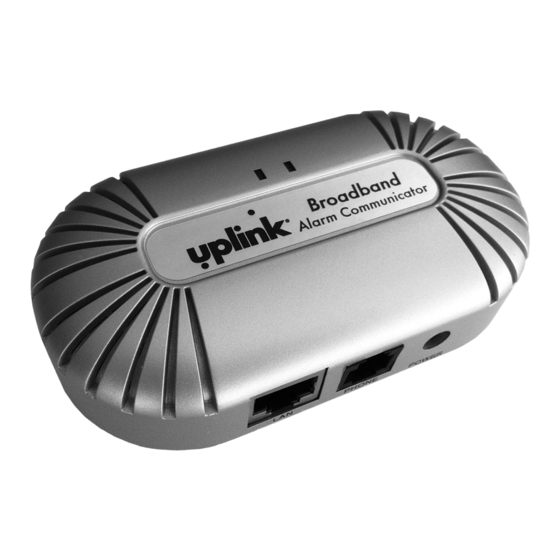
The 5200 converts the dialer output of an alarm system to an IP signal that can be transmitted securely over the internet to an Uplink server. A connection is then made to the central station to deliver the alarm signal. The 5200 supports two-way voice sessions as well as remote programming for most systems. -
Page 5: Installation
ALARM COMMUNICATOR INSTALLATION The physical installation of the Uplink 5200 is simple, but it is important to plan it beforehand. The unit requires power, a connection to the alarm panel, and a connection to the Internet. Choose a location where the 5200 can be connected to all of these things. -
Page 6: Connections Used
® 5200 CONNECTIONS USED LAN (RJ45 included) ....Connection to an internet router PHONE (RJ11) ......Connection to alarm system POWER ........Power adapter connection or 12V DC power 1. Connect one end of an RJ45 Ethernet cable to the “LAN” port of the 5200 and connect the other end to the Internet Router or Modem in the premises NOTE: THE 5200 MAY BE LOCATED BY THE ALARM SYSTEM OR BY THE ROUTER. -
Page 7: Activation
ALARM COMMUNICATOR ACTIVATION 1. Activate the unit on the Uplink Dealer Portal with the full ten digit unit serial number. The unit serial number begins with “B” and is found on the box label and device label. a. Enter the unit name and tracking number for your reference b. -
Page 8: Network Configuration
® 5200 NETWORK CONFIGURATION All settings in the 5200 can be changed by plugging a standard touchtone telephone into the PHONE port and using a simple voice prompt menu. To access the menu, follow these steps. Unplug your alarm system from the 5200 and plug in a touchtone telephone. The phone should connect to the PHONE port on the 5200. -
Page 9: Dialing The Alarm System For Touch-Tone Phone Remote Control & Upload And Download Over Dial Up Connection
BROADBAND ALARM COMMUNICATOR DIALING THE ALARM SYSTEM FOR TOUCH-TONE PHONE REMOTE CONTROL & UPLOAD AND DOWNLOAD OVER DIAL UP CONNECTION Dial-up touch-tone remote control of alarm systems is possible for most systems that support the function. To dial an alarm system connected to the 5200, dial 770-944-4601, wait for a second dial-tone, and dial the last nine digits of the 5200 unit/serial number. -
Page 10: Troubleshooting
® 5200 TROUBLESHOOTING Environments with VoIP phone service If the existing 5200 is connected directly to a single port cable or DSL modem, then disconnect it, and connect it to a router instead. The router should be the only device connected directly to the cable or DSL modem. If the customer’s VoIP phone service no longer works after doing this, then the VoIP provider will need to assist you or the customer in reconfiguring their device to work with a router. - Page 11 Wireless Ethernet bridges such as the Uplink 5300 can make installing the ® Uplink 5200 easy by eliminating the need to use an Ethernet cable. However, if WiFi signal is poor or the unit is not correctly set up, then they can cause many connection problems.
-
Page 12: Standard 12-Month Limited Warranty
Uplink. Uplink’s warranty does not extend to end user consumers of Uplink products or to other parties not in privity of contract with Uplink and, to the maximum extend permissible under applicable law, Uplink expressly disclaims any warranty, express or implied, extending to such end user consumer or parties including without limitations, any implied warranties or merchantability and fitness for a particular purpose. - Page 13 (cont.) IN NO EVENT SHALL UPLINK’S AGGREGATE LIABILITY TO ANY END USER CONSUMER OF AN UPLINK PRODUCT AND/OR SERVICE OR OTHER PARTY NOT IN PRIVITY OF CONTRACT WITH UPLINK ARISING OUT OF OR RELATED TO AN UPLINK PRODUCT AND/OR SERVICE, WHETHER ARISING OUT OF OR RELATED TO BREAK OF CONTRACT,...
-
Page 14: Fcc & Industry Canada Regulatory Compliance
® 5200 FCC & INDUSTRY CANADA REGULATORY COMPLIANCE Part 15 This device complies with Part 15 of the FCC Rules. Operation is subject to the following two conditions: (1) this device may not cause harmful interference, and (2) this device must accept any interference received, including interference that may cause undesired operation. -
Page 15: Fcc Rf Exposure Information
Technical support is available Monday through Friday, 8:00 AM to 8:00 PM ET ex- cluding holidays. Before calling technical support, please ensure you have read the installation guide completely. Technical support requires the caller to provide: Login name & password for the Uplink Dealer Portal Serial number of the 5200 UPLINK Security, LLC. -
Page 16: Technical Support
® FOR SALES, PRODUCT INFORMATION & TECHNICAL SUPPORT Uplink 3330 Cumberland Blvd. Suite 700 Atlanta, GA 30339 1-(888) 9-UPLINK, 1-(888)-987-5465 Fax 1-(888)-542-9105 sales@uplink.com www.uplink.com...


Need help?
Do you have a question about the L3-5200 and is the answer not in the manual?
Questions and answers