
Related Manuals for Uplink PRIMARY 2530


Summary of Contents for Uplink PRIMARY 2530
- Page 1 FOR SALES & PRODUCT INFORMATION Uplink 1600 Parkwood Circle Suite 500 Atlanta, GA 30339 1-(888) 9-UPLINK sales@uplink.com www.uplink.com FOR TECHNICAL SUPPORT Please visit our website at www.uplink.com.
- Page 2 MODEL 2530 PRIMARY CELLULAR COMMUNICATOR INSTALLATION & USER’S GUIDE PRODUCT ID # 19-25133-845...
- Page 3 The material in this manual is subject to change without notice. Uplink reserves the right to make changes to any software or product to improve reliability, function or design. Uplink is a trademark of Uplink Security, LLC. Other product names mentioned in this manual may be trademarks or registered trademarks of their respective companies and are hereby acknowledged.
-
Page 4: Table Of Contents
Table of Contents ........................1 Introduction ..........................2 Key Features ..........................3-5 Warranty Information & Liability Waiver ................6-8 TERMS and CONDITIONS ....................6 LIMITED WARRANTY – Uplink Devices ...............6 NO WARRANTY – SERVICES ...................7 INDEMNIFICATION ......................7 LIMITATIONS of LIABILITY ....................8 FCC and Regulatory Compliance & Part15 ..............9 FCC RF Exposure Information .....................10... -
Page 5: Introduction
The primary application for this unit is an instal- lation where no TELCO is present or available. The Uplink 2530 unit will “intercept” the alarm panel’s digital dialer output when the panel has an event to report, and communicate with the panel as if it were a central station alarm receiver. -
Page 6: Key Features
B. Panel to 2530 Cable Supervision. Monitors continuity of the cable connecting the panel’s telephone dialer to the 2530. This feature is activated through the website www.uplink.com or by calling Uplink Customer Service at 1-888-9-UPLINK (1-888-987- 5465). C. Output. The 2530 has one programmable relay output. This output can be... - Page 7 H. Easy Service Initiation. Ships with a SIM card, with easy activations available via the Web at www.uplink.com or by calling Uplink Customer Service at 1-888-9-UPLINK (1-888- 987-5465). Requires the central station receiver phone number and/or its IP address and Port number.
- Page 8 PRIMARY CELLULAR COMMUNICATOR The Model 2530 unit is ETL Recognized and conforms to UL Standards 985, 1023, and 1635 for Household Fire Warning, Household Burglar Alarm, and Digital Alarm Communicator systems. It is perfectly suited for use in any UL certificated household alarm systems that conform to the above standards.
-
Page 9: Warranty Information & Liability Waiver
12 months following the earlier of (a) the date of purchase or (b) the date of activation on Uplink’s network, and in no event longer than 12 months following the date of issuance,... -
Page 10: Warranty - Services
OF MERCHANTABILITY AND FITNESS FOR A PARTICULAR PURPOSE, TITLE, NON-INFRINGEMENT, AND NON-OBSOLESCENCE. THE FOREGOING WAR- RANTY FURTHERMORE DOES NOT COVER UPLINK DEVICES THAT (A) HAVE BEEN IMPROPERLY INSTALLED, MAINTAINED, OR SERVICED; (B) HAVE BEEN TAMPERED WITH OR DEFACED; OR (C) HAVE BEEN SUBJECTED TO ABUSE OR A HOSTILE OPERATING ENVIRONMENT. -
Page 11: Limitations Of Liability
MODEL 2530 WARRANTY INFORMATION AND LIABILITY WAIVER (cont.) LIMITATIONS of LIABILITY THE COMPANY SHALL NOT BE LIABLE FOR ANY ACTS OR OMISSIONS OF YOU, YOUR CUSTOMERS, END USERS OF THE PRODUCT, OR ANY THIRD PARTY INCLUDING, WITHOUT LIMITATION, ANY ENTITY FURNISHING EQUIPMENT, SOFTWARE, FIRMWARE, OR SERVICES TO THE COMPANY, YOU, YOUR CUSTOMERS, OR END USERS OF THE PRODUCT, NOR SHALL THE COMPANY BE LIABLE FOR ANY DAMAGES ATTRIBUTABLE, IN WHOLE OR IN... -
Page 12: Fcc And Regulatory Compliance & Part15
PRIMARY CELLULAR COMMUNICATOR FCC & REGULATORY COMPLIANCE Part 15 This device complies with Part 15 of the FCC Rules. Operation is subject to the following two conditions: (1) this device may not cause harmful interference, and (2) this device must accept any interference received, including interference that may cause undesired operation. -
Page 13: Fcc Rf Exposure Information
MODEL 2530 FCC RF EXPOSURE INFORMATION In August 1996 the Federal Communications Commission (FCC) of the United States with its action in Report and Order FCC 96-326 adopted an updated safety standard for human exposure to radio frequency electromagnetic energy emitted by FCC regulated transmitters. -
Page 14: Technical Support
Technical support requires the caller to provide: • Login name • Password • Serial number of the 2530 UPLINK Technical Support 1600 Parkwood Circle, Suite 500 Atlanta, GA 30339 888-9-Uplink (888-987-5465) Fax: 770-693-3501 For Customer Support, call 888-987-5465, or visit www.uplink.com. -
Page 15: Installation
MODEL 2530 INSTALLATION A. General Considerations Determine where to mount the unit. Keep the following in mind: a. Where to obtain the best transmitted and received signal strength for the cellular radio. (If the installer does not have a very strong cellular signal in his area, he may want to first power the unit from a portable 12V DC source, switch on S4 and move the unit to a location that gives him the best signal strength.) b. -
Page 16: Leds
PRIMARY CELLULAR COMMUNICATOR INSTALLATION (cont.) C. LEDs Normal Mode: Upon initial power up, the 5 LEDs on the 2530 will begin to function as follows: LED STATUS LED MEANING Power LED (#1) No DC power is present GREEN DC Power is present Flashing DC Input Voltage Low Panel Hook Status LED (#2) - Page 17 MODEL 2530 INSTALLATION (cont.) LED STATUS LED MEANING Heartbeat LED (#5) GREEN Flashing Unit is functioning normally Flashing S1 is ON after reset RSSI Mode: When the 2530 is placed in Received Signal Strength Indicator (RSSI) Mode by turning Dipswitch S4 to ON, the five LEDs indicate the follow signal strength information: RECEIVED SIGNAL STRENGTH APPEARANCE OF LEDs (#1 thru #5)
-
Page 18: Locating And Installing The 2530
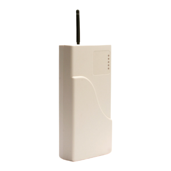
PRIMARY CELLULAR COMMUNICATOR INSTALLATION (cont.) D. Locating and Installing the 2530 The 2530 is housed in a plastic enclosure. The installer needs to supply DC power from the panel via the AUX output or via a separate DC power source. Input DC current is listed in Section 9 –... - Page 19 MODEL 2530 INSTALLATION (cont.) FIGURE 1: Model 2530 PC Board Details (INSTALLATION continued next page)
- Page 20 PRIMARY CELLULAR COMMUNICATOR INSTALLATION (cont.) 5. Position the bottom of the 2530 enclosure where it will be installed. Use four (4) #6 screws and mount the unit using the four holes in the enclosure’s plastic bottom. The 2530’s dimensions are shown in Figure 2. FIGURE 2: Inside &...
-
Page 21: Connecting The 2530 To The Alarm Panel
MODEL 2530 INSTALLATION (cont.) E. Connecting the 2530 to the Alarm Panel IMPORTANT: Make all of the connections to the 2530 in the powered down state. Once all of the connections have been established, turn power on. 1. First, remove DC input Power from the 2530, and then proceed as follows: 2. - Page 22 PRIMARY CELLULAR COMMUNICATOR INSTALLATION (cont.) FIGURE 3: Connections between the 2530 and the Alarm Panel (INSTALLATION continued next page)
-
Page 23: Activating The 2530 Unit
“Step 2. Rapid Signup – please provide Login & Contact Information. ” Fill out this form, then click Sign Up. f. Select the UPLINK DEALERS new/existing dealers button at the top of the page. Enter the Login Name and Password. Wait about 20 seconds for the next web page to completely load. - Page 24 Activation is complete one a successful test message is displayed. Existing Dealer 2530 Activation: For dealers/customers who already have an account with Uplink, go to the Uplink website (www.uplink.com). a. Enter the Login Name and Password. Wait about 20 seconds for the next web page to completely load.
-
Page 25: Programming And Central Station Reporting
MODEL 2530 INSTALLATION (cont.) G. Programming and Central Station Reporting Programming requires the telephone number of the monitoring central station’s alarm receiver and/or its IP address and Port number. Determine whether to use the default settings for the events to be reported or customize them by completing the following: Use this website to program: a. -
Page 26: Default Event/Email Messages
PRIMARY CELLULAR COMMUNICATOR INSTALLATION (cont.) 4. Normal State of Output Relay (Default = #1 Energized Closed) The normal state of the Output Relay can be changed from the Dealer website. 5. Definition of Output Relay (Default = #1 Loss of Cellular Service) There are 6 Trouble states that can be declared by the 2530, and each of these states can be programmed from the Dealer website to activate the Output Relay. -
Page 27: Completing The Installation And Testing
MODEL 2530 INSTALLATION (cont.) I. Completing the Installation and Testing Once the physical installation is completed, the unit is activated from the Dealer website, and programming changes are made, test the 2530 along with the alarm panel to ensure everything is functioning properly. Test the following: a. -
Page 28: Ul Compliance Section-Installation Recommendations
PRIMARY CELLULAR COMMUNICATOR UL COMPLIANCE SECTION– INSTALLATION RECOMMENDATIONS For installations that are intended to meet UL certification requirements, the following items must be adhered to during the installation for each stated certificate category. A. Household Fire (UL 985 - Category UTOU) 1. -
Page 29: Household Burglary (Ul 1023-Category Nbsx, And Evaluated To Ul 1635-Category Amcx)
MODEL 2530 UL COMPLIANCE SECTION– INSTALLATION RECOMMENDATIONS (cont.) B. Household Burglary (UL 1023-Category NBSX, and evaluated to UL 1635-Category AMCX) 1. The Model 2530 unit must be connected to an alarm panel that also holds a current UL 1023 Listing. 2. -
Page 30: Specifications
MODEL 2530 SPECIFICATIONS Panel to 2530 Interface Line Voltage 48 V DC On-Hook Dial tone 350 + 440 Hz +/- 0.2% Distortion All tones less than 2.0% DTMF twist accuracy +/- 1 dB Panel tones +/- 0.2% Receive level minimum - 45 dBm Receive S/N minimum 20 dB... - Page 31 PRIMARY CELLULAR COMMUNICATOR SPECIFICATIONS (cont.) Radio Frequencies 850/900/1800/1900 MHz DC Voltage 3.3 - 4.5 V DC Sensitivity -106 dB (typical) Environmental Temperature Range -30° to +70° C Humidity 0 to 95% non-condensing Physical Height 2.5 inches Width 5.4 inches Depth 10.5 inches...
- Page 32 MODEL 2530 APPENDIX A: CONTACT ID, SIA EVENT, AND MODEM IIe/IIIa/IIIa CODES Following is a list of event codes that can be sent to the central station receiver for events generated by the 2530: EVENT DESCRIPTION CONTACT ID SIA DC-03 MODEM lle/llla/ EVENT CODE EVENT CODE...
- Page 33 PRIMARY CELLULAR COMMUNICATOR APPENDIX A: CONTACT ID, SIA EVENT, AND MODEM IIe/IIa/IIIa CODES (cont.) EVENT DESCRIPTION CONTACT ID SIA DC-03 MODEM lle/llla/ EVENT CODE EVENT CODE llla Low Temperature Restoral R159 Medical Alarm E100 Medical Restoral R100 Opening E400 Panic Alarm E120 Panic Restoral R120...
-
Page 34: Event Codes
MODEL 2530 APPENDIX B: 2530 DEFAULT EVENT CODES The 2530 is defaulted to send both the Alarm/Trouble condition and the Restoral condition for all of the events listed below. Reporting of individual events can be controlled from the Dealer website. Following is a list of the default event codes sent by the 2530: MODEM IIe/ EVENT DESCRIPTION... - Page 35 PRIMARY CELLULAR COMMUNICATOR UPLINK 2530 PRIMARY CELLULAR COMMUNICATOR INSTALLATION, OPERATION AND PROGRAMMING GUIDE DATED 03/07/11 ©2011 UPLINK SECURITY, LLC GUIDE 00-25580-845 REV E 1600 PARKWOOD CIRCLE, SUITE 500, ATLANTA, GA 30339 888-987-5465 (888-9-UPLINK) WWW.UPLINK.COM...
Need help?
Do you have a question about the PRIMARY 2530 and is the answer not in the manual?
Questions and answers