Table of Contents
Advertisement
Quick Links
Printed Matter No. 9839 1309 01
Publication Date 2020-02-13
Valid from Serial No. A0540001
Valid to Serial No. A2419999
PFD1100IL-CCI010B (520 r/min)
Read all safety warnings and instructions
Failure to follow the safety warnings and instructions may result in
electric shock, fire and/or serious injury.
Save all warnings and instructions for future reference
PFD1100IL-CCI010B
8440112036
WARNING
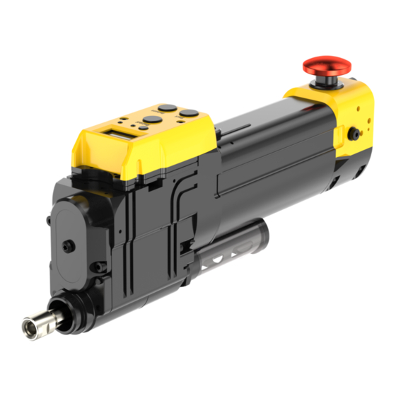
Positive feed drill
Product Instructions
Advertisement
Table of Contents

Related Manuals for Atlas Copco PFD1100IL-CCI010B


Summary of Contents for Atlas Copco PFD1100IL-CCI010B
- Page 1 Positive feed drill Publication Date 2020-02-13 Valid from Serial No. A0540001 Product Instructions Valid to Serial No. A2419999 PFD1100IL-CCI010B (520 r/min) 8440112036 WARNING Read all safety warnings and instructions Failure to follow the safety warnings and instructions may result in electric shock, fire and/or serious injury.
-
Page 2: Table Of Contents
Assembling swiveling front part ............ 37 Assembling HD indexer kit .............. 38 Operation ....................... 40 Ergonomic guidelines .................. 40 Configuration instructions ................ 40 Replacing components ................ 40 Changing the speed ................ 41 Changing the feed rate ................ 43 Operating instructions.................. 43 © Atlas Copco Industrial Technique AB - 9839 1309 01... - Page 3 Housing, upper .................. 52 Spindle.................... 53 Split gear ..................... 53 Housing, lower.................. 53 Feed cassette .................. 54 Test after service .................... 55 Troubleshooting.................... 56 Troubleshooting overview................ 56 Recycling ....................... 59 Recycling instruction.................. 59 Recycling information for PFD1100IL (without inboard pump) ....... 59 © Atlas Copco Industrial Technique AB - 9839 1309 01...
-
Page 4: Product Information
■ Damage to parts that occurs as a result of inadequate maintenance or performed by parties other than Atlas Copco or their Certified Service Partners during the warranty period is not covered by the warranty. ■ To avoid damage or destruction of tool parts, service the tool according to the recommended mainte- nance schedules and follow the correct instructions. -
Page 5: Servaid
ServAid is continuously updated and is available at: https://servaid.atlascopco.com For further information contact your local Atlas Copco representative. Safety Data Sheets MSDS/SDS The safety data sheets describes chemical products sold by Atlas Copco. For more information, consult the website: www.atlascopco.com/sds Country of origin Please refer to the information on the product label. -
Page 6: Main Components And Functions
The motor continues to run after the button is released. When the spindle reaches the pre-defined drilling depth, it returns automati- cally to the starting position and the motor switches off. © Atlas Copco Industrial Technique AB - 9839 1309 01... -
Page 7: Technical Data
108.8 psig Minimum working pressure 5.5 bar Minimum working pressure 79.8 psig Rapid advance Recommended hose size 16 mm Recommended hose size 5/8 in Sound pressure 76 dB(A) Sound standard ISO15744 © Atlas Copco Industrial Technique AB - 9839 1309 01... -
Page 8: Accessories
Product information PFD1100IL-CCI010B Sound uncertainty 3 dB(A) Thrust 2000 N Thrust 450 lbf Weight 3 kg Weight 6.6 lb Width 130 mm Width 5.11 in Accessories Overview accessories © Atlas Copco Industrial Technique AB - 9839 1309 01... - Page 9 4141 0653 91 245 mm (9.7") 9/16" Spindle 4141 0653 92 219 mm (8.6") 9/16" Spindle 4141 0653 93 296 mm (11.7”) 9/16" Spindle 4141 0869 94 245 mm (9") 7/16" © Atlas Copco Industrial Technique AB - 9839 1309 01...
- Page 10 127 mm (5") 3/4"-16 UNF Cannot be used with Scraper nut Front part 4141 0886 90 127 mm (5") 3/4"-16 UNF Can be used with Scraper nut 4141 0884 90. © Atlas Copco Industrial Technique AB - 9839 1309 01...
- Page 11 4141 0250 95 4141 0251 91 Vacuum attachment 4141 0250 96 4141 0251 92 Vacuum attachment 4141 0250 97 4141 0245 91 Vacuum attachment 4141 0250 98 4141 0257 90 © Atlas Copco Industrial Technique AB - 9839 1309 01...
- Page 12 Ød 11.5 mm. Order together with 4141 0813 12. Suitable for concentric collet MINI and REGULAR. Mandrel 4141 0806 13 Ød 11.9 mm. Order together with 4141 0813 13. Suitable for concentric collet MINI and REGULAR. © Atlas Copco Industrial Technique AB - 9839 1309 01...
- Page 13 Ød 24.25 mm. Order together with 4141 0814 16. Suitable for concentric collet HD. Mandrel 4141 0810 05 Ød 26.65 mm. Order together with 4141 0814 24. Suitable for concentric collet HD. © Atlas Copco Industrial Technique AB - 9839 1309 01...
- Page 14 ØD 23 mm. Order together with 4141 0806 22. Suitable for concentric collet MINI and REGULAR. Collet 4141 0813 23 ØD 23.4 mm. Order together with 4141 0806 23. Suitable for concentric collet MINI and REGULAR. © Atlas Copco Industrial Technique AB - 9839 1309 01...
- Page 15 Max stroke 62 mm, spacer length 40 mm. Suitable for concentric collet MINI and REGULAR. Guide bushing 4141 0707 96 Max stroke 73 mm, spacer length 50 mm. Suitable for concentric collet MINI and REGULAR. © Atlas Copco Industrial Technique AB - 9839 1309 01...
- Page 16 4141 0434 92 Non-inboard lubrication tools Starting position and drilling depth Using stop rings, you can define the following parameters: ■ Starting position of the drill bit ■ Drilling depth © Atlas Copco Industrial Technique AB - 9839 1309 01...
- Page 17 NOTE: If the starting position ring is not used, the motor switches off when the lowest part of the spindle reaches the disc spring at home position. Depth ring Defines the drilling depth. © Atlas Copco Industrial Technique AB - 9839 1309 01...
-
Page 18: Speed
Markings on the split gear housing indicate ratios. The markings, on the split gear housing closest to the motor housing of the drill, indicate the actual ratio. See the figure below. © Atlas Copco Industrial Technique AB - 9839 1309 01... -
Page 19: Feed Rate
The feed rate of the drill must be balanced with the spindle speed. Select from the available combinations of feed rates in the table below to get the de- sired feed rate. © Atlas Copco Industrial Technique AB - 9839 1309 01... -
Page 20: Counter
4141 0428 94 0.0045 0.115 4141 0428 93 0.0052 0.13 4141 0428 97 0.0059 0.15 4141 0428 96 0.0064 0.16 4141 0428 91 0.0068 0.17 4141 0428 95 Counter Overview © Atlas Copco Industrial Technique AB - 9839 1309 01... - Page 21 ADU. BATTERY VOLTAGE The percentage of the battery that is left. Minimum 1.9 V. Changing setting and value © Atlas Copco Industrial Technique AB - 9839 1309 01...
- Page 22 Programs value VAL TOOL MX for CNT TOOL. PRG SERV Programs value VAL TOOL MX for CNT SERV. PRG DLY Programs DRL DLAY. REPL BAT Safeguards the counter before battery replacement. © Atlas Copco Industrial Technique AB - 9839 1309 01...
- Page 23 Product information Flowchart of how the counter works. Alarm The following alarms can be seen on the counter LEDs, red-yellow and green. Green Yellow Signification of alarms Flash Drilling detected. © Atlas Copco Industrial Technique AB - 9839 1309 01...
- Page 24 Make sure the cable is not squeezed. Put the air logic cover back into original position and tighten the cover with the screws using an Allen key. Press the button SW-L to begin using the counter. © Atlas Copco Industrial Technique AB - 9839 1309 01...
-
Page 25: Service Overview
If no detailed information about preventive maintenance is included, follow these general guidelines: ■ Clean appropriate parts accurately ■ Replace any defective or worn parts Maintenance intervals One cycle is calculated on a standard stack of 10 mm. © Atlas Copco Industrial Technique AB - 9839 1309 01... - Page 26 ■ 10 < Drill bit <12,7 Drill bit: <10mm Drill bit: <12,7mm mm (<1/2") (<3/8") (<1/2") Material: Titan Material: Titan Material: CFRP ■ Drill bit > 12,7mm (>1/2") Material: CF © Atlas Copco Industrial Technique AB - 9839 1309 01...
-
Page 27: Installation
We recommend to use the tool with oil-free air. In case you need to use lubricated air, we strongly recom- mend that you install an Atlas Copco oil-fog lubricator (DIM). This should be set with maximum of 20 drops per min (1 drop = 15 mm ). -
Page 28: Installation Instructions
Push the emergency stop button so that it locks in position. The air supply to the motor switches off and the spindle stops. Disconnect the air hose. Pull the emergency stop button to reset it. © Atlas Copco Industrial Technique AB - 9839 1309 01... - Page 29 PFD1100IL-CCI010B Installation © Atlas Copco Industrial Technique AB - 9839 1309 01...
-
Page 30: Changing The Spindle
Turn the spindle clockwise to remove it using an open-end spanner. If applicable, remove the starting position ring using an Allen key. Do steps 2 to 7 in the section “Installing the drill”. © Atlas Copco Industrial Technique AB - 9839 1309 01... -
Page 31: Installing The Indexing Stop Nut
Note that there are 4 metal lugs inside the nut. These lugs need to be eased into the 4 corre- sponding grooves on the spindle when attaching the nut. © Atlas Copco Industrial Technique AB - 9839 1309 01... -
Page 32: Installing The Concentric Collet
13. Put the collet over the mandrel. If the collet is put in correct position, the flanges on the collet will now fit into the slots on the mandrel and prevent it from turning. Install the cap nut on the concentric collet. Tighten it using a hook wrench. © Atlas Copco Industrial Technique AB - 9839 1309 01... - Page 33 PFD1100IL-CCI010B Installation © Atlas Copco Industrial Technique AB - 9839 1309 01...
-
Page 34: Installing The Chiplet
Put the ratchet back in original position. Put the cover in front of the ratchet and tighten the cover with the screw. Do steps 5 to 7 in the section “Installing the drill”. © Atlas Copco Industrial Technique AB - 9839 1309 01... - Page 35 PFD1100IL-CCI010B Installation © Atlas Copco Industrial Technique AB - 9839 1309 01...
-
Page 36: Calibrating The Position Of The Indexing Stop Nut
When making the final adjustments, the upper nut should be tightened lightly by hand. For each ad- justment of 0.02 mm, a "click" is felt when turning the lower nut. When the position is correct, tighten the upper locking nut using an open-end spanner. © Atlas Copco Industrial Technique AB - 9839 1309 01... -
Page 37: Installing The Indexer
For the parts that use regular indexer: Remove the locking washer from the front part. Slide the vacuum attachment onto the front part. Attach the locking washer back to the groove on the front part. © Atlas Copco Industrial Technique AB - 9839 1309 01... -
Page 38: Assembling Hd Indexer Kit
Put the nut into the indexer housing, with the threads downwards. Tighten the nut with the indexer in- stalling tool. Put the waved washer and the shaft. With the splines downwards, into the indexer housing. © Atlas Copco Industrial Technique AB - 9839 1309 01... - Page 39 Push the button on the indexer housing, so the nut easily moves down to the bottom. Tighten the front nut on the shaft onto the indexer housing with an open-end spanner. © Atlas Copco Industrial Technique AB - 9839 1309 01...
-
Page 40: Operation
Use ear protection equipment in noisy environments. ■ Use dust extraction system or mouth protection mask in dusty environments. Configuration instructions Replacing components Component Head Feed cassette Air logic Split gear © Atlas Copco Industrial Technique AB - 9839 1309 01... -
Page 41: Changing The Speed
Only for a high-speed drill: Put the spline connection back into position. 12. Put the motor housing back into original position. 13. Put the motor valve back into original position and secure it with screws using an Allen key. © Atlas Copco Industrial Technique AB - 9839 1309 01... - Page 42 Operation PFD1100IL-CCI010B © Atlas Copco Industrial Technique AB - 9839 1309 01...
-
Page 43: Changing The Feed Rate
Make sure that the lock pin is flush to the nut surface with a tolerance level of less than 0.3mm ► above the surface. © Atlas Copco Industrial Technique AB - 9839 1309 01... - Page 44 Release the button to lock in position. Check that the lock pin on the indexer is level to the nut surface. Rock the tool from side to side to confirm the tool being locked in position. © Atlas Copco Industrial Technique AB - 9839 1309 01...
-
Page 45: Releasing Concentric Collet Without Air Pressure
Put the release tool in position and fasten it. Turn the knob clockwise until the concentric collet releases. Remove the drill from the fixture. Remove the release tool and install the screw. © Atlas Copco Industrial Technique AB - 9839 1309 01... -
Page 46: Unlocking And Locking Indexer
To unlock indexer, press and hold the button (A) or the Release button (B) and rotate the indexer shaft. To lock indexer, rotate the indexer shaft until a "click" is felt and the safety button retracts. © Atlas Copco Industrial Technique AB - 9839 1309 01... -
Page 47: Operating The Drill
To reset the emergency stop and restore normal oper- disconnect the air hose. Pull the emergency stop but- ation... ton, reconnect the air hose to reset the air logic. © Atlas Copco Industrial Technique AB - 9839 1309 01... -
Page 48: Service
4081 0496 90 Planetary shaft Grease (Type A) Grease (Type A) grease (LS tool) Overload clutch Grease (Type A) Grease (Type A) Grease (Type A) Independent from the drilling thickness © Atlas Copco Industrial Technique AB - 9839 1309 01... -
Page 49: Lubrication Instructions
Lubrication guide Valid lubricants: Lubricant Description Klübersynth PEG 46-121 (Ordering No. 4081 0487 90). Rehnus LKR 03 (Ordering No. 4081 0487 91). © Atlas Copco Industrial Technique AB - 9839 1309 01... -
Page 50: Motor Housing
Apply a thin layer of lubricant A. Fill lubricant A between needle bearings. Fill gap with 7 ml of lubricant B. Do not apply lubricant. Motor valve Total amount of lubricant: Approximately 2 ml. © Atlas Copco Industrial Technique AB - 9839 1309 01... -
Page 51: Housing Bevel Gear
PFD1100IL-CCI010B Service Description Apply a thin layer of lubricant A or B. Do not apply lubricant. Housing bevel gear Description Do not apply lubricant. © Atlas Copco Industrial Technique AB - 9839 1309 01... -
Page 52: Housing, Upper
Apply a thin layer of lubricant A or B. Fill gap with 3 ml of lubricant A. Apply a thin layer of lubricant A. Fill lubricant A between needle bearings. Do not apply lubricant. © Atlas Copco Industrial Technique AB - 9839 1309 01... -
Page 53: Spindle
Apply a thin layer of lubricant A or B. Fill lubricant A between needle bearings. Fill gap completely with lubricant B. Housing, lower Total amount of lubricant: Approximately 5 ml. © Atlas Copco Industrial Technique AB - 9839 1309 01... -
Page 54: Feed Cassette
Fill lubricant A between needle bearings. Do not apply lubricant. Feed cassette Total amount of lubricant A: Approximately 3 ml. Description Ensure that all cog gaps are filled with lubricant A. Do not apply lubricant. © Atlas Copco Industrial Technique AB - 9839 1309 01... -
Page 55: Test After Service
Push the retract button, wait for the tool to stop in home position and push the release button and hold it down. Make sure that: ■ Remove the collet from bushing. Test after service is now finished. © Atlas Copco Industrial Technique AB - 9839 1309 01... -
Page 56: Troubleshooting
3) Remove the bevel gears from bevel gear housing. 4) Make sure the bevel gears con- dition are OK. If the bevel gears are OK, the gear wheels in the head are broken. © Atlas Copco Industrial Technique AB - 9839 1309 01... - Page 57 Emergency stop activated. Pull the emergency stop button to reset it. Air leak in valve pins in upper Make sure no air leaks exists. housing. Motor valve defective. Replace the motor valve. © Atlas Copco Industrial Technique AB - 9839 1309 01...
- Page 58 Replace the overload clutch. Tool starts but retract when start Air leak in overload clutch. Replace the overload clutch. button is released. © Atlas Copco Industrial Technique AB - 9839 1309 01...
-
Page 59: Recycling
Air logic cover Metal, Aluminum Motor Metal, Aluminum Motor valve Metal, Aluminum Counter Electronic Spindle Metal, Steel Head Metal, Aluminum Split gear Metal, Steel Cover Metal, Aluminum Motor housing Metal, Aluminum © Atlas Copco Industrial Technique AB - 9839 1309 01... - Page 60 Original instructions © Copyright 2020, Atlas Copco Industrial Technique AB. All rights reserved. Any unauthorized use or copying of the contents or part thereof is prohibited. Atlas Copco Industrial This applies in particular to trademarks, model denominations, part numbers Technique AB and drawings.
Need help?
Do you have a question about the PFD1100IL-CCI010B and is the answer not in the manual?
Questions and answers