Table of Contents
Advertisement
Quick Links
Printed Matter No. 9836 6024 01
Publication Date 2020-02-11
Valid from Serial No. B2420001
PFD1500RA-180 (180 r/min)
Read all safety warnings and instructions
Failure to follow the safety warnings and instructions may result in
electric shock, fire and/or serious injury.
Save all warnings and instructions for future reference
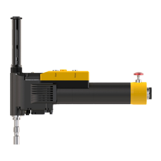
PFD1500RA-180
8440150002
WARNING
Positive feed drill
Product Instructions
Advertisement
Table of Contents

Related Manuals for Atlas Copco PFD1500RA-180


Summary of Contents for Atlas Copco PFD1500RA-180
- Page 1 Printed Matter No. 9836 6024 01 Positive feed drill Publication Date 2020-02-11 Valid from Serial No. B2420001 Product Instructions PFD1500RA-180 (180 r/min) 8440150002 WARNING Read all safety warnings and instructions Failure to follow the safety warnings and instructions may result in electric shock, fire and/or serious injury.
-
Page 2: Table Of Contents
Installing the scraper kit, for drills without indexer ....... 28 Preparation for the spindles 4141 0253 XX......... 29 Operation ....................... 31 Ergonomic guidelines .................. 31 Configuration Instructions ................ 31 Replacing modules ................ 31 Changing the speed ................ 32 Changing the feed rate ................ 33 Operating Instructions.................. 34 © Atlas Copco Industrial Technique AB - 9836 6024 01... - Page 3 Dismantling/Assembling Instructions .............. 49 Instructions for vane motor .............. 49 Instructions for vane motor .............. 51 Assembling Indexer ................ 53 Troubleshooting.................... 54 Troubleshooting overview................ 54 Test of overload clutch.................. 55 Leak test ...................... 56 Recycling ....................... 57 Environmental Regulations................ 57 © Atlas Copco Industrial Technique AB - 9836 6024 01...
-
Page 4: Product Information
■ Damage to parts that occurs as a result of inadequate maintenance or performed by parties other than Atlas Copco or their Certified Service Partners during the warranty period is not covered by the warranty. ■ To avoid damage or destruction of tool parts, service the tool according to the recommended mainte- nance schedules and follow the correct instructions. -
Page 5: Servaid
For further Technical Information, please contact your local Atlas Copco representative. Safety Data Sheets MSDS/SDS The Safety Data Sheets describe the chemical products sold by Atlas Copco. Please consult the Atlas Copco website for more information www.atlascopco.com/sds. Country of Origin For the Country of Origin, please refer to the information on the product label. -
Page 6: Main Components And Functions
(RPM). Range gear Defines RPM range. Vane motor Supplies power and rotation to the spindle. Motor valve Supplies the airflow to the vane mo- tor and the emergency stop button. © Atlas Copco Industrial Technique AB - 9836 6024 01... -
Page 7: Technical Product Data
You must manually reset the emergency stop to restart the drill. Technical Product Data Technical Product Data can be found on either ServAid, or the Atlas Copco website. Please visit: https://servaid.atlascopco.com or www.atlascopco.com. - Page 8 You can calculate the distance between the depth ring and the drill head (dimension L in the figure below) for the desired drill depth D according to the following formula: L (mm) =D (mm) – 31.0 mm L (in) = D (in) – 1.2 in © Atlas Copco Industrial Technique AB - 9836 6024 01...
-
Page 9: Speed
(2), see the figure below. Markings on the split gear housing indicate ratios corresponding to shaft positions. Secure that the shaft is in the right position with the fork-shaped tool (4141 1114 00). See the figure be- low. © Atlas Copco Industrial Technique AB - 9836 6024 01... -
Page 10: Velocity Rapid Advance - Pfd1500Ra-R (Only For Models With Rapid Advance)
0.10 PFD1500RA-100-R 0.15 PFD1500RA-140-R 0.20 PFD1500RA-180-R 0.26 PFD1500RA-200-R 0.29 PFD1500RA-270-R 10.0 0.39 PFD1500RA-360-R 13.3 0.52 PFD1500RA-400-R 14.8 0.58 PFD1500RA-530-R 19.7 0.78 PFD1500RA-670-R 24.8 0.98 PFD1500RA-700-R 25.9 1.02 PFD1500RA-900-R 33.3 1.31 © Atlas Copco Industrial Technique AB - 9836 6024 01... -
Page 11: Feed Rate
If the product is not working properly, take it out of service and inspect it. If no detailed information about preventive maintenance is included, follow these general guide- lines: ■ Clean appropriate parts accurately ■ Replace any defective or worn parts © Atlas Copco Industrial Technique AB - 9836 6024 01... -
Page 12: Installation
Poor air quality may cause damage to the tool and reduce the performance. ■ For optimum performance and maximum product life we recommend the use of compressed air with a maximum dew point of -5°C (23°F). We also recommend to install an Atlas Copco refrigeration type air dryer. ■... - Page 13 Put the front part over the drill and secure it. © Atlas Copco Industrial Technique AB - 9836 6024 01...
- Page 14 Push the emergency stop button so that it locks in position. The spindle must stop immediately. Pull the emergency stop button to reset it. The motor must not restart. Disconnect the air hose. © Atlas Copco Industrial Technique AB - 9836 6024 01...
- Page 15 PFD1500RA-180 Installation © Atlas Copco Industrial Technique AB - 9836 6024 01...
- Page 16 Installation PFD1500RA-180 © Atlas Copco Industrial Technique AB - 9836 6024 01...
-
Page 17: Changing The Spindle
Remove the feed cassette. Feed the spindle out of the socket by turning a hexagonal tool counterclockwise. Remove the spin- dle. Perform the steps 4 to 11 in the section “installing the drill”. © Atlas Copco Industrial Technique AB - 9836 6024 01... - Page 18 Push the emergency stop button so that it locks in position. The spindle must stop immediately. Pull the emergency stop button to reset it. The motor must not restart. Disconnect the air hose. © Atlas Copco Industrial Technique AB - 9836 6024 01...
-
Page 19: Installing The Scraper Kit, For Drills With Indexer
Tighten the nut. Put the wave washer in position on the indexer housing. Apply a few drops of thread locker on the shaft and attach it to the indexer housing. © Atlas Copco Industrial Technique AB - 9836 6024 01... - Page 20 The scraper ring on the spindle shall not move outside the tube when drilling. 13. Install the tube and tighten it. Make sure that the scraper ring runs smoothly to prevent thread damage. Install the front part. © Atlas Copco Industrial Technique AB - 9836 6024 01...
-
Page 21: Installing The Drill
Fasten the drill in a vise with rubber pads, with the air logic unit upward and the drill handle to the right. Note the position of the feed cassette. The markings, on the cassette end closest to the spindle, indi- cate the actual feed rate. © Atlas Copco Industrial Technique AB - 9836 6024 01... - Page 22 Push the emergency stop button so that it locks in position. The spindle must stop immediately. Pull the emergency stop button to reset it. The motor must not restart. Disconnect the air hose. © Atlas Copco Industrial Technique AB - 9836 6024 01...
-
Page 23: Installing The Indexer
WARNING Make sure that the air supply is not connected. CAUTION Wear gloves to avoid personal injury because of sharp cutting edges. Only experi- enced maintenance personnel can assemble or disassemble the product. © Atlas Copco Industrial Technique AB - 9836 6024 01... - Page 24 Make sure that the lock pin is flush to the nut surface with a tolerance level of less than ► 0.3mm above the surface. Install the components in the list above after finishing the installation. © Atlas Copco Industrial Technique AB - 9836 6024 01...
-
Page 25: Installing The Chiplet
10. Put the feed cassette back in position and fasten the four screws and two washers to 8 Nm. 11. Put the cassette cover back in position on the cassette and fasten it with one screw to 3 Nm. © Atlas Copco Industrial Technique AB - 9836 6024 01... - Page 26 Installation PFD1500RA-180 © Atlas Copco Industrial Technique AB - 9836 6024 01...
-
Page 27: Changing The Air Inlet Adapter
Replace the adapter with the new one (included in the box). Move the o-ring from the old adapter to the new one. Put the adapter back in original position. Tighten the adapter. Make sure that the filter is in position. © Atlas Copco Industrial Technique AB - 9836 6024 01... -
Page 28: Installing The Scraper Kit, For Drills Without Indexer
The scraper ring on the spindle shall not move outside the tube when drilling. Install the tube and fasten it to 20 Nm. Make sure that the scraper ring runs smoothly to prevent thread damage. Install the front part. © Atlas Copco Industrial Technique AB - 9836 6024 01... -
Page 29: Preparation For The Spindles 4141 0253 Xx
PFD1500RA-180 Installation Preparation for the spindles 4141 0253 XX Using this spindle, you can define your own thread size. © Atlas Copco Industrial Technique AB - 9836 6024 01... - Page 30 Clamp the collet chuck over the spindle thread. The thread should not stick out more than (L1). See figure below. Note the dimension of the drilling depth (L2) and the thread size (L3). See figure below. © Atlas Copco Industrial Technique AB - 9836 6024 01...
-
Page 31: Operation
Use ear protection equipment in noisy environments. ■ Use dust extraction system or mouth protection mask in dusty environments. Configuration Instructions Replacing modules You can easily replace all drill modules: Module Head Feed cassette Air logic © Atlas Copco Industrial Technique AB - 9836 6024 01... -
Page 32: Changing The Speed
Push the emergency stop so that it locks in position. The spindle must stop immediately. Pull the emergency stop button to reset it. The motor must not restart. Disconnect the air hose. Reconnect the air hose. © Atlas Copco Industrial Technique AB - 9836 6024 01... -
Page 33: Changing The Feed Rate
Push the emergency stop button so that it locks in position. The air supply to the motor switches off and the spindle stops. Disconnect the air hose. Pull the emergency stop button to reset it. Reconnect the air hose. © Atlas Copco Industrial Technique AB - 9836 6024 01... -
Page 34: Operating Instructions
Release the button on the indexer to lock in position. Check that the lock pin on the indexer is level to the nut surface. Rock the tool from side to side to confirm the tool being locked in position. © Atlas Copco Industrial Technique AB - 9836 6024 01... -
Page 35: Operating The Drill
To reset the emergency stop and restore normal oper- pull the emergency stop button. Disconnect the air ation... hose, and then reconnect it to reset the air logic. © Atlas Copco Industrial Technique AB - 9836 6024 01... -
Page 36: Service
4141 0063 90 4141 0012 91 , 4141 0012 , 4141 0019 91 Every 12000 drilled holes 4081 0452 90, 4081 0453 90, 4081 0454 90 , 4081 0455 90 © Atlas Copco Industrial Technique AB - 9836 6024 01... - Page 37 <1 1/4" Titan/Alu Cycles (Use kit, Ordering No.) (Use kit, Ordering No.) (Use kit, Ordering No.) Every 1000 drilled holes Every 3000 drilled holes Every 6000 drilled holes Every 12000 drilled holes © Atlas Copco Industrial Technique AB - 9836 6024 01...
- Page 38 4141 0034 91, 4141 0034 4141 0034 93, 4141 0034 4141 0034 95, 4141 0034 * Please order the correct kit for your specific feed cassette, see spare part list. © Atlas Copco Industrial Technique AB - 9836 6024 01...
-
Page 39: Lubrication Instructions
Klübersynth PEG 46-121. Can filled with 1 KG grease, (Ordering No. 4081 0487 90). Vane motor oil (Q8 Chopin S46) All O-rings shall be greased before assembly with lubricant A or B (thin layer). © Atlas Copco Industrial Technique AB - 9836 6024 01... -
Page 40: Motor Valve
Apply a thin layer of lubricant A. Range gear Total amount of lubrication: 15 ml. Turn gear while lubricating at least two turns. Ensure that gear is running normally without hacking. © Atlas Copco Industrial Technique AB - 9836 6024 01... -
Page 41: Indexer 4141 0912 90
Indexer 4141 0912 90 Description Apply a thin layer of lubricant A. Ensure that the O-rings are well greased with lubricant Ensure that all cog gaps are well filled with lubricant A. © Atlas Copco Industrial Technique AB - 9836 6024 01... -
Page 42: Range Gear
Description Ensure that the radial seals are filled with lubricant A before assembly, also lubricate the outside and sliding surfaces. Ensure that needle bearings are completely filled with lubricant A. © Atlas Copco Industrial Technique AB - 9836 6024 01... -
Page 43: Indexer 4141 0306 91
Indexer 4141 0306 91 Description Apply a thin layer of lubricant A. Ensure that the O-rings are well greased with lubricant Ensure that all cog gaps are well filled with lubricant A. © Atlas Copco Industrial Technique AB - 9836 6024 01... -
Page 44: Head
Ensure that all cog gaps are well filled with lubricant A. Fill inner trapezoidal thread with lubricant A. Ensure that all cog gaps are well filled with lubricant A (5 ml per part). © Atlas Copco Industrial Technique AB - 9836 6024 01... - Page 45 Apply minimum 10 ml of lubricant A. * Only for models with rapid advance. Description Ensure that all cog gaps are well filled with lubricant A (5 ml per part). © Atlas Copco Industrial Technique AB - 9836 6024 01...
-
Page 46: Motor
WARNING Make sure that the air supply is not connected. CAUTION Wear gloves to avoid personal injury because of sharp cutting edges. Only experi- enced maintenance personnel can assemble or disassemble the product. © Atlas Copco Industrial Technique AB - 9836 6024 01... - Page 47 Step 1 – Make a visible test. Remove the valves from the tool. Turn the valves clockwise with the fork-shaped tool. Compress the valves and see if the spring is OK. Step 2 – See section “Leak test”. © Atlas Copco Industrial Technique AB - 9836 6024 01...
- Page 48 Service PFD1500RA-180 © Atlas Copco Industrial Technique AB - 9836 6024 01...
-
Page 49: Dismantling/Assembling Instructions
4080 0182 07 12.5 4080 0182 08 15.5 4080 0182 09 17.5 4080 0182 10 20.5 4080 0182 11 25.5 4080 0182 12 30.5 4080 0182 13 35.5 4080 0182 14 40.5 © Atlas Copco Industrial Technique AB - 9836 6024 01... - Page 50 4080 0567 02 18.5 4080 0567 06 21.5 4080 0567 03 21.5 4080 0567 07 25.5 10.5 4080 0567 08 27.5 12.5 4080 0567 09 31.5 15.5 4080 0567 10 34.5 18.5 © Atlas Copco Industrial Technique AB - 9836 6024 01...
- Page 51 4080 0182 07 12.5 4080 0182 08 15.5 4080 0182 09 17.5 4080 0182 10 20.5 4080 0182 11 25.5 4080 0182 12 30.5 4080 0182 13 35.5 4080 0182 14 40.5 © Atlas Copco Industrial Technique AB - 9836 6024 01...
- Page 52 4080 0567 02 18.5 4080 0567 06 21.5 4080 0567 03 21.5 4080 0567 07 25.5 10.5 4080 0567 08 27.5 12.5 4080 0567 09 31.5 15.5 4080 0567 10 34.5 18.5 © Atlas Copco Industrial Technique AB - 9836 6024 01...
-
Page 53: Assembling Indexer
As the indexer is parted, push the button to ensure that the lock pin on the indexer runs smoothly in and out of the housing. Replace the part or complete indexer if there is any damage to the indexer's part. © Atlas Copco Industrial Technique AB - 9836 6024 01... -
Page 54: Troubleshooting
2. Do a leak test of the valve, see the section “Leak test”. 3. If the results of the test are un- satisfactory, replace the valve. Oth- erwise, contact Atlas Copco ser- vice center. © Atlas Copco Industrial Technique AB - 9836 6024 01... -
Page 55: Test Of Overload Clutch
Attach the clutch to the connector (3) and put the hexagonal tool on the clutch. See the figure below. Tighten the clutch counterclockwise to 10 Nm ±2 Nm. If the clutch operates correctly, it releases with a loud click within the specified torque range. © Atlas Copco Industrial Technique AB - 9836 6024 01... -
Page 56: Leak Test
If the result of the test is unsatisfactory, replace the valve. If the test shows no fault, continue the pro- cedure. Install the valve in the original position and tighten it with the fork-shaped tool to 0.7 Nm. © Atlas Copco Industrial Technique AB - 9836 6024 01... -
Page 57: Recycling
When a product has served its purpose it has to be recycled properly. Dismantle the product and recycle the components in accordance with local legislation. Batteries shall be taken care of by your national battery recovery organization. © Atlas Copco Industrial Technique AB - 9836 6024 01... - Page 60 Original instructions © Copyright 2020, Atlas Copco Industrial Technique AB. All rights reserved. Any unauthorized use or copying of the contents or part thereof is prohibited. Atlas Copco Industrial This applies in particular to trademarks, model denominations, part numbers Technique AB and drawings.
Need help?
Do you have a question about the PFD1500RA-180 and is the answer not in the manual?
Questions and answers