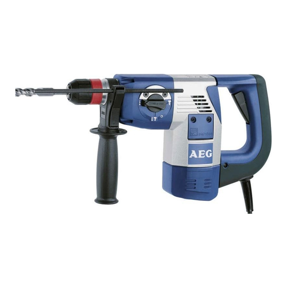
Summary of Contents for Atlas Copco PN 3500 X
- Page 1 Repair Instructions No.187.11/00 Atlas Copco PN 3500 X Electric Power Tools Ltd. 4939 5232 01 (11/00)
- Page 2 Repair Instructions No.187.11/00 PAGE PN 3500 X Special Tools Forcing disks 4931 599 021 Require Special pliers 4931 599 057 (Dis-) Assembly tool 4931 5990 84 Sleeve 4931 599 038 Screw locking agent Omnifit 80 4931 945 651 Mounting stand...
- Page 3 Repair Instructions No.187.11/00 PAGE PN 3500 X Detaching the Remove two screws (5) from the holding- gear housing down device (6) and lever off the switch le- ver (4) with aid of a screwdriver. Remove the four housing screws (1).
- Page 4 Repair Instructions No.187.11/00 PAGE PN 3500 X Disassembling Remove the locking washer (A). the spindle Reduce the rear thrust bearing (9) to its (removing the component parts: outer parts) - washer, - O-ring, - 2 compensating discs (thin) - thrust bearing disc with washer (thick).
- Page 5 Repair Instructions No.187.11/00 PAGE PN 3500 X Disassembling In the middle area of the spindle (1) the spindle there are four deairing holes and four (removing the in- service borings (3). ner locking ring) The diameter of the service borings (3) is smaller than that of the deairing holes.
- Page 6 Repair Instructions No.187.11/00 PAGE PN 3500 X Dismantling the Remove the O-ring (7). reduction gear Attention! The O-ring (7) fits tightly and shaft only serves to lock the discs during (dis-) assembly of the reduction gear shaft. Remove the washer (6) and the thrust bearing (discs (3), (4) and (5)).
- Page 7 Repair Instructions No.187.11/00 PAGE PN 3500 X Dismantling Expel the pin (B). the handle Pull the field supply cables (A) from the contacts and remove them from the field housing. Loosen the screw (8) and remove the gear cover (9).
- Page 8 Repair Instructions No.187.11/00 PAGE PN 3500 X Removing Loosen the screws (1) and (4) and pull out the motor the motor (3). If necessary, hit the motor housing (2) lightly with a plastic hammer for sup- port. Removing and Remove the seal ring (A) and the dismantling the O-ring (2).
-
Page 9: Maintenance
Repair Instructions No.187.11/00 PAGE PN 3500 X Maintenance General It is recommended to regularly submit the tool to maintenance, or as soon as the hammer mechanism gets weak, or when the carbon brushes switch off. When carrying out maintenance all parts of the main- tenance set must be exchanged. - Page 10 Repair Instructions No.187.11/00 PAGE PN 3500 X Cleaning Clean all parts – with the exception of the electrical parts – with cold cleaning agent. Caution! No clean- ing agent should penetrate into the bearing. Clean the electrical parts with a dry brush.
- Page 11 Repair Instructions No.187.11/00 PAGE PN 3500 X Assembly Mounting Place the centring ledges (3) on the the field field (4) (mind the right position, see illus- tration). Insert the field (4) into the motor hous- ing (5), or press it in. If support is needed, lightly hit the motor housing with a plastic hammer from behind.
- Page 12 Repair Instructions No.187.11/00 PAGE PN 3500 X Mounting Insert the motor (1) into the motor hous- the motor ing (3) (take care of the right position: the lug (4) must fit into the relief of the motor housing). Fasten the motor with the screws (2) and (5) (2.5 Nm).
- Page 13 Repair Instructions No.187.11/00 PAGE PN 3500 X Mounting Cover the handle bolt (7) with locking the handle agent, insert it into the housing and screw it down (10 Nm). Push the handle (4) over the bolt and fas- ten the damper element (3) with the wash- ers (2) and (1).
- Page 14 Repair Instructions No.187.11/00 PAGE PN 3500 X Mounting the Insert the support ring (4). angle drive Grease the angle drive (3) and insert it into the motor housing by turning it slightly. Put on the disc (2) and mount the locking ring (1).
- Page 15 Repair Instructions No.187.11/00 PAGE PN 3500 X Mounting the Insert the two disks (3) and the bolt (2) into reduction gear the cylinder (1). shaft and the The reduction gear shaft (4) can only be cylinder inserted as follows: Put together the cylinder (1) and the re- duction gear shaft (4) for adjustment be- fore mounting them.
- Page 16 Repair Instructions No.187.11/00 PAGE PN 3500 X Assembling the Mount the cup springs (1) with the bulg- spindle ings head-on (see illustration). (mounting the Mount the clutch disc (2). outer parts) Insert four balls (B) into the spindle and mount the spindle wheel (3) with the cylin- der pulleys (A).
- Page 17 Repair Instructions No.187.11/00 PAGE PN 3500 X Mounting the Push in the locking ring (2) with aid of the FIXTEC receiver sleeve (1) (service tool) and let it engage. Mount the following parts in the below or- der: - disc (8) - pressure spring (7) and - seal ring (6).


Need help?
Do you have a question about the PN 3500 X and is the answer not in the manual?
Questions and answers