
Related Manuals for Curt Manufacturing REFLEX


Summary of Contents for Curt Manufacturing REFLEX
- Page 1 REFLEX REFLEX BRAKE CONTROL INSTALLATION AND USER GUIDE For use with 12 volt negative ground systems only For trailers with two to eight brakes Read, follow and save this guide for future reference 51130-INS-R1 • PAGE 1...
- Page 2 This package includes: (1) Brake control module with quick plug (1) Slide-in mounting bracket (2) Mounting bracket screws (1) Double-sided mounting tape (1) Surface prep wipe (1) Quick reference card One or more of the following may be needed to complete installation: • Brake control connection harness, supplied with the tow vehicle (if equipped) • CURT quick plug - custom connector for specific vehicles.
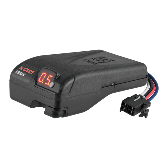
- Page 3 Controls and Components 1. Digital display 2. Load range / calibration button 3. Output adjustment thumb wheel 4. Manual control lever 5. Quick plug connector PAGE 3...
- Page 4 Mounting the Brake Control Module NOTE: Avoid mounting the brake control module near a CB radio or other RF transmitter. 20° 20° 20° 20° Figure 1 Figure 2 Figure 3 1. Determine a suitable mounting location. Mount the unit securely to a solid surface where it is easily accessible to the driver. The area behind the mounting location must be clear to prevent damage while drilling.
- Page 5 2. The mounting bracket can be secured with the screws or foam tape provided. NOTE: The front of the bracket must face the driver. See Figure 4. Figure 4 3. Hold the bracket in place and mark two screw locations. Using a 1/8"...
- Page 6 Wiring NOTE: Removal of factory supplied quick plug may void warranty. Most pick-ups and utility vehicles are equipped with a plug from the factory that allows quick brake control installation. Check the owner's manual for plug availability, location and installation. If the mating plug supplied with the vehicle is no longer available, a CURT quick plug can be used.
- Page 7 connector, attach the white wire from the battery area to the brake control's white wire. Run a 10 gauge blue wire from the tow vehicle's trailer plug 'brake' terminal to the brake control. Using a 10/12 butt connector, connect this wire to the brake control's blue wire. Connect the brake control's red wire to the cold side of the tow vehicle's stoplight switch using a wire tap.
-
Page 8: Wiring Diagram
WIRING DIAGRAM PAGE 8... - Page 9 Once properly connected, the display will show one of the following: Condition Display Meaning Blank screen Sleep mode, touch brake pedal to activate One dot No trailer connected Two dots Trailer connected Manual control activated, no trailer connected 0.5 to 0.9 Trailer is connected, brakes are activated.
-
Page 10: Output Adjustment
Set Load Range Press and release the load range / calibration button until appropriate output range is set. Trailer GVW is less Trailer GVW is up to 50% than tow vehicle GVW more than tow vehicle GVW Trailer GVW is approximately Trailer GVW is more than 100% equal to tow vehicle GVW greater than tow vehicle GVW Set Output With the trailer connected and engine running to ensure proper charge voltage, while parked without the brake pedal applied, slide the manual control lever to the left as far as it... -
Page 11: Troubleshooting Guide
Troubleshooting Guide This brake control is capable of communicating functional errors through the digital display. Condition Display Issue Single dot Brake pedal is pushed, no trailer connection Flashing O.C When manual control is activated indicates no trailer connection. Note: O.C. will flash for a few seconds after a trailer is disconnected from the tow vehicle trailer plug, this is normal Flashing S.C Short circuit condition in the blue brake wire circuit beyond the brake control... - Page 12 Bench Test Wiring Figure 5 PAGE 12...
- Page 13 3. Rotate the output control thumb wheel clockwise as far as it will go. Move the brake control's manual control to the left, the display should show O.C. Connect the brake control's blue wire to the bulb's wire. See Figure 5 on page 12. 4.
Need help?
Do you have a question about the REFLEX and is the answer not in the manual?
Questions and answers