
Related Manuals for FVC TR1101B


Summary of Contents for FVC TR1101B
- Page 1 Installation Guide Transit Side Steps 148 TR1101B FLATLINE VAN CO • SUPPORT@FLATLINEVANCO.COM • 888-667-5576...
- Page 2 All Flatline Van Co products must be properly assembled and secured before attaching to your vehicle. Improper attachment could result in an automobile accident, and could cause serious bodily injury or death to you or to others involved. You are responsible for assembling and securing Flatline Van Co products to your vehicle, checking the mounting points and attachments prior to use, and regularly inspecting the products for wear and or damage.
- Page 3 THANK YOU! ARE YOU EXCITED ABOUT YOUR NEW SIDE STEPS? HERE ARE A FEW THINGS TO DO TOOLS BEFORE BEGINNING THE INSTALLATION PROCESS-- • PLEASE INSPECT THE PRODUCT TO ENSURE THERE WAS NO DAMAGE INCURRED DURING SHIPPING. • IF THERE IS DAMAGE TO REPORT, PLEASE CONTACT OUR CUSTOMER SERVICE DEPARTMENT AS SOON AS POSSIBLE.
-
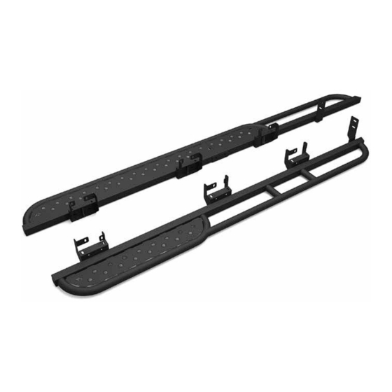
Page 4: Package Contents
PACKAGE CONTENTS DRIVER STEP - FRONT DRIVER STEP - REAR PASSENGER STEP - FRONT PASSENGER STEP - REAR QTY - 1 QTY - 1 QTY - 1 QTY - 1 REAR STEP JOINING BRACKET BRACKET BRACKET BAYONET DRIVER FRONT STEP STEP BRACKET BRACKET SPACER... - Page 5 HARDWARE M8 SCREW FLAT M8-1.25 X 25 1/4 SCREW FLAT M8-1.25 NYLON WASHER FLANGED HEX HEAD WASHER INSERT LOCKNUT SCREW QTY - 12 QTY - 2 QTY - 12 QTY - 46 1/4-20 X 0.75 M8-1.25 X 0.7-3.8 THK FLANGED BUTTON 1/4-20 NYLON INSERT HEAVY DUTY RIVET HEAD HEX DRIVE...
-
Page 6: Driver Side
NOTES ON FACTORY MOUNT POINTS- FVC Side Step Brackets are designed to work with the Ford Factory Side Step mounting locations. Your van may not have come equipped with Side Steps from the factory, so there may be some di erences in mounting hardware required for your installation. -
Page 7: Passenger Side
NOTES ON FACTORY MOUNT POINTS (CONT’D)- 1. Ford factory stud (may need clean up) 2. Ford factory threaded insert (may need clean up) 3. Ford factory unthreaded insert (tapping required) 4. Ford factory pre-existing hole with no insert (requires rivet nut) 5. - Page 8 STEP 1 The first step is to assemble the side steps. Start with one side, grab both ends of the step and slide a Bayonet into the Step-Rear. Apply blue loctite and loosely thread in (2) 1/4-20 x 0.75 Button Head Hex Drive Screws to hold the Bayonet in place, then slide the Step-Front on as shown in the diagram.
- Page 9 FIGURE 1 STEP 2 STUDS- Studs present on the underbody in Location 1 on the diagrams from page 5 & 6 will likely need the undercoating to be cleaned o before a fastener can be threaded onto them. We recommend either using a wire brush with heat gun (Figure 1) or an M8x1.25 Die (Figure 2) to clean the threads and prepare them for hardware.
- Page 10 STEP 3 RIVET NUTS- The next step is to install the rivet nuts in Location 4 on page 5. There should be holes in the underbody of your van sized to accept the provided M8X1.25 Rivet Nuts. We recommend using a pneumatic or electric drill adapter rivet nut tool for this, although a manual rivet nut tool can work if you have enough ground clearance.
- Page 11 STEP 4.1 (DRIVER SIDE) 4.1.1- Install the Step Brackets as shown in the diagram below, noting that the Driver Side has 1 unique bracket that mounts up front. Mount all brackets loosely using the M8-1.25 x 25 Flanged Hex Head Screws on the bottom into the underbody.
- Page 12 STEP 4.2 (PASSENGER SIDE) 4.2.1- Install the (3) Step Brackets using 2 M8-1.25 x 25 Flanged Hex Head Screws (with blue thread lock applied) per bracket, and insert an M8 Screw Flat Washer and M8-1.25 Nylon Insert Locknut onto each stud on the top each bracket as shown below in the diagram.
- Page 13 STEP 5 ATTACH STEPS TO BRACKETS- It’s now time to attach the Side Steps you assembled earlier to the brackets you’ve just mounted to the van. You will FIGURE 4 need 6 M8-1.25 x 25 Flanged Hex Head Screws, and (3) Bracket Spacer-Double per side.
- Page 14 STEP 6 MOUNTING REAR BRACKETS 6.1- On the Driver Side, mount the Rear Step Bracket to the Side Step with a Spacer Plate-Single and M8-1.25 x 25 Flanged Hex Head Screw. Position the bracket to be tight to vertical sheet metal of the van and mark both slots for where to install rivet nuts.
- Page 15 STEP 7 STEP CONNECTING PLATE- Grab the remaining (2) 1/4-20 Fanged Button Head Hex Drive Screws, (2) 1/4 Screw Flat Washers, and 1/4-20 Nylon Insert Locknuts and insert them underneath the Passenger Side Side Step to secure the two halves of the step plate together.
- Page 16 CUSTOMER SUPPORT If you are having any issues with your product, please reach out, and we will make it right. FVC is a company of van and outdoor enthusiasts that design and use our own products, so we want you to be as stoked on your new parts as we are! @flatlinevanco...
Need help?
Do you have a question about the TR1101B and is the answer not in the manual?
Questions and answers