Siebert S302 Series Operating Instructions Manual
Numeric large size displays with analog interface
Hide thumbs
Also See for S302 Series:
- Operating instructions manual (21 pages) ,
- Operating instructions manual (27 pages)

Related Manuals for Siebert S302 Series


Summary of Contents for Siebert S302 Series
- Page 1 Operating instructions Series S302 Numeric large size displays with analog interface...
-
Page 2: Contact
Contact www.siebert-group.com GERMANY Siebert Industrieelektronik GmbH Siebertstrasse, D-66571 Eppelborn P.O. Box 11 30, D-66565 Eppelborn Phone +49 (0)6806 980-0, Fax +49 (0)6806 980-999 email: info.de@siebert-group.com AUSTRIA Siebert Österreich GmbH Mooslackengasse 17, A-1190 Wien Phone +43 (0)1 890 63 86-0, Fax +43 (0)1 890 63 86-99 email: info.at@siebert-group.com... -
Page 3: Legal Note
Siebert , LRD and XC-Board are registered trademarks of Siebert Industrieelektronik GmbH. All other product names mentioned herein may be trademarks or registered trademarks of their respective owners. We reserve the right to make alterations to the technical data and delivery options without notice. - All rights reserved, including the rights of translation. -
Page 4: Table Of Contents
Table of contents 1 Contact 2 Legal note 3 Safety precautions Important information ............................6 Safety ................................. 6 Intended use ............................... 6 Mounting and installation ............................ 6 Grounding ................................6 EMC measures ..............................7 Disposal ................................7 4 Unit description Model designation .............................. - Page 5 Flashing ................................12 Brightness ................................. 12 6 Parametrization Menu ................................. 13 Menu operation..............................13 Menu table ................................ 13 7 Technical data Unit properties ..............................15 Max. power consumption ..........................16 Analog signal input ............................16 Current measurement ............................16 Voltage metering .............................. 17 Switching output ...............................
-
Page 6: Safety Precautions
Safety precautions Important information Read these operating instructions before starting the unit. They provide you with important information on the use, safety and maintenance of the units. This helps you to protect yourself and prevent damage to the unit. Information intended to help you to avoid death, bodily harm or considerable damage to property is highlighted by the warning triangle shown here;... -
Page 7: Emc Measures
EMC measures The devices comply with the EU Directive 2004/108/EC (EMC Directive) and provide the required interference immunity. Observe the following when connecting the operating voltage and data cables: Use shielded data cables. The data and operating voltage cables must be laid separately. They may not be laid together with heavy-current cables or other interference-producing cables. -
Page 8: Unit Description
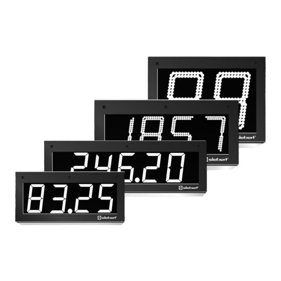
Unit description Model designation This manual applies to units with the following model designation (x = the 'x's in the model designation indicate the size and design of the units): S302-xx/xx/xx-xxx/xx-A0 Unit construction The following figure shows model type S302-05/10/xx-xxx/xx-xx as example for the other model types. The front frame of the housing is locked with quick-action releases. -
Page 9: Principle Circuit Diagram
Principle circuit diagram 8 . 8 . 8 . 8 . 8 . Central Processing Unit Power A/D-Convert. supply unit Tx- COM CO2 NO2 CO1 NO1 Output 2 Output 1 Serial Auxiliary Signal input Function inputs interface Switching outputs voltage Power supply Central Processing Unit The following figure shows the Central Processing Unit, located in the lower part of the housing. -
Page 10: Serial Interface
Serial interface The devices have a serial interface RS422. It is located on the screw-type terminal strip of the control computer and serves for reading out the display values. Menu display The parameterization of the units is carried out in a menu of the menu display. In normal mode, the menu display corresponds to the main display. -
Page 11: Control
Control Input signal The units can be activated by means of the analog signals 0...20 mA, 4...20 mA, 0... 10 V and 2...10 V. The input signal that activates the unit can be set under menu item 1. Display area Start and end value of the display area can be set in the menu items 2 and 3 as follows: The initial value of the display area is set in menu item 2 and the final value is set in menu item 3. -
Page 12: Serial Interface
Serial interface The devices have a serial interface RS422. It transmits the current display value as ASCII data telegram containing 6 characters and the final CR/LF (xxxxxx<CR><LF>) in intervals of approx. 0.25 The characters contain the current display value (right-aligned) including the algebraic sign (left- aligned) or a possible overflow/underflow or wire breakage error. -
Page 13: Parametrization
Parametrization Menu The parameterization of the devices is carried out in a menu in the menu display. Menu operation To start the menu, press both menu buttons simultaneously (approx. 1 sec.) until the first menu item appears in the menu display. It is now possible to navigate in the menu as follows: Next menu item Shortly press key [] Page menu items forward... - Page 14 Menu item Settings Display 0…20 mA* Input signal 4…20 mA 0…10 V 2…10 V Start value -9999…00000*…99999 End value -9999…00000…99999 1* (digit C1 = 0…9) Increment ...
-
Page 15: Technical Data
Technical data Unit properties The model designation is structured as follows: – – – S302 No dimension symbol Dimension symbol 1 Digit 2 Digits 8 Digits Character height 25 mm Character height 57 mm Character height 100 mm Character height 160 mm Character height 250 mm LED Standard... -
Page 16: Max. Power Consumption
Max. power consumption Units with one-sided display [VA] Units with double-sided display [VA] 1 digit 1 digit S302-x1/10/xx-1xx/xx-xx 12 (50) S302-x1/10/xx-2xx/xx-xx 16 (91) S302-x1/16/xx-1xx/xx-xx 22 (50) S302-x1/16/xx-2xx/xx-xx 35 (91) S302-x1/25/xx-1xx/xx-xx S302-x1/25/xx-2xx/xx-xx 2 digits 2 digits S302-x2/06/xx-1xx/xx-xx S302-x2/06/xx-2xx/xx-xx S302-x2/10/xx-1xx/xx-xx 15 (50) S302-x2/10/xx-2xx/xx-xx 21 (91) S302-x2/16/xx-1xx/xx-xx... -
Page 17: Voltage Metering
Voltage metering Input resistance approx. 100 kΩ Input signal 0...±10 V, max. ±40 V Switching output Maximum switching voltage 30 V AC/DC Maximum switching current 500 mA (ohmic load) Screw-type terminals Capacity of terminals 0,14…1,5 mm² Control computer Capacity of terminals 0,2…4 mm² Power supply Housing colors Case front... -
Page 18: Dimensions And Weights
Dimensions and weights Units with one-sided display The following figure shows unit versions S302-04/10/4x-1xx/xx-xx and S302-F3/10/4x-1xx/xx-, representing the other unit versions listed in the following table. 1 digit a [mm] b [mm] c [mm] d [mm] Ø [mm] Weight [kg] S302-01/10/xx-1xx/xx-xx 110 (145) 16 6 (7) - Page 19 Units with double-sided display The following figure shows unit versions S302-04/10/4x-2xx/xx-xx and S302-F3/10/4x-2xx/xx-, representing the other unit versions listed in the following table. Units with character height of 25 mm (S302-xx/03/xx-2xx/xx-xx) and 57 mm (S302-xx/06/xx-2xx/xx-xx) are provided with 2 eyes instead of 4. 1 digit a [mm] b [mm]...
Need help?
Do you have a question about the S302 Series and is the answer not in the manual?
Questions and answers