
Related Manuals for Siebert SX502 Series


Summary of Contents for Siebert SX502 Series
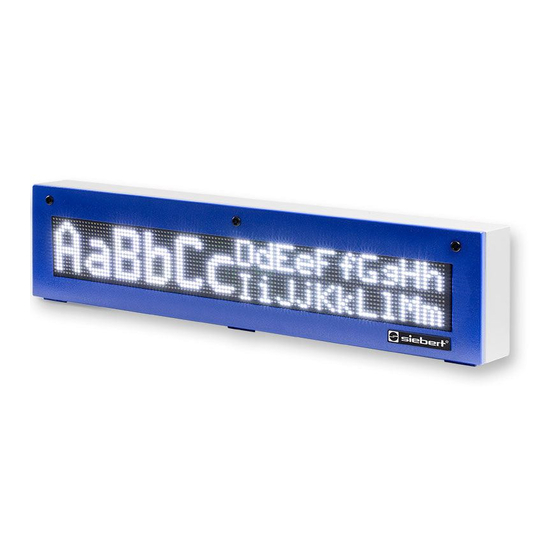
- Page 1 Series SX502 Alphanumeric large size displays with serial interface Operating instructions...
-
Page 2: Contact
Contact www.siebert-group.com GERMANY Siebert Industrieelektronik GmbH Siebertstrasse, D-66571 Eppelborn P.O. Box 11 30, D-66565 Eppelborn Phone +49 (0)6806 980-0, Fax +49 (0)6806 980-999 email: info.de@siebert-group.com AUSTRIA Siebert Österreich GmbH Mooslackengasse 17, A-1190 Wien Phone +43 (0)1 890 63 86-0, Fax +43 (0)1 890 63 86-99 email: info.at@siebert-group.com... -
Page 3: Legal Note
Siebert , LRD and XC-Board are registered trademarks of Siebert Industrieelektronik GmbH. All other product names mentioned herein may be trademarks or registered trademarks of their respective owners. We reserve the right to make alterations to the technical data and delivery options without notice. - All rights reserved, including the rights of translation. -
Page 4: Table Of Contents
Table of contents 1 Contact 2 Legal note 3 Safety precautions Important information ............................7 Safety ................................. 7 Intended use ............................... 7 Mounting and installation ............................ 7 Grounding ................................7 EMC measures ..............................8 Disposal ................................8 4 Unit description Model designation .............................. - Page 5 Application example D ............................18 Data lines RS485 ............................. 18 7 Control Text types ................................. 20 Commands ............................... 20 Display dynamic text ............................21 Static texts ................................ 21 Deleting text ..............................22 Inserting variables ............................22 Deleting text ..............................22 Forced line break ..............................
- Page 6 Handshake ............................... 31 Addressing ................................ 31 Time-out ................................31 Initial text ................................31 Paging ................................31 Character set ..............................32 Language ................................32 Display test ............................... 32 Set time/date ..............................32 10 Status messages Fault messages ..............................33 11 Technical data Unit properties ..............................
-
Page 7: Safety Precautions
Safety precautions Important information Read these operating instructions before starting the unit. They provide you with important information on the use, safety and maintenance of the units. This helps you to protect yourself and prevent damage to the unit. Information intended to help you to avoid death, bodily harm or considerable damage to property is highlighted by the warning triangle shown here;... -
Page 8: Emc Measures
EMC measures The devices comply with the current EU Directive (EMC Directive) and provide the required interference immunity. Observe the following when connecting the operating voltage and data cables: Use shielded data cables. The data and operating voltage cables must be laid separately. They may not be laid together with heavy-current cables or other interference-producing cables. -
Page 9: Unit Description
Unit description Model designation This manual applies to units with the following model designation (x = the 'x's in the model designation indicate the size and design of the units: SX502-xxx/xx/xx-xxx/xx-S0 Unit construction The following figure shows model type SX502-220/05/xx-xxx/xx-xx as example for the other model types. -
Page 10: Principle Circuit Diagram
Principle circuit diagram ① Central Processing Unit ② Power supply unit ③ Power supply ④ Display Ⓑ Battery Ⓓ Sub D connector – serial interface Ⓕ Function input BAL SX502 SER 5.01 10/43... -
Page 11: Central Processing Unit
Central Processing Unit The following figure shows the Central Processing Unit, located in the lower part of the housing. Ⓑ Battery Ⓓ Sub D connector - serial interface Ⓛ Status indicator Ⓜ Menu display Ⓢ Switchable bus termination Ⓣ Menu buttons Ⓥ... -
Page 12: Function Inputs
Function inputs The function inputs are located on the screw-type terminal strip of the control computer. They allow reduction in brightness and flashing of the display, independently of commands via the serial interface (see Chapter xxx). The function inputs are designed for the following signal voltages: Signal voltage: L = -3.5...+5 V (open input = L) H = +18...30 V (active H), M = reference potential... -
Page 13: Character Display
Character display LED matrix The characters are displayed on an LED matrix. A matrix module is 16 LED dots (pixels) high and, depending on the unit version, the following number of pixels wide: Unit versions SX502-x20/xx/xx-xxx/xx-xx: 120 pixels Unit versions SX502-x40/xx/xx-xxx/xx-xx: 240 pixels Character display The units feature several different character sets, which will be elaborated on later. -
Page 14: Multi-Line Units
The SX502 series also includes units with three or four vertically arranged matrix modules. They can display six or eight lines with the Acala 7 character set and three or four lines with the Acala 14 condensed character set. -
Page 15: Character Height
Character height The actual character height depends on the height of a character in pixels and the size of the pixel diameter and spacing. The SX502-xxx/03/xx-xxx/xx-xx unit versions have a pixel diameter of approx. 3 mm and a pixel spacing of approx. 4.7 mm. The SX502-xxx/05/xx-xxx/xx-xx unit versions have a pixel diameter of approx. -
Page 16: Character Table
Character table ... -
Page 17: Interface
Interface Control The units are controlled via the serial interface. It has the formats RS485 and RS232. The interface format is set in menu item 01. Preferably, the interface RS485 is to be used for activation. It is galvanically isolated from all other electric circuits and provides the best preconditions for a reliable and safe operation of the devices due to its physical characteristics. -
Page 18: Application Example B
Application example B Setting in menu item 01: RS485 Setting in menu item 06: ACK/NAK (recommended) Application example C Setting in menu item 01: RS485.4 Setting in menu item 06: ACK/NAK (recommended) Application example D Setting in menu item 01: RS485.2 Setting in menu item 06: ACK/NAK (recommended) Data lines RS485 To achieve the highest possible interference immunity, the data lines of the RS485 have to be... - Page 19 The shielding is connected on both line ends For the signal ground (GND) use a wire pair short-circuited on both ends in the data cable. The shielding may not be used as the signal ground. A twisted pair of conductors is used each for Tx+ and Tx- and for Rx+ and Rx-. Non-observance of this instruction causes the protective function of the twisted-pair cable to be lost.
-
Page 20: Control
Control Text types The devices can display dynamic and static texts. Dynamic texts can be changed while the unit is running. They are generated from within the process and sent to the display as data telegram. Static texts cannot be changed while the unit is running. They are compiled using the PC tool 'Text Manager' included on data carrier and loaded in the text memory via the serial interface. -
Page 21: Display Dynamic Text
Orange [18] Place holders for variables Inserting place holders for variables [19] Inserting time Current time (HH:MM:SS) [20] Hour of current time (HH) [21] Minute of current time (MM) [22] Second of current time (SS) [23] Inserting current date Current date, four-digit year (TT.MM.JJJJ) [24] Current date, two-digit year (TT.MM.JJ) [25]... -
Page 22: Deleting Text
In principle, updating could occur with dynamic texts containing both the fixed and the variable text components. However, the data transfer required here is considerable. The SX502 series offers the advantageous alternative of a one-time transmission of the fixed text components to the display and subsequent insertion of just the appropriate characters (variables) to update the variable text components. -
Page 23: Marquee Text
Flashing of the entire display can also be activated with an H-signal at function input F2 (priority over commands). Marquee text Marquee text display is activated from the current position in the text with the $Y command [9]. It remains active up to the end of the text or a forced line break ($C). If a seven pixel-high font is currently selected, e.g. -
Page 24: Brightness
Brightness The brightness of the display can be reduced with the $B1 command [36] and reset to normal brightness with the command $B0 [35]. The brightness of the display can also be reduced with an H-signal on function input F1 (priority over commands). -
Page 25: Individual Line Selection
Individual line selection Application The activation of the devices as described in chapter "Control" is optimized for applications in which individual texts are shown in the display. Longer texts are written in several lines of the display due to the automatic line break. When the text contains more characters than can be displayed, it will be automatically displayed in paging mode. -
Page 26: Display Dynamic Text
For the other device functions, the commands described in Chapter 7 shall apply. Display dynamic text To display a dynamic text, its characters (cc…) are transmitted to the selected line as a data telegram [42]. Any text in the display is deleted when a new text is called up. Display static text A static text in the selected line can be loaded using the $Lxx$Tn... - Page 27 Line 01 (Command $M1$L01…) + + + + Character height 50 mm + + + + Line 02 (Command $M1$L02…) + + + + Character height 50 mm + + + + Line 03 (Command $M1$L03…) + + + + Character height 50 mm + + + + Line 04 (Command $M1$L04…) + + + + Character height 50 mm + + + + Character height 100 mm...
-
Page 28: Parameterization
Parameterization Menu The parameterization of the devices is carried out in a menu in the menu display. In normal operation, status messages appear in the menu display. Menu operation To start the menu, press both menu buttons simultaneously (approx. 1 sec.) until the first menu item appears in the menu display. - Page 29 Menu item Settings Menu display Serial interface RS232 RS485 RS485 (4-wire bus) RS485 (2-wire bus) RS232 Programming operation Data format 8 bit* Parity No parity* Odd parity Even parity ...
- Page 30 30 Seconds Character set Acala 7* Acala 7 extended Acala 14 condensed Acala 14 extended Acala 7 P / user-defined character set 7 pixel Acala 14 / user-defined character set 14/16 pixel Acala 16 condensed ...
-
Page 31: Serial Interface
Serial Interface Select in menu item 01 between the interface formats which are available in the unit (RS485 und RS232). Preferably, the interface RS485 is to be used for interfacing. In the interface format RS485, you can select several settings in the menu item 01. Data format, parity, baud rate, protocol and protocol reply are set in menu items 02 to 06. -
Page 32: Character Set
Character set In menu item 22, you can set the default character set used to display the texts. Character sets Acala 7, Acala 7 extended, Acala 14 condensed and Acala 14 extended are permanently installed in the units. Also the character sets Acala 16, Acala 16 condensed und Acala 16 extended. The character set Acala 7 P can be loaded with the setting ... -
Page 33: Status Messages
Status messages Fault messages Serious faults due to improper operation or faulty operating conditions are indicated in the display. The following messages are possible: Fault message Cause Rectification No Text The called up text is not available in the text The text is to be loaded into the text memory memory. -
Page 34: Technical Data
Technical data Unit properties The model designation is structured as follows: – – – SX502 2 lines 4 lines 6 lines 8 lines 20 characters/line* 40 characters/line* Character height 33/66/75 mm Character height 50/100/120 mm LED Standard LED for outdoor use LED color red LED color red/green/orange switchable Display readable on one side... -
Page 35: Housing Colors
Housing colors Case front RAL 5002 ultramarine Case rear part RAL 7035 light grey Front frame SX502-xxx/xx/xR-xxx/xx-xx plastic, tinted red, non-reflective SX502-xxx/xx/xM-xxx/xx-xx plastic, clear, non-reflective Ambient conditions 0…40 °C Operating temperature -30…85 °C Storage temperature Relative humidity max. 95 % (non-condensing) Max. -
Page 36: Screw-Type Terminals
The power consumption for the type SX502-xx/xx/0x-xxx/xx-xx is also valid for the type SX502- xx/xx/2x-xxx/xx-xx (LEDs for external use). For units with built-in heating, the values for power consumption specified in the table increase by approx. 10 – 200 VA (exact values on request), depending on the unit size. Screw-type terminals Control computer Capacity of terminals 0,14…1,5 mm²... -
Page 37: Dimensions And Weights
Dimensions and weights Units with character height of 33/66/75 mm and one-sided display The following figure shows unit version SX502-640/03/0x-1xx/xx-xx, representing the other unit versions listed in the following table. All dimensions are in mm. LG1, LG2 and LG3 are ventilation grates on units ventilated by other means. The ventilation grates and their arrangement are not pictured to scale. - Page 38 Units with character height of 33/66/75 mm and double-sided display The following figure shows unit version SX502-640/03/0x-2xx/xx-xx, representing the other unit versions listed in the following table. All dimensions are in mm. LG1, LG2, LG3 and LG4 are ventilation grates on units ventilated by other means. The ventilation grates and their arrangement are not pictured to scale.
- Page 39 Units with character height of 50/100/120 mm and one-sided display The following figure shows unit version SX502-820/05/0x-1xx/xx-xx, representing the other unit versions listed in the following table. All dimensions are in mm. LG1 and LG2 are ventilation grates on units ventilated by other means. The ventilation grates and their arrangement are not pictured to scale.
- Page 40 The following figure shows unit version SX502-640/05/0x-1xx/xx-xx, representing the other unit versions listed in the following table. All dimensions are in mm. LG1, LG2 and LG3 are ventilation grates on units ventilated by other means. The ventilation grates and their arrangement are not pictured to scale. The following table specifies the ventilation grates of the individual unit versions.
- Page 41 Units with character height of 50/100/120 mm and double-sided display The following figure shows unit version SX502-820/05/0x-2xx/xx-xx, representing the other unit versions listed in the following table. All dimensions are in mm. LG1, LG2, LG3 and LG4 are ventilation grates on units ventilated by other means. The ventilation grates and their arrangement are not pictured to scale.
- Page 42 The following figure shows unit version SX502-440/05/0x-2xx/xx-xx, representing the other unit versions listed in the following table. All dimensions are in mm. LG1, LG2 and LG3 are ventilation grates on units ventilated by other means. The ventilation grates and their arrangement are not pictured to scale. The following table specifies the ventilation grates of the individual unit versions.
- Page 43 The following figure shows unit version SX502-840/05/0x-2xx/xx-xx, representing the other unit versions listed in the following table. All dimensions are in mm. LG1, LG2, LG3 and LG4 are ventilation grates on units ventilated by other means. The ventilation grates and their arrangement are not pictured to scale. The following table specifies the ventilation grates of the individual unit versions.
Need help?
Do you have a question about the SX502 Series and is the answer not in the manual?
Questions and answers