Siebert S102 Series Operating Instructions Manual
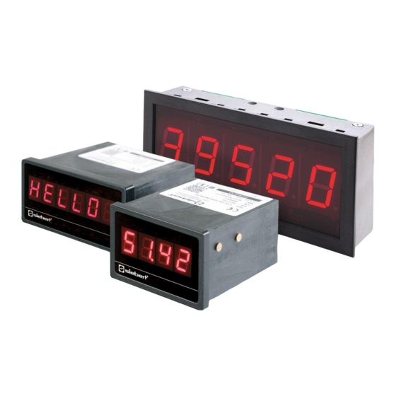
Numeric displays in build-in housings with analog interface
Hide thumbs
Also See for S102 Series:
- Operating instructions manual (44 pages) ,
- Operating instructions manual (22 pages) ,
- Operating instructions manual (32 pages)

Related Manuals for Siebert S102 Series


Summary of Contents for Siebert S102 Series
- Page 1 Series S102 Numeric displays in build-in housings with analog interface Operating instructions...
-
Page 2: Contact
Contact www.siebert-group.com GERMANY Siebert Industrieelektronik GmbH Siebertstrasse, D-66571 Eppelborn P.O. Box 11 30, D-66565 Eppelborn Phone +49 (0)6806 980-0, Fax +49 (0)6806 980-999 email: info.de@siebert-group.com AUSTRIA Siebert Österreich GmbH Mooslackengasse 17, A-1190 Wien Phone +43 (0)1 890 63 86-0, Fax +43 (0)1 890 63 86-99 email: info.at@siebert-group.com... -
Page 3: Legal Note
Siebert , LRD and XC-Board are registered trademarks of Siebert Industrieelektronik GmbH. All other product names mentioned herein may be trademarks or registered trademarks of their respective owners. We reserve the right to make alterations to the technical data and delivery options without notice. - All rights reserved, including the rights of translation. -
Page 4: Table Of Contents
Table of contents 1 Contact 2 Legal note 3 Safety precautions Important information ............................5 Safety ................................. 5 Intended use ............................... 5 Mounting and installation ............................ 5 Grounding ................................5 EMC measures ..............................5 Disposal ................................6 4 Model designation 5 Principle circuit diagram 6 Features 7 Signal input... -
Page 5: Safety Precautions
Safety precautions Important information Read these operating instructions before starting the unit. They provide you with important information on the use, safety and maintenance of the units. This helps you to protect yourself and prevent damage to the unit. Information intended to help you to avoid death, bodily harm or considerable damage to property is highlighted by the warning triangle shown here;... -
Page 6: Disposal
Disposal Units or unit parts which are no longer needed are to be disposed of in accordance with the regulations in effect in your country. BAL S102 ANA 1.10 6/14... -
Page 7: Model Designation
Geltungsbereich Model designation This manual applies to units with the following model designation (x = the 'x's in the model designation indicate the size and design of the units). S102-x6/14/0x-00x/0B-Z0 Character height 14 mm, 6 digits S102-x5/25/0x-00x/0B-Z0 Character height 25 mm, 5 digits Principle circuit diagram Units with 14 mm character height Units with 25 mm character height... -
Page 8: Features
Features Brillant LED display Bipolar signal inputs ±20 mA / ±10 V Completely scalable display range Programmable increments and averaging Two programmable switching outputs with zero-voltage contacts Wire-break detection Serial signal output Hold input Parameterization via menu Plug-in screw terminal strip Signal input The units must be parameterized before they can be controlled. -
Page 9: Switching Outputs
Switching outputs The devices have two switching outputs (relays) with potential-free make contacts (output 1: CO1, NO1; output 2: CO2, NO2). The switching points can be set in menu items 6 and 7. In menu items 6 (output 1) and 7 (output 2), the number of the menu item and the current setting appear alternately in the display. -
Page 10: Stop Display
Stop display With an H signal on input F, the display can be stopped while the analog input signal continues to be evaluated. Input F is PLC compatible and designed for the following signal voltages: L signal = -3.5...+5 V, H signal = +18...30 V (active H). -
Page 11: Parameterization
Parameterization Menu operation To start the menu, press both menu buttons simultaneously (approx. 1 sec.) until the first menu item appears in the menu display. It is now possible to navigate in the menu as follows: Next menu items forward Press key [] long Page menu items forward Shortly press key []... - Page 12 Menu item Settings Display 0…20 mA* Input signal 4…20 mA 0…10 V 2…10 V Start value -99999…000000*…999999 -9999…00000*…99999 -99999…000 00…999999 End value -9999…00000…99999 1* (digit C1 = 0…9) Increment (digit C1 = 0/5) ...
-
Page 13: Technical Data
Technical data Technical data Analog signal input Resolution 16 Bit Measurement rate approx. 4/s Measurement error 0,02% of end value ±1 digit (25 °C) Temperature coefficient <50 ppm/°C Current measurement approx. 22 Ω Input resistance 0…±20 mA, max. ±100 mA Input range Voltage measurement approx. -
Page 14: Dimensions
Dimensions Units with 14 mm character height Units with 25 mm character height (1) Panel outcut (2) Menu buttons (3) Screw terminal strip (4) Rear view BAL S102 ANA 1.10 14/14...
Need help?
Do you have a question about the S102 Series and is the answer not in the manual?
Questions and answers