Table of Contents
Advertisement
Quick Links
Advertisement
Table of Contents

Related Manuals for Avid Technology ISIS 7000


Summary of Contents for Avid Technology ISIS 7000
- Page 1 ® ® Avid ISIS 7000 Setup Guide...
- Page 2 This document is supplied as a guide for Avid ISIS 7000. Reasonable care has been taken in preparing the information it contains.
- Page 3 Copyright (C) 1989, 1991 by Jef Poskanzer. Permission to use, copy, modify, and distribute this software and its documentation for any purpose and without fee is hereby granted, provided that the above copyright notice appear in all copies and that both that copyright notice and this permission notice appear in supporting documentation.
- Page 4 Torq Xponent, Transfuser, Transit, TransJammer, Trigger Finger, Trillium Lane Labs, TruTouch, UnityRAID, Vari-Fi, Velvet, Video the Web Way, VideoRAID, VideoSPACE, VideoSpin, VTEM, Work-N-Play, Xdeck, X-Form, Xmon, XPAND!, Xponent, X-Session, and X-Session Pro are either registered trademarks or trademarks of Avid Technology, Inc. in the United States and/or other countries.
-
Page 5: Table Of Contents
Chapter 1 Avid ISIS 7000 System Overview ....... 21 Hardware Overview and Naming Convention ......21 System Director. - Page 6 Supported Cabling ..........39 Connecting the Engine CX-4 Cable .
- Page 7 Chapter 3 Installing Software and Configuring 10-Gb Link Aggregation ..73 IP Addressing Overview ..........73 Configuration Overview.
- Page 8 Appendix A Avid ISIS 7000 Upgrade Guidelines ......117 Health Check ........... . . 117 Software Upgrade .
- Page 9 Appendix D Avid ISIS Recommended Maintenance ......157 Minimum Storage Space Requirement ........157 Daily Maintenance .
- Page 10 Class A Equipment ..........183 Korean EMC Regulations.
-
Page 11: Symbols And Conventions
Avid editing workstations. This document describes the features for all Avid ISIS 7000 shared storage networks. Therefore, your system might not contain certain features that are covered in the documentation. Symbols and Conventions... -
Page 12: If You Need Help
Symbol or Convention Meaning or Action Courier Bold font identifies text that you type. Courier Bold font Ctrl+key or mouse action Press and hold the first key while you press the last key or perform the mouse action. For example, Command+Option+C or Ctrl+drag. If You Need Help If you are having trouble using your Avid product: 1. -
Page 13: Accessing The Online Documentation
Accessing the Online Documentation Accessing the Online Documentation The Avid ISIS online documentation contains all the product documentation in PDF format. You can access the documentation in the top-level AvidUnityISISDocumentation folder on the Avid ISIS installer DVD or USB. The documentation describes the features and hardware of all models. Therefore, your system might not contain certain features and hardware that are covered in the documentation. -
Page 15: Software Upgrade
Avid ISIS. Each Avid ISIS release could have different upgrade requirements, you must read the upgrade details in the ReadMe for each software release. For detailed instructions on performing upgrades, see “Avid ISIS 7000 Upgrade Guidelines” on page 117. Software Upgrade This section list the components and procedures to follow when performing a software upgrade from Avid ISIS v1.4 and later to the current release. - Page 16 Before installing the new client software, save the client settings and preferences. Depending on your Avid ISIS version, different Preferences settings are saved when upgrading. For more information on what is saved per version, see the Avid ISIS 7000 ReadMe.
-
Page 17: Hardware Upgrade
After the Avid ISIS engines restart, the ISSs continue with the install (no additional user intervention is necessary). For information on the Monitoring tool, see the Avid ISIS 7000 Administration Guide. Make the newly upgraded System Director your Active System Director. -
Page 18: New System Director And Engine Installation
Click “Stop System Director” • Go to “Configuration” tab • Click “Create New Active” Configure the first Engine (IP Addresses), see the Avid ISIS 7000 Administration Guide. • Start ISS Agent via Management port • Under System > Basic set IP Address ... -
Page 19: Switch And Isb Upgrade Utility
Upgrade ISB and ISS, see “Installing Software on the Engines” on page Add Storage Elements, see the Avid ISIS 7000 Administration Guide. Create Storage Groups, see the Avid ISIS 7000 Administration Guide. Create Workspaces, see the Avid ISIS 7000 Administration Guide. -
Page 20: Recreating A File Systems
Deleting and creating a new file system is not common but if it is needed, this checklist provides the order and tasks to be completed. All of the tasks listed in this checklist are described in the Avid ISIS 7000 Administration Guide. Use the following checklist when deleting and recreating a new file system:... -
Page 21: Avid Isis 7000 System Overview
The Avid ISIS system enables multiple clients to capture, play, and edit video and audio media. This chapter provides an overview of the Avid ISIS 7000 system and the basic function of each Avid hardware component within the system. This guide describes how to connect cables between components that create a basic system and then how to connect more than one basic system together to create a larger, redundant system. - Page 22 1 Avid ISIS 7000 System Overview Product Nomenclature (Continued) Product name Term used and description Avid ISIS client Client, defined as a user’s workstation or server with Avid ISIS client software that allows that system to mount workspaces Avid ISIS storage blade...
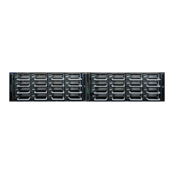
- Page 23 The Avid ISIS documentation refers to ISX2000 and ISS2000 switches as v2.x hardware and ISX1000 and ISS1000 switches as v1.x hardware. Basic Avid ISIS 7000 Shared Storage Network Hardware Rear view Front view...
-
Page 24: System Director
1 Avid ISIS 7000 System Overview System Director The System Director is 2U in size (see “System Director Front Panel” on page 25) and manages the metadata by storing directory information and file attributes. The System Director does not store the data used by share clients (for example media files), these data files are stored on the ISBs within the engine. -
Page 25: System Director Front Panel
System Director System Director Front Panel The following figure shows the front view and control panel of the System Director. System Director Front View DVD/CD-ROM RAID disk (ID 1) Control panel System disk (ID 0) The following table describes the control panel shown in the previous figure. System Director Control Panel Letter Description... -
Page 26: System Director Rear Connections
1 Avid ISIS 7000 System Overview System Director Rear Connections The following figure shows the rear panel of the System Director and the function of each connection. System Director Rear View Dual NIC Ethernet adapter board Slots not used Power supplies... -
Page 27: Engine
Engine Engine The engine contains the ISBs, ISSs, IXSs, power supplies, and an internal midplane. The engine stores the data created and shared by the clients. The data is passed in and out of the engine through the switches. The engine contains: •... -
Page 28: Engine Rear View
1 Avid ISIS 7000 System Overview Engine Rear View The following figure shows the rear of the engine in a configuration that contains the following: • Three power supplies (with fans) • Integrated Switch blade (ISS) • Integrated Expansion Switch blade (IXS) In a basic configuration containing two engines, each of the engines contains two ISS modules. -
Page 29: Integrated Ethernet Switches
The connections on the ISS module are used for the following: • Management connection — used to configure the Avid ISIS 7000 engine hardware during installation. This information is used by Avid representatives to originally configure your system before turning it over to you. -
Page 30: Storage Configurations
Avid ISIS 7000 switch hardware shipped with v1.x (ISS1000 and IXS1000) does not support 512 KB chunk sizes. If you have Avid ISIS 7000 v2.x software running on v1.x switches, you must select the 256KB chunk size when adding storage elements to the file system to create Storage Groups. -
Page 31: Client
1 Gb or 10 Gb Ethernet connection, communicates with the ISBs through the ISS to create, modify, and read files stored in the actual ISB. Avid ISIS 7000 supports up to 330 clients (150 active clients), each using dual-stream video and up to 8 tracks of audio. -
Page 32: Network Zone Configurations
Zone 3 — MediaManager Select, Instinct, Assist, certain editors (for example, Avid NewsCutter); typical formats include DV25, DV50/IMX-50, MPEG-2 proxy (2 Mb/s) • Zone 4 — MediaManager Select, Instinct, Assist; typical formats include DV25, MPEG-2 proxy (2 Mb/s) The following four examples show different types of Avid ISIS 7000 configurations. -
Page 33: Zone 1 Clients (Direct Connected)
A Zone 1 (direct connect) configuration consists of a group of clients connected directly to the 1-Gb and 10-Gb connections of the ISS in the engine. The System Director also connects to both subnets via both ISS modules using a 1-Gb port. Avid ISIS 7000 Zone 1 Network Configuration Intel Pro 1000 Client systems... - Page 34 1 Avid ISIS 7000 System Overview 1 Gb Ports in Zone 1 ISS1000 and IXS1000 Switches ISS2000 and IXS2000 Switches Number Two System Two System of ISIS One System Directors One System Directors Engines Director (failover) Director (failover) 108b a. This is due to the use of IXS switches instead of an ISSs.
-
Page 35: Zone 2 Clients (Indirect Connect) Configuration
Director also connects to both subnets via both ISS modules using a 1-Gb port. Depending upon the switch configuration, each client shown connected to the external switch is connected to one of the two subnets through one of the two 10-Gb connections. Avid ISIS 7000 Zone 2 Network Configuration Intel Pro 1000 Client systems... - Page 36 1 Avid ISIS 7000 System Overview Foundry FES-X424 Switch 10-Gb ports 1-Gb ports Ports 1 - 12 Ports 13 - 24 Port 25 Port 26 Port 24 Each VLAN on the switch is allowed to support up to 12 connections but the size of the Storage Groups and engine determine the overall client count.
-
Page 37: Zone 1 And Zone 2 Clients Mixed Configuration
Director in case of a failure. Both System Directors also connect to each other through the onboard Ethernet connections to monitor if one of the System Director fails. Avid ISIS 7000 Zone 1 and Zone 2 Mixed Network Configuration Intel Pro 1000... - Page 38 Network through an Ethernet switch that contains a 10-Gb port connected to an ISS located in the engine. The System Director connects to the both subnets via both ISS modules using a 1-Gb port. Avid ISIS 7000 Zone 3 and Zone 4 Network Configuration Zone 4 Zone 4 clients...
-
Page 39: Link Aggregation Support
1 Gb ports on an ISS The minimum GigE cable length for Avid network products is 6 feet or 2 meter. Avid Interplay servers to shared storage networks Avid AirSpeed capture and playback servers to shared storage networks Avid ISIS 7000 management port to laptop... - Page 40 1 Avid ISIS 7000 System Overview Supported Cables (Continued) Cable Connection Connector Style and Maximum Cable Type Function Length Optical cables Connects: The maximum length for 10 Gb Ethernet cable is defined by the core diameter (measured in 10-Gb port of switch to optical...
-
Page 41: Connecting The Engine Cx-4 Cable
Supported Cabling Supported Cables (Continued) Cable Connection Connector Style and Maximum Cable Type Function Length Avid ISIS Transceiver used in: SC connector X2 optical transceivers ® Cisco 4948 and 4900M X2 = Cisco X2-10GB-SR for MMF X2 = Cisco X2-10GB-LR for SMF Avid ISIS Transceiver used in: LC connector... -
Page 42: Removing The Avid Engine Interconnect Cable
1 Avid ISIS 7000 System Overview Damage can occur when disconnecting the Avid engine Interconnect cable from the switch board if not done properly. Care should be taken to reduce strain on the ISS switch blades by organizing and dressing the ethernet cables and CX-4 cables. -
Page 43: 10-Gb Link Aggregation Overview
Link Aggregation Groups. Supported in Link Aggregation Avid ISIS 7000 supports 10-Gb link aggregation (between the ISS and the Avid Production Network switch) and Hi-Gig link aggregation (between two IXS). Avid ISIS software supports the link aggregation standard clause 43 of 802.3-2005 (also known as 802.3ad). -
Page 44: Load Balancing
1 Avid ISIS 7000 System Overview Load Balancing The software balances the load across multiple 10-Gb aggregated links based on source and destination IP addresses. Failover If a 10-Gb trunk link fails, the software load balances the traffic among the remaining trunk links. -
Page 45: Supported Functionality
Supported Cabling Supported Functionality From the Link Aggregation menu in the switch agent, you can: • View current settings — This displays the current link aggregation configurations, showing all currently configured groups. The user may also modify a group or delete a group from this page. - Page 46 1 Avid ISIS 7000 System Overview...
-
Page 47: Connecting The Isis Equipment
Connecting the ISIS Equipment This chapter explains how to rackmount and connect the system hardware. To do this, a system installation check list is provided to help you perform the installation in the correct order. The installation check list continues past the information in this chapter and points you to the correct area in this document or the ReadMe file to continue the installation. -
Page 48: Rack-Mounting Examples
2 Connecting the ISIS Equipment Rack-Mounting Examples Avid supports more than one Avid ISIS rack configuration. You should have discussed the layout for your system with an Avid representative prior to purchase. The following examples show a few of the supported rack configurations. Single Rack - Two Engines - One System Director System Director... - Page 49 Rack-Mounting the Equipment Single Rack - Four Engines - One System Director Switch System Director MGMT MGMT Engines MGMT MGMT MGMT MGMT...
-
Page 50: Installing Rack-Mount Rails And Brackets
2 Connecting the ISIS Equipment Dual Rack - Four Engines - Failover System Rack 1 Switch Rack 2 System Directors Engines MGMT MGMT MGMT MGMT MGMT MGMT Installing Rack-Mount Rails and Brackets All Avid ISIS rack-mount components are supplied with either mounting rails or brackets. You should follow the manufacturer’s installation instructions supplied with each component to correctly attach the rails or brackets to the rack rails. -
Page 51: Installing System Director And An Avid Isis Engine
Rack-Mounting the Equipment Installing System Director and an Avid ISIS Engine The System Director and storage elements are placed into a rack for easy access to the cables, connectors, and drives. The following list provides recommendations you should take into account prior to rack-mounting Avid ISIS equipment: •... - Page 52 2 Connecting the ISIS Equipment To mount the engine into the rack: 1. Screw the brackets to the rear of the rack as shown in the following figure. Rear 2. Make sure that the blades and power supplies are not in the engine. 3.
-
Page 53: Installing Blades And Power Supplies
Installing Blades and Power Supplies Installing Blades and Power Supplies Once the engine has been mounted you can install the power supplies and blades. Only trained Avid technicians should remove and replace the power supply when power is applied to the system. Since power to the system is still on, you must always keep your hands external to the engine when a power supply is missing from the engine. -
Page 54: Installing Ixs And Iss Switches
2 Connecting the ISIS Equipment 7. Place the power supply into the engine as shown in the following figure and slowly push the power supply into the slot. Screws 8. Turn the screws until tight. 9. Repeat step 6 through step 8 until all power supplies are installed. Installing IXS and ISS Switches The location of the ISS and IXS switches in the stack are very important. -
Page 55: Connecting The Application Key
Before you start the System Director, you need to connect the Avid ISIS system USB application key (also called a dongle). The USB application key determines how many Avid ISIS 7000 clients can simultaneously use your system. Do not lose the USB application key. Your Avid ISIS system does not function without it. -
Page 56: Connecting Power To Equipment
The three power supplies “load share” to allow the balanced distribution of V ac power into each Avid ISIS 7000 engine. Usually, a minimum of two of the three power supplies must be operational at one time for the engine to function properly. The fans in each power supply cool the supply and provides airflow for the engine. -
Page 57: Three 20-Amp V Ac Circuits For Three Engines
Connecting Power to Equipment Three 20-Amp V AC Circuits for Three Engines When you are using three 20-amp circuits for three engines, they are configured as follows: Basic Power Connection for Three ISIS Engines 20 Amp System Director 20 Amp System Director Engine Engine... -
Page 58: Three 20-Amp V Ac Circuits For Two Engines
2 Connecting the ISIS Equipment Three 20-Amp V AC Circuits for Two Engines When using three 20-amp circuits for the engine, they are configured as follows: First Example of Power Connection for Two ISIS Engines 20 Amp System Director 20 Amp System Director Engine Engine... -
Page 59: Two 20-Amp V Ac Circuits For Two Engines
Connecting Power to Equipment Two 20-Amp V AC Circuits for Two Engines The following configuration is not recommended by Avid, but some locations might need to connect in this manner. When using two 20-amp circuits for the engine, they are configured as follows: Second Example of Power Connection for Two ISIS Engines 20 Amp System Director... -
Page 60: Connecting An Engine With V2.X Hardware
The 64-bit System Directors introduce in Avid ISIS 7000 v2.0 can be used with v2.x and v1.x generation switches in the engines. The two v2.x switches are branded with an IXS2000 and ISS2000 silk-screen. -
Page 61: Engine Configuration V2.X Hardware Guidelines
Use the following list to help you when you connect the System Director, laptop for configuration, and clients to the Avid ISIS 7000 system. • A laptop (or any computer running a Windows operating system) is used in the following examples for configuring the engine at the beginning of the installation or for maintenance by an Avid representative. - Page 62 6. You are asked for the default password. Type se-admin The Avid ISIS 7000 Integrated Switch Blade Window appears. 7. Type the following into the Chassis Configuration window: Starting IP addresses. Enter the IP addresses for both subnets, see “IP Addressing...
- Page 63 Connecting an Engine with v2.x Hardware Date, Time, and Time Zone or Enable network time protocol If your network has a network time protocol (NTP) server, you can enter the IP address of that server in the Chassis Configuration window. NTP Server 1 is for the primary NTP server and if you have a secondary NTP server, enter the secondary IP address in NTP Server 2.
-
Page 64: Two-Engine Stacking
2 Connecting the ISIS Equipment Two-Engine Stacking To stack two engines: 1. Complete the procedure “Setting-Up Network Addresses In the Stack” on page 2. Open a left-side Switch Web page. 3. Go to System > Configuration > Add/Remove chassis. 4. Click Add and wait for the progress bar to complete. 5. -
Page 65: Three- To Twelve-Engine Stacking Summary With V2.X Switches
When accessing the Agent Web pages for the engines, use your laptop through the Management port or the Switch Agent Web through the Avid ISIS 7000 software on your System Director. Information on installing the software on the system Director is described... -
Page 66: Three- To Twelve-Engine Connections With V2.X Switches
2 Connecting the ISIS Equipment In three- to twelve-engine configurations with ISX2000 switches, two IXSs are installed in the first engine, see “Three- to Twelve-Engine Connections With v2.x Switches” on page The IXS2000 ports 1 through 11 are referred to from left to right as shown in the following figure. - Page 67 6. You are asked for the default password. Type se-admin The Avid ISIS 7000 Integrated Switch Blade Window appears. 7. Type the following into the Chassis Configuration window: Starting IP addresses. Enter the IP addresses for both subnets, see “IP Addressing...
- Page 68 2 Connecting the ISIS Equipment 8. Click Submit. A Dialog box might appear with an informational warning and can be disregarded. The first engine is now properly addressed. 9. Click Add/Remove Chassis to go to the Add a Chassis page.
- Page 69 Connecting an Engine with v2.x Hardware 10. Click Add and wait for the progress bar to complete.
- Page 70 2 Connecting the ISIS Equipment 11. Immediately attach an interconnect cable from port 1 of the left IXS to the left ISS interconnect port of the second engine. Left Subnet Twelve-Engine Connections Third engine Fifth engine Seventh engine Second engine Fourth engine Sixth engine 11 11...
- Page 71 Connecting an Engine with v2.x Hardware 14. Attach the System Director to client port and assign an appropriate IP address for the left subnet. Verify that you can ping all the switches in the left stack at the expected IP addresses. 15.
-
Page 72: Hi-Gig Link Aggregation Group
2 Connecting the ISIS Equipment 4. Attach the System Director to client port and assign an appropriate IP address for the right subnet. Verify that you can ping all the switches in the right stack at the expected IP addresses. All switches in the stack (left and right sides) should now be pingable from the System Director. -
Page 73: Installing Software And Configuring 10-Gb Link Aggregation
Installing Software and Configuring 10-Gb Link Aggregation This chapter describes how to connect and configure the System Director and other Avid ISIS hardware. Since the number of different configurations are endless, it uses a configuration with four engines and one System Director as an example. If you have questions, please call your Avid representative or your local ACSR. - Page 74 3 Installing Software and Configuring 10-Gb Link Aggregation The following figure shows the front and rear view of a engine. Use the following two figures and bulleted list to understand how static IP addresses are assigned to each engine. Front and Rear of a Engine Upper left Lower right Left side...
- Page 75 IP Addressing Overview When you assign subnet addresses internally and have more than one engine, all ISSs and IXSs on the left side of the rear of the engine are on one subnet, while all ISSs and IXSs on the right side of the rear of the engine are on the other subnet. See the following illustration for a pictorial view of address assignments described in the following bullet.
- Page 76 3 Installing Software and Configuring 10-Gb Link Aggregation Static Engine Internal IP Address Assignments First engine Subnet 10 Subnet 20 c t i c t i Second engine Expansion/switch blade Expansion/switch blade...
-
Page 77: Configuration Overview
The Avid ISIS 7000 product documentation is in PDF format. You can access the documentation in the AvidISISDocumentation folder on the Avid ISIS installer kit. You need to download and install Acrobat Reader on your Avid ISIS 7000 before you can access the PDF documentation. - Page 78 3 Installing Software and Configuring 10-Gb Link Aggregation 3. (Option) The Avid ISIS 7000 software kit is also available on the Avid Download Center (www.avid.com/support/downloadcenter). Uncompress (unzip) the downloaded software kit in the new folder on the Avid ISIS 7000 system.
- Page 79 Select the ISIS 7000 software kit from the “Select Software Package” menu. • ISIS 7000 — Selects the ISIS 7000 software kit. Select this menu item to install the Avid ISIS 7000 software on the System Director. This software cannot be installed on the same server as the File Gateways software.
- Page 80 USB Drive feature is planned for a future release. 5. Select ISIS 7000 from the “Select Software Package” menu. The File Gateway selection is used when loading the Avid File Gateway server. The File Gateway software cannot be installed on the same server as the System Director software.
-
Page 81: Installing The Application Key
Software Installation Installing the Application Key You need to have the Application Key installed to make an Active partition. To install the application key (dongle): 1. Locate the application key in the Avid ISIS kit. 2. Install the application key into one of the USB ports on the System Director. For an exact locations, see “System Director Front Panel”... -
Page 82: Installing Software On The Engines
3 Installing Software and Configuring 10-Gb Link Aggregation 2. Click the Configuration tab. 3. Click Stop Server When you click Create New Active, this action results in the loss of all media assets on the system. This is a non recoverable action and extreme caution should be exercised when this command is invoked. - Page 83 Software Installation The ISIS Management Console opens. 3. Click Chassis. 4. Select the chassis you want to upgrade in the Chassis list. Upgrade Upgrade Storage Blades Switch Blades 5. Click Upgrade Switches.
- Page 84 3 Installing Software and Configuring 10-Gb Link Aggregation Upgrading switches takes approximately 25 minutes for the original ISIS switches and 10 minutes for the v2.x switch hardware (ISS2000 and IXS2000). You should upgrade switches on all your engines at the same time. After all the Switch Blades are updated, upgrade the Storage Blades.
-
Page 85: Engine Does Not Appear In Add Chassis List
Software Installation 8. Select the engine and click Details. Refresh Select an engine System Overview Toolbar Details The Status for the upgrade is shown in the Details pain at the right of the window. Click the Refresh button whenever you want the updated upgrade Status. When the Status is empty, the upgrade is complete. -
Page 86: Check Switch Ip Address
3 Installing Software and Configuring 10-Gb Link Aggregation To troubleshoot why an engine did not appear in Add/Remove page: 1. Reseat the interconnect cables; both sides of the interconnect should have a green solid link light when powered on. If not: a. -
Page 87: Java Runtime Environment
Software Installation Java Runtime Environment The Avid ISIS Management Console and Avid ISIS Client Manager requires version 6 (build 1.6) or higher of the Java Runtime Environment (JRE). Avid provides a qualified version of JRE for Windows systems on the Avid ISIS software DVD in the [DVD drive]:\Tools_3rdParty\Java folder. - Page 88 3 Installing Software and Configuring 10-Gb Link Aggregation 5. Click Administration. An Installer Downloads screen opens. 6. Click the appropriate ISISClient installer. The installer might ask if you want to save or run the installation software; either is acceptable. Win32 client installers Flash executable...
-
Page 89: Installing Macintosh Client Software Using Safari
Software Installation Installing Macintosh Client Software Using Safari When installing the Avid ISIS software on a Macintosh client using the Safari browser; Safari completes the download, mounts the disk image, and starts the installer. Be aware that other browser applications do not automatically mount the disk image. After the software is successfully installed, dismount the installer volume: To dismount the Avid ISIS installer volume on a Macintosh client: 1. - Page 90 3 Installing Software and Configuring 10-Gb Link Aggregation The ISIS Client Manager opens. Connections list Workspaces list Preferences 3. Click the Preferences button and the Client Manager Preferences Window opens. Add button Remove button Clear button Remote Hosts list...
-
Page 91: Avid Interplay Authentication
General Configuration Options dialog box even if your Avid ISIS system configuration only has one System Director. For instructions on adding the virtual name, search the Avid ISIS 7000 Administration Guide for General Configuration Options. Configuring a 10-Gb Link Aggregation Group The 10-Gb link aggregation connection is done using the 10-Gb port on the ISS. - Page 92 If you connect the 10-Gb link cables before you have configure the link aggregation in the ISIS Management Console, you will create network loops. 2. Open the Switch Blade Agent (see the Avid ISIS 7000 Administration Guide). Click Switch Blade in the Management Console and double-click on the Switch Blade to open he switch agent page.
- Page 93 Configuring a 10-Gb Link Aggregation Group If you make a mistake on your link aggregation group, click “Delete configuration” and select Left, Right, or Both to remove the link aggregation configuration. Do not click Restart in the 10 Gb Link Aggregation area unless instructed to do so by an Avid representative.
- Page 94 3 Installing Software and Configuring 10-Gb Link Aggregation...
-
Page 95: Configuring The System For Failover
Configuring the System for Failover This chapter explains how to enable the software for the two System Director failover systems and how to connect and configure 10-Gb link Aggregation. System Director Failover When using two System Directors, one is referred to as Active System Director and the other one is the Standby System Director. -
Page 96: Enabling A System Director
System Director. This information is not currently replicated to the failover System Director and must be entered manually on both System Directors. For information on setting up the notification service, see Setting up Error Notification in the Avid ISIS 7000 Administration Guide. -
Page 97: Adding A System Director To An Existing File System
Adding a System Director to an Existing File System Adding a System Director to an Existing File System When you already have one System Director in use and you need to add a System Director to create a failover system, you have five basic functions to perform. See the following sections: •... - Page 98 4 Configuring the System for Failover 2. Click the System Director Status Tab. 3. Click Stop System Director. 4. Click the Configuration Tab. 5. Click Failover Configuration. The System Director Failover Configuration dialog box opens. Enable Redundant Operation 6. Select “Enable redundant operation.”...
- Page 99 Adding a System Director to an Existing File System 7. Type a name in the Virtual System Director Name text box. The same virtual name must be assigned to both System Directors. 8. In the Local Machine area leave the Monitor port set to 5000. If you have another application that uses port 5000, change the Monitor port to an available port number.
- Page 100 4 Configuring the System for Failover 20. On the Sending System Director, you see the Red Box turn Green for each connection. Green The numbers in the Packets Received boxes indicate the number of packets received from the first System Director On the Receiving System Director you see the packets received number incrementing for each connection.
-
Page 101: Binding Order For Health Monitoring
Adding a System Director to an Existing File System 22. Configure the Virtual Addresses on both systems by doing the following: a. Go to System Director Control Panel, select Configuration Tab, select Failover Configuration, and click Configure Virtual Addresses. b. Choose an unused static IP address that is on both system subnets that are used as the Virtual IP addresses for both System Directors. -
Page 102: Creating New Standby File System
4 Configuring the System for Failover 3. Click the Adapters and Bindings tab. 4. If the connections for the VLAN 10 and VLAN 20 network interface cards are not in the first and second position, select them and press the Green Up arrow to move them to the top of the list. -
Page 103: Stopping And Restarting System Directors During Failover
Stopping and Restarting System Directors During Failover 2. Click the Start System Director button. Stopping and Restarting System Directors During Failover You might need to stop and start the System Directors during failover at various times. Avid recommends you stop the Standby System Director prior to stopping the Active System Director. -
Page 104: Creating Failover With Two New Systems
4 Configuring the System for Failover 3. Stop or start the System directors, do one of the following: To stop both systems, select Start > Avid Unity System Director > System Director Control Panel, click System Director Status, and then click Stop System Director. To start both systems, select Start >... -
Page 105: Configuring Failover Settings
Creating Failover with Two New Systems 3. Set the Standby System Director to the following IP addresses: Onboard Ethernet port 1 (ETH1) - 192.168.1.2 netmask 255.255.255.0 Onboard Ethernet port 2 (ETH2) - 192.168.2.2 netmask 255.255.255.0 Configuring Failover Settings To configure failover settings: 1. - Page 106 4 Configuring the System for Failover 7. Do one of the following: When you have completed step on the Existing System Director go to step 8. When you have completed step on the New System Director, go to step 13. If this is the second time through the procedure for the New System Director go to step 13.
- Page 107 Creating Failover with Two New Systems The numbers in the Packets Received boxes indicate the number of packets received from the first System Director. You should see the packets received number incrementing for each connection on the receiving system. Packets received 18.
-
Page 108: Creating New File Systems On The Active And Standby System Directors
4 Configuring the System for Failover 3. Map the Virtual IP address to the corresponding real IP address on each subnet for each of the System Directors. The following example uses 192.168.10.100 and 192.168.20.100. 4. Repeat steps 1 through step 3 using two physical addresses of the remaining System Director but the same virtual addresses of 192.168.10.253 and 192.168.20.253 as used in the example. - Page 109 Creating New File Systems on the Active and Standby System Directors 6. Click Create New Standby. 7. Click Close.
- Page 110 4 Configuring the System for Failover...
-
Page 111: Status Leds And Stacking Problems
Status LEDs and Stacking Problems This chapter provides an explanation of the light-emitting diodes (LEDs) located on the different sections of the Avid ISIS engines. It also provides a information on how to recover from a stacking problem. The following sections are included: •... -
Page 112: Led Summaries
5 Status LEDs and Stacking Problems ISB as seen on front (not to scale) Status LEDs LED Summaries When determining errors, the status LED blinks at one of the following three rates or stays On (steady). • Slow: 0.5 Hz •... - Page 113 LED Summaries The following table provides a description of the ISB status LEDs. ISB LED Summary Color and Blink Speed Status Green – slow Starting the operating system Green – fast Degraded state Green – steady Amber – slow, all ISBs asynchronously No engine configuration Amber –...
-
Page 114: Recovering From Stacking Problems
5 Status LEDs and Stacking Problems Software Installation LED Reporting Color and Blink Speed Status Amber – 2 second interval Installation in phase 2 Amber – 3 second interval Installation in phase 3 Amber – fast Installation failed Recovering from Stacking Problems If your Avid ISIS shared storage network has a serious problems as a result of the setup, it might necessary to recover the stack. -
Page 115: Rebuilding The Stack
Recovering from Stacking Problems 8. The switch restarts. When the switch starts up, it has IP address “192.168.10.26” and the password is reset to default. 9. If the problem switch is an: IXS — Click Add from another IXS. If there is not another IXS, click Add from another ISS. - Page 116 5 Status LEDs and Stacking Problems 9. Perform the appropriate procedure for connecting your engines, see “Connecting an Engine with v2.x Hardware” on page...
-
Page 117: Appendix A Avid Isis 7000 Upgrade Guidelines
Avid ISIS 7000 Upgrade Guidelines This appendix provides a summarized list of what tasks need to be performed when upgrading Avid ISIS 7000. All Avid ISIS upgrades are to be performed by Avid ISIS Avid Certified Support Representatives (ACSR). The following list provides the order in which tasks need to be performed. - Page 118 A Avid ISIS 7000 Upgrade Guidelines 3. Ping each System Director on both subnets (left and right, not the crossover paths). Each System Director should be accessible via both paths from any client or switch on the Avid ISIS system.
-
Page 119: Software Upgrade
ISIS. Read the upgrade section in the ISIS ReadMe for specific upgrade details in that release. To upgrade Avid ISIS 7000 v2.1.1 and later, you need to upgrade the clients before you upgrade the infrastructure. This is necessary because ISIS client software before v2.1.1 is not supported in the ISIS v2.1.1 and later infrastructure. - Page 120 A Avid ISIS 7000 Upgrade Guidelines If you are upgrading from Avid ISIS v2.0.1 or earlier, Avid suggest you consider reimaging the 64-bit System Director (see “Reinstalling the Windows 2003 Storage Server Operating System” on page 171). Several configuration changes and driver versions have been updated in the 64-bit System Director and you might find it easier than following the referenced procedures listed in the following procedure.
- Page 121 3. Stop the Avid ISIS service on Standby System Director via System Director Control Panel or shutdown the Standby System Director. 4. Move to the Active System Director and uninstall Avid ISIS 7000 System Director software (includes ISIS Client Installers, ISIS Blade Installer, and System Director ®...
- Page 122 A Avid ISIS 7000 Upgrade Guidelines 11. (Skip this step if updating from ISIS v2.0.4 and later) Change the Intel Pro driver configuration on the System Director, see “System Director Intel Pro Driver Configuration Update” on page 128. 12. (Skip this step if updating from ISIS v2.0.4 and later) Update the System Director to allow Windows Updates, see “Enabling Windows Updates on 64-Bit System Directors”...
-
Page 123: Intel Network Driver And Bios Update
Software Upgrade Avid ISIS System Director defaults to D: and AvidUnityISISInstaller defaults to C:. Either will function properly in any location but for ease of troubleshooting, both installers should be pointed to D:. Once the software is installed, the System Director will run in standby mode. d. - Page 124 A Avid ISIS 7000 Upgrade Guidelines Check your current BIOS version before upgrading the BIOS. If your BIOS is at version 98, you have the recommended BIOS version for this release. Enter BIOS Setup by pressing the F2 Key during POST and the version is displayed as S5000.86B.12.00.0098 in the Main tab.
- Page 125 Software Upgrade 5. Right-click on the Intel RAID Controller SROMBSAS18E and select Properties. 6. Click the Driver tab in the Properties window. 7. Click Update Driver in Driver tab. 8. In Hardware Update Wizard, do not let Windows select the driver: a.
-
Page 126: Application Key Driver Update On The System Director
A Avid ISIS 7000 Upgrade Guidelines Click Open, in the Locate File dialog box. g. Click OK, in the Install From Disk dialog box. h. Click Next in the Hardware Update Wizard. 9. Once you complete the driver install, click No when prompted to restart the server. - Page 127 Stop System Director to stop the service. 7. Double-click the SentinelProtectionInstaller7.4.2.exe file located in the following folder on the System Director. D:\Program Files\Avid Technology\AvidUnityISISSystemDirector\ Sentinel Driver Installer 8. Install the Sentinel driver as follows (Complete installation). a. Click Next.
-
Page 128: Record Ip Addresses On The System Director
A Avid ISIS 7000 Upgrade Guidelines 10. When prompted for the SNTNLUSB.SYS file, navigate to: C:\Program Files\Common Files\SafeNet Sentinel\Sentinel System Driver 11. Open the System Director Control Panel and click Start System Director to start the service. When started, the Active Clients tab in the System Director Control Panel displays the correct number of licenses and the clients. - Page 129 Software Upgrade To identify your current Intel Pro driver version on the System Director: 1. Open the Windows Add or Remove Programs control panel. Click Start > Settings > Control Panel > and select Add or Remove Programs. 2. Verify the version number beside the Intel Network Connections in the “Currently installed programs”...
- Page 130 A Avid ISIS 7000 Upgrade Guidelines 13. Click the Advanced tab. Change the configuration as described in one of the following two steps. The dialog boxes in these steps are based on the version and driver installation. 14. (Option) If your Server Adapter Properties dialog box display looks like the following, change the configuration as described after the screen capture.
- Page 131 Software Upgrade 15. (Option) If your Server Adapter Properties dialog box display looks like the following, change the configuration as described after the screen capture. a. Click the Performance Options in the Setting list. b. Click Properties. c. Click Flow Control and set the Value to off. d.
-
Page 132: Enabling Windows Updates On 64-Bit System Directors
A Avid ISIS 7000 Upgrade Guidelines Enabling Windows Updates on 64-Bit System Directors Currently, Windows updates are disabled on 64-bit System Directors running Windows Storage Server 2003. Avid ISIS v2.0.4 includes a hotfix to enable the Windows Update service and allow you to update your System Director. -
Page 133: Post Upgrade System Verification
Post Upgrade System Verification 13. Repeat this procedure on the active System Director. Stopping the active System Director will invoke a failover event, and cause a brief interruption in workflow. Post Upgrade System Verification After upgrading a system it is important to do a series of checks to verify that all upgraded components are functioning optimally. - Page 134 A Avid ISIS 7000 Upgrade Guidelines 4. Run PathDiag on one client on the left and one client on the right subnets at the same time. To set PathDiag Tool: a. Do one of the following: (Windows) Select Start > All Programs > AvidUnityISIS > PathDiag.
- Page 135 Post Upgrade System Verification Custom Test 1 Gb client 10 Gb Client Settings (not bandwidth limited) (not bandwidth limited) File Access Method Automatically select Automatically select Reads vs Writes Writes, then Reads (Sequential) Writes, then Reads (Sequential) Transfer Size 4096 16384 Transfer Rate Unlimited...
-
Page 136: Preupgrade Information
A Avid ISIS 7000 Upgrade Guidelines g. Click Run Diagnostics. Let the diagnostics run, when the Switch Diagnostics - Reported Result/System Overview displays, the results from all switches in both stacks should be available in the summary page. h. Click Switch Diagnostics Results Summary Page. -
Page 137: System Director Information
Preupgrade Information System Director Information Note the following System Director information: Virtual Network Name and IP Addresses Virtual IP Left Virtual IP Right Virtual ISIS Name System Director 1 Host name Administrator Password IP address Left ISIS IP Address Left Default Gateway Right ISIS IP Address Right Default Gateway First failover IP address... -
Page 138: Isis Engine/Switch Information
A Avid ISIS 7000 Upgrade Guidelines ISIS Engine/Switch Information Fill out the following engine and switch information for the on site equipment. Are any engines using Link Aggregation on the 10-Gb links? ______________ Note what engines that are using 10-Gb links and the configuration (a maximum of eight... - Page 139 Preupgrade Information Engine #6, Serial Number Left ISS IP: Right ISS IP: External Zone 2 switch External Zone 2 switch IP address (if attached): IP address (if attached): Engine #7, Serial Number Left ISS IP: Right ISS IP: External Zone 2 switch External Zone 2 switch IP address (if attached): IP address (if attached):...
-
Page 140: On Site Spares
A Avid ISIS 7000 Upgrade Guidelines Engine #12, Serial Number Left ISS IP: Right ISS IP: External Zone 2 switch External Zone 2 switch IP address (if attached): IP address (if attached): On Site Spares List all Avid ISIS spare parts that are onsite:... -
Page 141: Spares Checklist
Preupgrade Information Spares Checklist Use the following list to assure that you have the correct parts onsite when performing any Avid ISIS upgrade. This can be a mix of customer spares and parts brought onsite by upgrade technicians. • 1 — IXS and IXS2000 •... - Page 142 A Avid ISIS 7000 Upgrade Guidelines...
-
Page 143: Appendix B Avid Isis Upgrade Utility
The original documented procedure for upgrading the ISS and ISB firmware is located on the Avid Web site under the name: Loading Firmware on Avid ISIS 7000 Switches. The original procedure is now replace by this Avid ISIS Upgrade Utility. -
Page 144: Software Component Design
B Avid ISIS Upgrade Utility • Provides the capability of monitoring the install status of every device currently in install process. • Provides the capability of viewing the install log information of each device individually. Software Component Design The Avid ISIS Upgrade Utility is composed of the following components: •... -
Page 145: Software Interface
Software Interface Software Interface The software interfaces with the storage devices through the switch agents with HTTP requests. The application is provided with a graphical user interface which is described in the following sections. The Avid ISIS Upgrade Utility main window displays when the application is started and is divided into three sections: •... -
Page 146: Ftp Server Section
B Avid ISIS Upgrade Utility FTP Server Section The FTP Server Section contains the following functions: • Add installer package to the FTP root directory • Remove installer from the FTP root directory • Select installer to be sent to the storage device •... -
Page 147: Monitoring Section
Running the Avid ISIS Upgrade Utility Monitoring Section The Monitoring section contains the following functions: • Install Status Monitoring table displays the upgrade status of the devices currently upgrading. • Remove Entry button removes the selected entries from the Install Status table. Running the Avid ISIS Upgrade Utility The Avid ISIS installer DVD includes the Avid ISIS Upgrade Utility application and runs on the Avid ISIS System Director. - Page 148 B Avid ISIS Upgrade Utility 5. Select the package you want added and click Open. The dialog box closes and the selected package is added to the Install Package list. 6. Click Discover to retrieve information on all the available devices. 7.
-
Page 149: Appendix C Configuring Switch Redundancy For Workgroup Servers
Configuring Switch Redundancy for Workgroup Servers This appendix describes how to configure your ControlAir™, CountDown™, and Media Browse / Capture Manager servers in the Avid ISIS environment for Avid production network switch redundancy Hot Standby Routing Protocol (HSRP) protection. Your server needs to have a dual port network card. -
Page 150: Configuration Diagram
C Configuring Switch Redundancy for Workgroup Servers Configuration Diagram The following is an example switch redundancy configuration using AirSpeeds. House switch 1-Gb Ethernet 1-Gb Ethernet Two switches with 1-Gb alternate HSRP/VRRPE Ethernet links VLAN 10 VLAN 20 1-Gb Ethernet 1-Gb Ethernet VLAN 20 10-Gb Ethernet Engines... -
Page 151: Network Teaming Setup
Network Teaming Setup Network Teaming Setup The following procedure describes how to configure a server on the Avid ISIS shared storage network for failover protection using Teaming. The server requires a dual network board. Each network port is connected to separate switches. To setup Teaming: 1. - Page 152 C Configuring Switch Redundancy for Workgroup Servers 3. Right-click the network connection and select Properties. 4. Click Configure. 5. Click the Teaming tab.
- Page 153 Network Teaming Setup 6. Select the “Team with other adapters” radial button and click New Team. 7. Specify a name for the Team and click Next.
- Page 154 C Configuring Switch Redundancy for Workgroup Servers 8. Select which network adapters to be included in the Team and click Next. 9. Select “Switch Fault Tolerance” from the Team mode list and click Next.
- Page 155 Network Teaming Setup 10. Click Finish. Windows processes the configuration. When complete, the Network Connections looks similar to the following: 11. By default the newly created Team uses DHCP. The network connection representing the Team needs to be configured with a static IP address, possibly the same static IP address used by one of the network adapters in the new Team.
- Page 156 C Configuring Switch Redundancy for Workgroup Servers...
-
Page 157: Appendix D Avid Isis Recommended Maintenance
Power cycling the entire stack (all the components at the same time) could risk the stability of the ISIS stack. For information on using the tools described in this section, see the Avid ISIS 7000 Administration Guide. Minimum Storage Space Requirement The recommended amount space you must maintain for background functionality and failures is 7% of free space in each Storage Group. - Page 158 D Avid ISIS Recommended Maintenance The Status column in the Storage Elements report the status of the storage element logged by the System Director. (The Status line in the Details area reports the same information.) When the storage element maintains a working status, the Administrator tool displays no entries in the Status field.
-
Page 159: Weekly Maintenance
Weekly Maintenance Weekly Maintenance The following contains a list of items you should do on a weekly basis. It is estimated to take 30 minutes to perform these functions. • Review Windows Event logs on the Active and Standby System Directors •... -
Page 160: Monthly Maintenance
D Avid ISIS Recommended Maintenance Monthly Maintenance You should test a failover on a monthly basis. It is estimated to take 1 hour to perform this function. • Take a snapshot — The ISIS Snapshot tool collects information currently displayed by the ISIS Management Console and the Avid ISIS System Director Control Panel. -
Page 161: Available Utilities
4. Wait until the firmware upgrade is completed successfully. 5. Resume the redistribution using the Workspace window. Available Utilities The following is a list of headings in the Avid ISIS 7000 Administration Guide that describe other utilities and tools for monitoring and troubleshooting. •... -
Page 162: Client Manager Maintenance
Avid PathDiag tool. This tool informs you if there is sufficient read/write throughput for read and write operations needed by the client system. For more information on using the Avid PathDiag tool see, Avid ISIS 7000 Client Manger Guide. This guide also describes the following Administrative tasks: •... -
Page 163: Appendix E Adding And Replacing Hardware
Adding and Replacing Hardware This appendix provides procedures for adding and replacing components in your Avid ISIS. Avid ISIS hardware additions and replacements are to be performed by Avid ISIS Avid Certified Support Representatives (ACSR). Do not add any hardware if there are any issues with the system. Correct all problems before adding new hardware and making changes to the system, perform a quick checks to be verify that the system is in good working order, see “Health Check”... -
Page 164: Switch Replacement
E Adding and Replacing Hardware Switch Replacement To replace an ISS or IXS switch: 1. Disconnect all network interconnect cables and remove old switch. (Power remains on at all times.) 2. Insert new switch but do not attach the stacking cable yet. 3. - Page 165 Adding an Engine 4. Allow chassis to boot fully, about 2 minutes. 5. Update the firmware on each switch if necessary (see “Switch Replacement” on page 164). 6. Add the left switch to the stack: a. Open the switch web page on any switch on the left stack. b.
-
Page 166: Engine Replacement
5. Open a Switch Agent Web page of any Zone 1 client on the left side. Open the Switch Agent page via the Info button on the engines details page. For more details, see the Avid ISIS 7000 Administration Guide. 6. Click the System tab > Add/Remove Chassis. - Page 167 Engine Replacement 7. Find the serial number of the old chassis in the Serial Number list and click the “Delete” button for that chassis. 8. Wait for the operation to be completed (all chassis in the list displays green and “The configuration request completed successfully”...
-
Page 168: Replacing The System Director
E Adding and Replacing Hardware 17. Carefully reinsert both switches into the original position in which they were in on the old chassis. Do not reconnect any cables at this time. All thumb screws should be secured and snug. 18. Power-on the new chassis by simultaneously inserting two of the power cords and then the third. - Page 169 Replacing the System Director ® Avid has shipped the Intel SR2500 System Director with a 32-bit operating system and 9 MB of memory. If you have this model System Director and want to upgrade to a 64-bit operating system, you must purchase a Windows 64-bit operating system license and re-image the 32-bit Intel SR2500 System Director.
- Page 170 E Adding and Replacing Hardware 4. If using the same IP addresses as the old System Director, make sure to shut down the old System Director first to prevent an IP conflict. It is acceptable to change the IP address scheme of the new System Director. It is not recommended that you change the virtual ISIS name.
-
Page 171: Appendix F Using The Product Recovery Dvd For 64-Bit System Directors
Using the Product Recovery DVD for 64-bit System Directors This appendix describes the procedures to recover your Avid ISIS System Director if you need to reinstall Avid specific Windows 2003 Storage Server. This procedure restores only the Windows operating system and the hardware drivers. It does not restore the Avid ISIS software. - Page 172 F Using the Product Recovery DVD for 64-bit System Directors 3. Use the System Director Control Panel to stop the System Director. 4. Locate the Avid ISIS System Director Product Recovery DVD. 5. Insert the Avid ISIS System Director Product Recovery DVD into the System Director DVD drive.
-
Page 173: Configuring The System Director Using Windows 2003 Storage Server Setup
Configuring the System Director Using Windows 2003 Storage Server Setup 14. If you are asked to provide a location for an output error file, type and click c:\root 15. Press the Reset button to restart the System Director and start the new Windows 2003 Storage Server operating system. - Page 174 F Using the Product Recovery DVD for 64-bit System Directors 9. Type the Product Key from the Certificate of Authenticity in the Product Key text box. The certificate might be on the back of the Windows 2003 Storage Server Getting Started Guide in the Windows software kit, or it might be affixed to the System Director.
- Page 175 Configuring the System Director Using Windows 2003 Storage Server Setup The Windows 2003 Storage Server operating system shuts down and turns off the System Director. 25. Reconnect all the network Ethernet and fiber cables. 26. Start the System Director. 27. Log into Administrator account, start Internet Explorer 7 and change the following settings.
- Page 176 F Using the Product Recovery DVD for 64-bit System Directors...
-
Page 177: Appendix G Safety And Regulatory Information
Safety and Regulatory Information This document contains safety and regulatory information for Avid hardware. • Warnings and Cautions • FCC Notice • Canadian Notice (Avis Canadien) • LED Safety Notices • European Union Declaration of Conformity • Disposal of Waste Equipment by Users in the European Union •... -
Page 178: Fcc Notice
G Safety and Regulatory Information For products with a power switch the main power switch should remain accessible after installation. (Hebrew Warnings and Cautions) FCC Notice Part 15 of the Federal Communication Commission Rules and Regulations has established Radio Frequency (RF) emission limits to provide an interference free radio frequency spectrum. -
Page 179: Modifications
Canadian Notice (Avis Canadien) Modifications The FCC requires the user to be notified that any changes or modifications made to Avid hardware that are not expressly approved by Avid Technology may void the user’s authority to operate the equipment. Cables Connections to Avid hardware must be made with shielded cables with metallic RFI/EMI connector hoods in order to maintain compliance with FCC Rules and Regulations. -
Page 180: European Union Declaration Of Conformity
Declaración de Confomidad Verklaring de overeenstemming Dichiarazione di conformità We/Wir/Nous/WIJ/Noi: Avid Technology 75 Network Drive Burlington, MA, 01803 USA European Contact: Nearest Avid Sales and Service Office or Avid Technology International B.V. Sandyford Industrial Estate Unit 38, Carmanhall Road Dublin 18, Ireland... - Page 181 European Union Declaration of Conformity declare under our sole responsibility that the product, erklären, in alleniniger Verantwortung,daß dieses Produkt, déclarons sous notre seule responsabilité que le produit, declaramos, bajo nuestra sola responsabilidad, que el producto, verklaren onder onze verantwoordelijkheid, dat het product, dichiariamo sotto nostra unica responsabilità, che il prodotto, Product Name(s): ISIS 70000 Model Number(s): 7020-30088-XX...
-
Page 182: Disposal Of Waste Equipment By Users In The European Union
Argentina Conformity Made in USA Australia and New Zealand EMC Regulations Ken Hopkins Avid Technology (Aust) Pty Ltd c/o – Elliot House Suite 810, Level 8 140 Arther St North Sydney... -
Page 183: Japan Emc Regulations
Japan EMC Regulations Japan EMC Regulations Class A Equipment This is a Class A product. In a domestic environment this product may cause radio interference in which case the user may be required to take corrective actions. VCCI-A Korean EMC Regulations Class A Equipment Please note that this equipment has obtained EMC registration for commercial use. - Page 184 G Safety and Regulatory Information Warning Statement 1. UV ray radiation Following statement or equivalent: Following marking or other equivalent marking: 2. Operator touchable area protection Operation manual should have following statement and statement should be shown on device, or put on similar sentence: 3.
- Page 185 Taiwan EMC Regulations 4. Mechanical hazards Injury may result from: Sharp edges and corners Moving parts which have the potential to cause injury Equipment instability Flying particles from imploding cathode ray tubes and exploding high pressure lamps Examples of measures to reduce risks include: Rounding of sharp edges and corners Guarding Provision of SAFETY INTERLOCKS...
- Page 186 G Safety and Regulatory Information Examples of measures to reduce risks include: Avoiding the use of constructional and consumable materials likely to cause injury by contact or inhalation during intended and normal conditions of use Avoiding conditions likely to cause leakage or vaporization Provision of markings to warn USERS about the hazards 7.
- Page 187 Taiwan EMC Regulations 10. Replaceable batteries If an equipment is provided with a replaceable battery, and if replacement by an incorrect type could result in an explosion (for example, with some lithium batteries), the following applies: If the battery is placed in an OPERATOR ACCESS AREA, there shall be a marking close to the battery or a statement in both the operating and the servicing instructions If the battery is placed elsewhere in the equipment, there shall be a marking close to...
- Page 188 G Safety and Regulatory Information 11. Warning to service persons Suitable markings shall be provided on the equipment or a statement shall be provided in the servicing instructions to alert a SERVICE PERSON to a possible hazard, where both of the following conditions exist: Where a fuse is used in the neutral of single-phase equipment either permanently connected or provided with a non-reversible plug Where, after operation of the fuse, parts of the equipment that remain energized...
- Page 189 Index Numerics 10-Gb cable Cable 1-Gb cable 10-Gb CX-4 interconnect length micron Access to system multi-mode fiber Adding an engine Cable Adding hardware specifications Addresses virtual OM2, OM3 After optical AirSpeed switch redundancy remove interconnect Application key Cables install Category 5 or 6 installed connecting Argentina Conformity...
- Page 190 Index Client Manager servers documentation System Director Client Manager maintenance Fans Complete shutdown FCC notice Components, space for changing File system Configure the Virtual Addresses Finisar Configure Windows Firmware Connecting cables incompatible Connector utility interconnect Foundry Front panel controls, System Director video Full Redistribution Control panel, System Director...
- Page 191 Index IXS (ISIS Expansion Switch) zones described Network connection function binding order LEDs Interplay Framework location New install checklist New Zealand EMC regulations NMI button Nomenclature JDSU Online support Operating system, configure Operating system, reinstall drive activity Optical cable IXS (ISIS Expansion Switch) Optical transceivers network activity power/sleep...
- Page 192 Index Regulatory information System Director Reinstall Windows 2U rack size Replace Control Panel engine drives switch failover front control panel front panel image version password Safety information rear panel Server room shutdown recovery Server Teaming second Servicing, space for software SFP+ System disk Shutdown server room...
- Page 193 Index Validate crossover connection Verification of upgrade Version of image Video connector Virtual Addresses, configure Weekly maintenance Windows event logs reinstall Workgroup server failover Zone examples...
- Page 194 Avid Technical Support (USA) Product Information 75 Network Drive Visit the Online Support Center at For company and product information, Burlington, MA 01803-2756 USA www.avid.com/support visit us on the web at www.avid.com...
Need help?
Do you have a question about the ISIS 7000 and is the answer not in the manual?
Questions and answers