
Related Manuals for TSI Instruments Certifier 4090


Summary of Contents for TSI Instruments Certifier 4090
- Page 1 ™ Certifier Pro Flow Analyzer Test System Model 4090 User Manual P/N 6016808, Revision A April 2023 www.tsi.com...
- Page 2 Start Seeing the Benefits of Registering Today! ® ® Thank you for your TSI instrument purchase. Occasionally, TSI releases information on software updates, product enhancements ® and new products. By registering your instrument, TSI will be able to send this important information to you. http://register.tsi.com As part of the registration process, you will be asked for your comments on TSI products and services.
-
Page 3: Warranty
Warranty Copyright TSI Incorporated / 2023 / All rights reserved. Address TSI Incorporated / 500 Cardigan Road / Shoreview, MN 55126 USA W A R N I N G ® flow meters employ a heated platinum sensor. They SHOULD NOT be used with flammable or explosive gases or mixtures. - Page 4 TO THE EXTENT PERMITTED BY LAW, THE EXCLUSIVE REMEDY OF THE USER OR BUYER, AND THE LIMIT OF SELLER'S LIABILITY FOR ANY AND ALL LOSSES, INJURIES, OR DAMAGES CONCERNING THE GOODS (INCLUDING CLAIMS BASED ON CONTRACT, NEGLIGENCE, TORT, STRICT LIABILITY OR OTHERWISE) SHALL BE THE RETURN OF GOODS TO SELLER AND THE REFUND OF THE PURCHASE PRICE, OR, AT THE OPTION OF SELLER, THE REPAIR OR REPLACEMENT OF THE GOODS.
-
Page 5: Table Of Contents
Contents Warranty ................................iii Contents ................................v CHAPTER 1 Introduction and Parts Identification ................... 1-1 Introduction ............................1-1 High Flow Channel ..........................1-1 Low Flow Channel ..........................1-1 Pressure Measurements ........................1-1 Oxygen Concentration ........................1-1 List of Standard Components ....................... 1-2 Certifier™... - Page 6 CHAPTER 4 Touchscreen Operation ......................4-1 Display Interface Overview ........................4-1 Parameter Screen ..........................4-1 Warnings and Errors .......................... 4-3 Graph Screen ............................. 4-4 Channel Cards ........................... 4-5 Menu Screen ............................4-6 Configuring the Analyzer ........................4-6 Measurements and Units ........................4-6 Gas Type and Gas Condition ......................
- Page 7 CHAPTER 7 Specifications .......................... 7-1 Physical ..............................7-1 Environmental ............................7-1 Power ..............................7-1 Compliance ............................7-1 Measurements ............................7-2 Certifier™ Pro Flow Analyzer Pressure Drop ..................7-4 Low Flow Channel ..........................7-4 High Flow Channel ..........................7-4 APPENDIX A Data Export Formats ......................A-1 Snapshot Data File from the Parameter Screen ...................
- Page 8 (This page intentionally left blank) Certifier™ Pro Flow Analyzer Test System viii...
-
Page 9: Chapter 1 Introduction And Parts Identification
C H A P T E R 1 Introduction and Parts Identification I n t r o d u c t i o n The Certifier™ Pro Flow Analyzer is a multi-functional pneumatic test system designed for biomedical professionals to test respiratory medical equipment such as mechanical ventilators, anesthesia machines, PAP devices, oxygen concentrators, air-oxygen blenders, and insufflators. -
Page 10: List Of Standard Components
L i s t o f S t a n d a r d C o m p o n e n t s Carefully unpack the test system components from the shipping container. Check the individual parts ® against the packing list and notify TSI immediately if any parts are missing or damaged. -
Page 11: List Of Optional Accessories
L i s t o f O p t i o n a l A c c e s s o r i e s Description Part Number Image Carrying Case, Fitted for the 130378 Certifier™ Pro Flow Analyzer 19 x 14.75 x 6.5 inches (48 x 37.5 x 16.5 cm) Test Lung, Adult, 1.0L, includes 130396... -
Page 12: Flow Resistor Kit (Pn 130395)
Flow Resistor Kit (PN 130395) Flow resistors are calibrated airway adapters used to simulate nominal levels of resistance. Resistors can be used to demonstrate or test changes in airway resistance. The Flow Resistor Kit adapters can be cleaned and sterilized. The kit includes three resistors: Rp5, Rp20 and Rp50. -
Page 13: Chapter 2 Flow Analyzer Overview
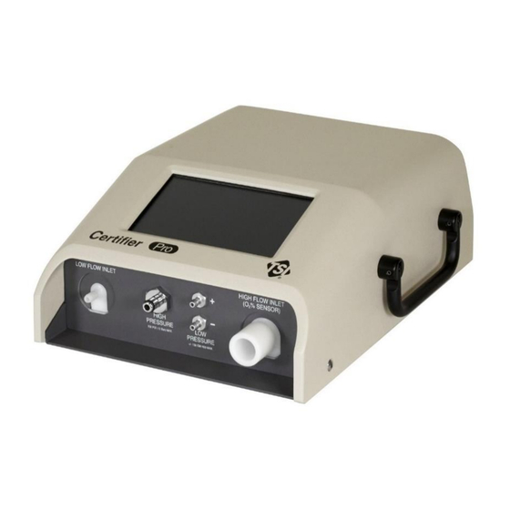
C H A P T E R 2 Flow Analyzer Overview I n s t r u m e n t O v e r v i e w Model 4090 Instrument, Front Low Flow Channel Inlet Low Differential Pressure, Positive Port (+) High Flow Channel Inlet Low Differential Pressure, Negative Port (-) High Pressure Port (Max: 150 psi / 10 bar) -
Page 14: Model 4090 Instrument, Bottom
Model 4090 Instrument, Bottom Battery/Oxygen Sensor Cover Rubber Feet Cover Knob Instrument Handle Cable Retainer Certifier™ Pro Flow Analyzer Test System... -
Page 15: Operation Overview
O p e r a t i o n O v e r v i e w Flow Channels Measurements from both flow channels are available for simultaneous use. You can connect or disconnect your test circuit to or from the Certifier™ Pro Flow Analyzer at any time during normal operation without having to reboot the instrument or change settings. -
Page 16: Touchscreen Display
If the Certifier™ Pro Flow Analyzer is turned off with the battery installed while connected to power via the power cable, the power button will display the following LED states: • Solid yellow: Battery is charging • Blinking yellow: Battery is full, no charging needed If no battery is installed and the Certifier™... -
Page 17: Portable/Rack Mode
Portable/Rack Mode In Portable mode, the instrument will run on battery power if no power is supplied. In Rack mode, the instrument will turn on when power is supplied and turn off when power is removed. NOTICE In Rack mode, the Certifier™ Flow Analyzer will not allow you to cancel the auto shutdown process if no power is supplied. -
Page 18: Available Units Of Measurement
Available Units of Measurement Measurement Factory Default Units Optional User-Selectable Units V , V L/min mL/min, mL/s PEAK , V, MV mL, L P, PIP, P Pa, kPa, mbar, PSI, inH mmHg Δ PLAT kPa, bar HIGH Pa, hPa, mbar, bar, PSI, cmH O, mmHg % oxygen 1/min... -
Page 19: Measurement Parameter Definitions
Measurement Parameter Definitions Flow Analyzer Overview... - Page 20 (This page intentionally left blank) Certifier™ Pro Flow Analyzer Test System...
-
Page 21: Chapter 3 Flow Analyzer Setup
C H A P T E R 3 Flow Analyzer Setup G e t t i n g S t a r t e d Power On/Off Press the power button located on the back of the Certifier™ Pro Flow Analyzer once to turn the instrument on. -
Page 22: Breath Triggers
Breath Triggers The Certifier™ Pro Flow Analyzer uses triggers to define start of the inspiratory and expiratory cycles. Triggers are based on the flow rate, pressure, or from a TTL voltage signal. The Certifier™ Flow Analyzer is set as its trigger default to automatically detect the breath cycles (using flow rate), but you can also set your own start and end trigger values. - Page 23 Ventilator Test circuit for bi-directional flow Flow Analyzer Overview...
-
Page 24: Pre-Test Checks
P r e - T e s t C h e c k s Flow Measurement To ensure proper operation of the system for safety, ensure the instrument’s flow calibration date is valid. If the calibration due date is approaching or past according to the factory attached label, return ®... -
Page 25: Chapter 4 Touchscreen Operation
C H A P T E R 4 Touchscreen Operation D i s p l a y I n t e r f a c e O v e r v i e w The two primary screens on the Dashboard of the Certifier™ Pro Flow Analyzer are the Parameter Screen and the Graph Screen. - Page 26 Option Description An “L” in the Low Flow channel card and an “H” is displayed in the High 3. Module Indicator Flow channel card. These letters correspond to the letters displayed for each measurement and are used to signal from which flow channel the readings are made.
-
Page 27: Warnings And Errors
Warnings and Errors Descriptions of any active warnings or errors can be viewed in the Active Warnings and Errors screen. Errors are shown highlighted in red, whereas warnings are not highlighted. You can clear warnings manually in this screen if desired. Errors can only be cleared if you take appropriate steps to resolve the error state or if the Certifier™... -
Page 28: Graph Screen
Graph Screen 1. Plotted Measurements 4. Trigger Indicators 2. Y-Axis 5. Real-time Measurements 3. X-Axis 6. Edit Graph Option Description 1. Plotted Displays current values for the selected measurements and their units and Measurements plots the measurement on the graph. You can graph up to two measurements at a time. -
Page 29: Channel Cards
Channel Cards A card is shown in the black header bar for both the high flow and low flow channels. Upon pressing a channel card, you will be able to edit gas type or gas condition settings for that particular module. Gas Type options available on the Certifier™... -
Page 30: Menu Screen
Menu Screen The menu can be accessed from either the Parameter screen or Graph screen. Menu Description Dashboard Closes the Menu options and returns you to the previous screen. Manage Data Enters screen where you can organize, preview, export, and delete saved data. - Page 31 Press the (+) ADD tile to select an additional measurement, or press the measurement symbol of a currently selected measurement to change that measurement parameter. Once pressed, a list of available measurements will be displayed in alphabetical order (see below left). An H is displayed in the upper left to indicate the measurement is coming from the High flow channel, and an L is displayed for measurements coming from the Low flow channel.
-
Page 32: Gas Type And Gas Condition
To remove a measurement from being displayed on the Parameter screen, press the X located next to the units for that measurement. Press the orange X button in the right navigation bar at any time to disregard all changes and return to the Parameter screen. -
Page 33: Breath Triggers
Gas condition options available on the Certifier™ Flow Analyzer: Option Description Actual Temperature and Pressure. The gas flow rate and volumes at the actual temperature and pressure of the gas. ATP is the default gas condition for the Certifier™ Flow Analyzer. Standard Temperature and Pressure. - Page 34 Flow Rate – Manual Triggers If auto-triggering is not providing reasonable results, consider using manual flow triggering. Press the Auto Trigger box to unselect it and be able to specify flow rate values for the start and end of the breath.
-
Page 35: Averaging
Averaging Access the Averaging screen by pressing on the area around the Breaths and Averaging Time fields or gear icon located at the bottom of the screen. Averaging can also be accessed through the Menu by selecting Settings and then the Triggers and Averaging option. Number of Breaths This setting specifies the maximum number of breaths over which to average the breathing parameter measurements. -
Page 36: Managing Configurations
NOTICE An asterisk will be displayed in front of the configuration name to indicate that the settings have been changed and differ from what is saved in the original configuration. The asterisk will be removed if the Certifier™ Flow Analyzer is changed back to the original configuration settings or if the configuration is reloaded. -
Page 37: Loading Configurations
The check boxes are used to select multiple files so you may export or delete more than one configuration at a time. Press a check box to select and press again to deselect. Press the checkbox in the Name column heading to select all configuration files. NOTICE The Default configuration file cannot be overwritten, renamed, exported, or deleted. -
Page 38: Saving Configurations
Saving Configurations To save the current Certifier™ Pro Flow Analyzer setup as a configuration, navigate to the Local tab of the Configurations screen and click the save (disk) icon. A pop-up screen provides the options to overwrite the active configuration [SAVE] or to create a new configuration [NEW]. NOTICE Only one configuration file can be saved at a time, the check boxes are not used for saving configurations. -
Page 39: Exporting Configurations
Exporting Configurations Configurations are stored in the internal memory of the Certifier™ Pro Flow Analyzer and can be exported from either of the two USB-A ports located on the back of the instrument. To export one or more configurations, insert a USB flash drive into the Certifier™ Flow Analyzer and navigate to the Local tab of the Configurations screen. -
Page 40: Importing Configurations
Importing Configurations The Certifier™ Pro Flow Analyzer can import configurations from a USB flash drive inserted into either of the two USB-A ports located on the back of the instrument. The Certifier™ Flow Analyzer will recognize any configuration files and display them in the External Configurations tab. To import a single configuration, either click on the 3-dot menu of that particular configuration file and select the Import menu option, or check the corresponding box and press the export icon (down arrow). -
Page 41: Plotted Measurements
Plotted Measurements Either 1 or 2 measurements can be plotted on the graph at a time. The primary measurement is displayed on the left side of the screen and the secondary measurement on the right. The color of the borders around the plotted measurements in the edit screen correspond to the colors shown for the Y-axes and traces on the graph. -
Page 42: Y-Axis Scaling
Y-Axis Scaling Scaling for the Y-axis is displayed in the same units as those selected for the plotted measurement. The color of the borders around the Y-Axis Scales in the edit graph screen correspond to the colors shown for the Y-axes and traces on the graph. The Y-axis is set to scale automatically as the default. -
Page 43: Trigger Timing
The Span option does not count the time and retains the beginning and end of the display span. For example, with the Span option selected and a display span of 15 seconds, the graph will show 00:00:00 as the minimum and 00:00:15 as the maximum for the X-axis. Trigger Timing When enabled, the trigger timing being used by the Certifier™... -
Page 44: Zeroing And Calibration
To change the units of measurement for a parameter, press on the currently selected units to access a drop-down list of available alternatives (see below right). Refer to the table Available Units of Measurement to see all the available units for each measurement. To reorder the selected real-time measurements, press and hold a measurement tile to be able to drag it left or right along the bottom of the display. -
Page 45: Calibrate Oxygen Sensor
2. Press the zero icon located in the right navigation bar of the Certifier™ display (see below right). 3. Select the sensor(s) to be zeroed by checking their boxes and press the Zero Selected button, or press the Zero All button to select and zero all pressure sensors. After zeroing, a status is displayed for each pressure sensor to indicate the result of the zero process. -
Page 46: Set Installation Date
3. In the Oxygen Sensor screen, the Certifier™ Flow Analyzer will display any connected oxygen sensors. Press the Calibrate button and follow the on-screen directions to complete the calibration process. Note that either an “air only” or “air and 100% oxygen” calibration can be done. -
Page 47: Data Logging And Export
D a t a L o g g i n g a n d E x p o r t The Certifier™ Pro Flow Analyzer is capable of logging measurement data and capturing screenshots. Files are saved to the internal memory of the Certifier™ Flow Analyzer and can be exported through either of its two USB-A ports. - Page 48 NOTICE After pressing the SAVE button, the Certifier™ Flow Analyzer will return to the previous screen with the display still paused. Press the Play button (triangle icon) in the right navigation bar to resume updating the display. Pressing the CANCEL button from the Data Save screen will return you to the previous screen and automatically resume updating the display.
- Page 49 Waveform Logging Waveform logging is used to record raw sensor data with high resolution. Waveform logs include data for flow rate, low pressure, high pressure, absolute pressure, temperature, and oxygen concentration (if connected) regardless of the screen from which logging was initiated. The sampling rate for waveform logging is fixed at 1 ms (1000 Hz).
-
Page 50: Managing Data
Managing Data Saved screenshots and data log files are stored in the internal memory of the Certifier™ Pro Flow Analyzer and can be viewed from the Manage Data screen. Access the Manage Data screen by pressing the Menu and selecting the Manage Data menu option. From this screen you can preview, export, or delete screenshots and saved files. - Page 51 Preview Saved Files You can preview screenshots and data logs from the Certifier™ Pro display prior to exporting. To do this, press anywhere on the row of the file you want to view. In the File Preview screen, you can preview screen captures or logged data in graph form. For data log files, the preview screen displays the number of data points collected, log start time, total logging time, sampling rate, the active configuration, comments, and the module from which the data came from.
-
Page 52: Exporting Data
Press on the image in the File Preview screen to increase its size for easier viewing. Press on the image again to return the expanded image to its original size. Delete Saved Files In the Manage Data screen, use the check boxes to select one file or multiple files. Press a check box to select and press again to deselect. -
Page 53: Viewing Exported Data
While actively exporting files, a loading icon will appear and the export progress is shown in the bottom screen bar. The Certifier™ Flow Analyzer will provide notification when the export has completed. Snapshots are exported as .png image files and data is exported as .csv files. The delimiter for data export can be set as comma, pipe, semicolon, or tab delimited. -
Page 54: Device Settings
D e v i c e S e t t i n g s Access the device settings by choosing the Settings option from the Menu drop-down. From this screen, you can select which functional settings to view and adjust. General Settings In this screen you can set the Export Delimiter and Decimal format for the Certifier™... -
Page 55: Display/Power Management
Display/Power Management You can adjust the display brightness to your preferred brightness including dimming the brightness in order to conserve power. Press on the gray scroll bar or drag the blue circle indicator to set the brightness level. Flow Channel Power Toggles The default mode for the Certifier™... -
Page 56: Device Information
D e v i c e I n f o r m a t i o n The device information screen displays information about the Certifier™ Pro instrument. Access this screen by selecting the Device Information option from the menu drop-down. The Version field lists the firmware version currently implemented for the Certifier™... -
Page 57: Chapter 5 Troubleshooting
C H A P T E R 5 Troubleshooting The table below lists the symptoms, possible causes, and recommended corrective actions for problems that may be encountered while operating the Certifier™ Pro system. If the symptom is not listed or if none of the recommended corrective actions solve the problem, contact technical support at technical.services@tsi.com or customer support at 800-680-1220 or 651-490-2860 for assistance. - Page 58 Symptom Possible Cause Corrective Action Oxygen sensor 21% oxygen and/or 100% Verify that calibration gases are calibration fails. oxygen not supplied for 21% and 100% O and repeat calibration. Oxygen sensor is calibration. Replace oxygen expired. Non-steady flow or sensor. Use constant flow rates tidal flows used.
-
Page 59: Chapter 6 Maintenance
C H A P T E R 6 Maintenance R e c h a r g i n g t h e B a t t e r y The fastest charging method is to charge the internal batteries with the Certifier™ Pro Flow Analyzer Test System turned off. -
Page 60: Battery Calibration
To install a battery into the Certifier™ Pro Flow Analyzer: • Turn the Certifier™ instrument off and disconnect any cables. • Remove the back plate and plug the battery pigtail connector into the Certifier™ Pro Flow Analyzer. • Lift the retainer plate and insert the battery pack underneath, secure plate with one (1) screw. •... -
Page 61: Replacing The Oxygen Sensor
R e p l a c i n g t h e O x y g e n S e n s o r The oxygen sensor will function for one or more years of normal operation if use begins before the expiration date. -
Page 62: Factory Calibration (Recommended Annually)
• Package the Certifier™ Pro Flow Analyzer carefully to avoid damage during shipping. Please note that it is not necessary to return accessories for calibration service. TSI Instruments Singapore Pte Ltd TSI Incorporated 150 Kampong Ampat 500 Cardigan Road... -
Page 63: Chapter 7 Specifications
C H A P T E R 7 Specifications Specifications are subject to change without notice. P h y s i c a l Dimensions ....... Instrument: 11 x 8.3 x 4.5 inches Flow connectors ....... High Flow Channel: • Inlet: 22 mm female ISO taper •... -
Page 64: Measurements
M e a s u r e m e n t s See additional notes listed at the end of the specifications. Measurement High Flow Channel Low Flow Channel V , V Flows PEAK Range -200 to +300 SLPM for air, oxygen, 0.01 to 20 SLPM for air, oxygen, and nitrogen nitrogen, carbon dioxide, and... - Page 65 Measurement High Flow Channel Low Flow Channel High Pressure High Range -10 to 150.0 psig Accuracy ±1% of reading or 0.1 psi, whichever is greater Absolute Pressure Range 50 to 200 kPa 50 to 200 kPa Accuracy ±0.7% kPa ±0.7% kPa Static Compliance Stat Range...
-
Page 66: Certifier™ Pro Flow Analyzer Pressure Drop
C e r t i f i e r ™ P r o F l o w A n a l y z e r P r e s s u r e D r o p Low Flow Channel High Flow Channel Certifier™... -
Page 67: Appendix A Data Export Formats
A P P E N D I X A Data Export Formats S n a p s h o t D a t a F i l e f r o m t h e P a r a m e t e r S c r e e n NOTICE Snapshots initiated from the Parameter screen capture a single data point of the current reading for all measurements selected on the Parameter screen. -
Page 68: Continuous Log File (Initiated From The Parameter Screen Or Graph Screen
C o n t i n u o u s L o g f i l e ( I n i t i a t e d f r o m t h e P a r a m e t e r S c r e e n o r G r a p h S c r e e n ) Certifier™... -
Page 69: Waveform Log File (Initiated From The Parameter Screen Or Graph Screen
W a v e f o r m L o g f i l e ( I n i t i a t e d f r o m t h e P a r a m e t e r S c r e e n o r G r a p h S c r e e n ) NOTICE The cells in the “Time”... - Page 70 (This page intentionally left blank) Certifier™ Pro Flow Analyzer Test System...
- Page 72 TSI Incorporated – Visit our website www.tsi.com for more information. Tel: +1 800 680-1220 India Tel: +91 80 67877200 Tel: +44 149 4 459200 China Tel: +86 10 8219 7688 France Tel: +33 1 41 19 21 99 Singapore Tel: +65 6595 6388 Germany Tel: +49 241 523030 P/N 6016808 Rev A ©2023 TSI Incorporated...
Need help?
Do you have a question about the Certifier 4090 and is the answer not in the manual?
Questions and answers