Table of Contents
Advertisement
Quick Links
THE FLOWMASTER 250DL MEASURES THE FLOW RATE AND THE PRESSURE AT
EvERy WATER DRAWING OFF POINT AND PRODUCES vERIFIABLE REPORTS
OPERATION
MANUAL
AND
MAINTENANCE
MANUAL
MODEL Flowmaster 250DL
Unit 1, Portlaoise Enterprise Centre, Clonminam Industrial Estate, Portlaoise, Co. Laois, Ireland
t: +353 (0)87 235 2107 | f: +353 (0)57 866 3852 | e: info@tsi.ie
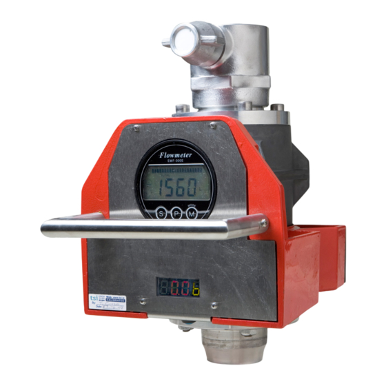
FLOWMASTER 250DL
PORTABLE FLOW & PRESSURE TEST
INSTRUMENT WITH DATA LOGGER
Easy and simple to use everywhere
www.tsi.ie
Advertisement
Table of Contents

Related Manuals for TSI Instruments Flowmaster 250DL


Summary of Contents for TSI Instruments Flowmaster 250DL
- Page 1 FLOWMASTER 250DL PORTABLE FLOW & PRESSURE TEST INSTRUMENT WITH DATA LOGGER Easy and simple to use everywhere THE FLOWMASTER 250DL MEASURES THE FLOW RATE AND THE PRESSURE AT EvERy WATER DRAWING OFF POINT AND PRODUCES vERIFIABLE REPORTS OPERATION MANUAL MAINTENANCE...
- Page 2 OPERATION MANUAL MAINTENANCE MANUAL MODEL Flowmaster 250DL Digital Pressure and integrated Data Logger Version 2.0 February 2012 Unit 1, Portlaoise Enterprise Centre, Clonminam Industrial Estate, Portlaoise, Co. Laois, Ireland t: +353 (0)87 235 2107 | f: +353 (0)57 866 3852 | e: info@tsi.ie...
-
Page 3: Table Of Contents
CONTENTS GETTING TO KNOW yOUR MAINTENANCE & TROUBLE-SHOOTING FLOWMASTER 5.1 BATTERY MAINTENANCE 1.1 INTRODUCTION 5.2 FLOWMASTER MAINTENANCE 1.2 FOUR SIMPLE STEPS TO FAST FLOW ANALYSIS 5.3 TROUBLE-SHOOTING 1.3 APPLICATIONS 5.4 CALIBRATION OF YOUR FLOWMASTER 1.4 EXPLANATION OF USER PANEL 5.5 RESETTING THE CALIBRATION DUE DATE IN DATA LOGGER MEMORY SPECIFICATION 2.1 GENERAL... -
Page 4: Getting To Know Your Flowmaster
GETTING TO KNOW yOUR FLOWMASTER 1.1 INTRODUCTION FOUR SIMPLE STEPS TO FAST FLOW ANALySIS The model Flowmaster 250DL portable flow and pressure tester measures the available pressure and flow at the service point while recording the measurement points in the internal data logger for the creation of verifiable reports. -
Page 5: Applications
1.3.5 USING THE FLOWMASTER TO CONTROL 1.3 APPLICATIONS FLOW vELOCITy DURING FLUSHING. Our fire service customers use the Flowmaster to test hydrants and fire fighting equipment such as pumps, hoses, dry risers and branches. Customers from the water services use the Flowmaster when flushing to regulate the flow rate and to measure the volume discharged for use in leakage figure calculations. -
Page 6: Specification
Flowmaster: • Operation and Maintenance Manual • Software Manual PRESSURE TRANSDUCER AND DISPLAy • You Tube videos demonstrating how to use the Flowmaster 250DL Type • You Tube videos demonstrating how to use the flow Strain Gauge Range monitoring software supplied with the Flowmaster 0 ~ 25 bar, ±1%. -
Page 7: Flowmaster Operation
FLOWMASTER OPERATION The Flowmaster is ready to measure flow and pressure 3.1 FLOWMETER POWER ON SEQUENCE as soon as battery power is applied. Turn on the Flowmaster by pressing the ON/OFF switch to “1” position. The Flow meter backlight LEDs will turn on. After a few moments, the self-test mode will commence Following power_on, the flow meter begins a self test and the display sequence will be as shown below. -
Page 8: Totaliser Function
TOTALISER FUNCTION PRESSURE READOUT POWER ON SEQUENCE The flow meter has a built in totalising function. The volume of water that has passed through the flow meter is totaled and and stored in internal memory. Put the meter readout into totaliser mode by pressing the M (mode) switch once. -
Page 9: Using Your Flowmaster
UXd3Mk • Using the Flowmaster 250 to test a Canadian Hydrant (Hetek) - http://www.youtube.com/watch?v=a19GwFK kT9w&feature=player_embedded • Using the Flowmaster 250DL to test a Hydrant and generate a report - http://www.youtube.com/ watch?v=IQaSS3JHfdA • Data Logging and Reviewing Test Data with FMS Software - http://www.youtube.com/watch?v=InR3rB1m... -
Page 10: Precautions
4.1 PRECAUTIONS IMPORTANT – PLEASE READ THIS SECTION BEFORE USING yOUR FLOWMASTER. It is important to think safety first, especially when working with pressure. Please ensure the Flowmaster is securely attached to the service fitting (eg, hydrant outlet, pump, etc) before pressurizing. -
Page 11: Static Pressure Measurement
4.3 STATIC PRESSURE MEASUREMENT 4.4 FLUSHING 1) Equipment required for flushing. 1) Attach Flowmaster to standpipe. 2) Attach blank plug. Ensure bleed valve is open. 3) Crack open the hydrant slowly. All air will be expelled from the standpipe when water begins to drain from the bleed valve. -
Page 12: Using The Data Logger
4.5.1 ESTABLISHING THE LOGGING PARAMETERS 4.5 USING THE DATA LOGGER Connect your Flowmaster to your PC using the USB cable provided. Start up the Flow Monitoring software and the window shown in Fig. 4.7 will appear. Click on the Device Settings button at the bottom of the window to access the menu where data logging parameters can be established. - Page 13 The text ‘Downloaded - downloading new settings successfully’ will appear as shown in Fig. 4.13. The Flowmaster 250DL is shipped with current date and time (GMT) set and with a sample interval of one second. Automatic triggering is enabled as default setting.
- Page 14 In manual mode, please press the black switch located at of the Flowmaster 250DL. These error messages are as the control panel of the Flowmaster to the ‘1’ position set out in Table 1.
- Page 15 4.5.3 UPLOADING yOUR DATA Uploading your data couldn’t be simpler. Connect the mini-USB cable to the data interface socket on the Flowmaster control panel - (Unscrew the dust cap beforehand) – and connect the other end of the cable to an unused USB socket on your computer. Start up the application, ‘TSI Flow Monitoring’, click on the data upload button and all your files will be uploaded to your computer.
-
Page 16: Maintenance & Trouble-Shooting
The flow meter control electronics are in a waterproof BATTERy LIFE compartment located beneath the display gauge. Please The type of battery in use on the Flowmaster 250DL do not open this compartment. Breaking the seal will is lead acid type. This battery type is designed for destroy the water-proof feature of this compartment regular but intermittent use. -
Page 17: Trouble-Shooting
Possible Cause: and about the status of the Flowmaster 250DL. These The Sensor part of the device and the Display part of messages are as set out in Table 1 below. -
Page 18: Calibration Of Your Flowmaster
5.3.6 ALL LOG FILE DATES ARE yEAR 2000 5.4 CALIBRATION OF yOUR FLOWMASTER The data logger has a rechargeable battery to power flash memory within the data logger. If this battery has Every TSI flow meter is tested and calibrated prior to no charge, the date will revert to the default date of shipping. -
Page 19: Resetting The Calibration Due Date In Data Logger Memory
5.5 RESETTING THE CALIBRATION DUE DATE • The calibration due date has now been updated and IN DATA LOGGER MEMORy the reminder messages will no longer appear on the LED readout of the Flowmaster. Reminders that the meter calibration is due or is out are provided on the LED readout for your convenience. - Page 20 TSI will send you a new code in a document that can be read in Notepad or in MS word. The code format is as shown. fd0f77da907e865ac74f29f45efcb76a Fig. 5.16 Error message if incorrect key To apply your new code, follow the procedure outlined from Fig.
-
Page 21: Stage Battery Chargers
GENERAL INSTRUCTION: CM RANGE 3 STAGE BATTERy CHARGERS Proportional Charging – Automatically, 6.1 OvERvIEW proportionally adjusts the second (constant voltage) stage length of charge based on the time taken to This new range of battery chargers utilises the latest carry out the first (constant current) stage. This facility computer controlled technology designed to give allows optimal charging by eliminating overcharging and greater charging control of Lead Acid batteries, with... -
Page 22: Accessories
ACCESSORIES We can also supply to ¾” BSP male, 1” BSP male, 4” 7.1 BALL vALvE WITH BS INST. M/F FITTINGS BSP male as standard items. These adaptors are tapered so as to minimize turbulence and fluid restriction, The ball valve facilitates speedy and safe static pressure thereby ensuring minimum interruption to fluid flow readings and creates back pressure for taking flow and and accurate measurements. -
Page 23: Limited Warranty
LIMITED WARRANTy TSI Flowmeters Ltd., of 24 Rockdale, Mountrath Road, warranty or otherwise. Portlaoise, Co. Laois, Ireland (Warrantor), warrants to the original purchaser of the new fire protection WARRANTOR EXPRESSLY LIMITS WITH RESPECT equipment manufactured by Warrantor and to any TO SUCH EQUIPMENT ALL IMPLIED WARRANTIES person to whom such equipment is transferred, that MERCHANTABILITY... -
Page 24: Ce Declaration Of Conformity
CE DECLARATION OF CONFORMITy Version 2.0 (February 2012) TSI Flowmeters Ltd. -
Page 25: Calibration Certificate
10 CALIBRATION CERTIFICATE Certificate of Calibration Issued by: TSI Flowmeters Ltd 24 Rockdale, Mountrath Road, Portlaoise, Co. Laois, Ireland. Tel: 087-235-2107 Email: info@tsi.ie The readings obtained by the Test Equipment referred to on this certificate are traceable to National and International standards. Calibration Cert No. 6825CN. Cert No.
Need help?
Do you have a question about the Flowmaster 250DL and is the answer not in the manual?
Questions and answers