
Related Manuals for TSI Instruments PANDA LIGHT


Summary of Contents for TSI Instruments PANDA LIGHT
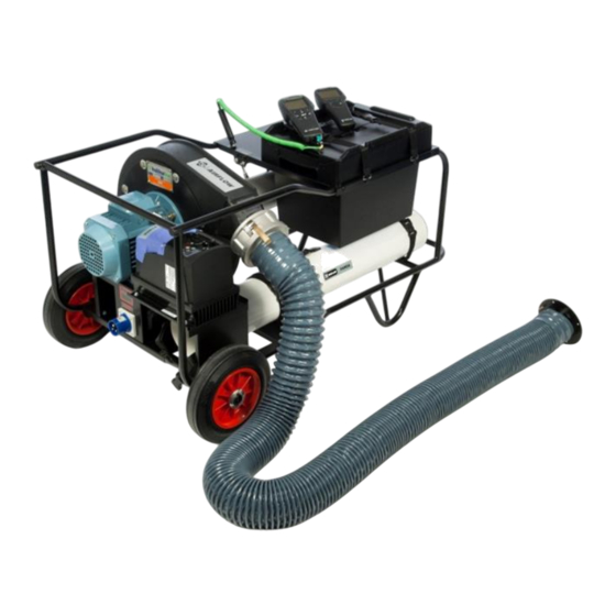
- Page 1 POSITIVE AND NEGATIVE DUCT ACCREDITATION (PANDA) SYSTEM AIRFLOW INSTRUMENTS ™ MODEL PAN341 SERIES (PANDA LIGHT) OPERATION AND SERVICE MANUAL P/N 6006694, REV D JULY 2017...
- Page 3 Copyright© TSI Incorporated / 2011-2017 / All rights reserved. Address TSI Incorporated / 500 Cardigan Road / Shoreview, MN 55126 / USA Fax No. (651) 490-3824 Limitation Of Warranty And Liability (effective February 2015) (For country-specific terms and conditions outside of the USA, please visit www.tsi.com.) Seller warrants the goods, excluding software, sold hereunder, under normal use and service as described in the operator's manual, to be free from defects in workmanship and material for 24 months, or if less, the length of time specified in the operator's...
- Page 4 SELLER WILL REPAIR OR REPLACE DEFECTIVE SOFTWARE OR IF UNABLE TO DO SO, WILL REFUND THE PURCHASE PRICE OF THE SOFTWARE. IN NO EVENT SHALL SELLER BE LIABLE FOR LOST PROFITS, BUSINESS INTERRUPTION, OR ANY SPECIAL, INDIRECT, CONSEQUENTIAL OR INCIDENTAL DAMAGES. SELLER SHALL NOT BE RESPONSIBLE FOR INSTALLATION, DISMANTLING OR REINSTALLATION COSTS OR CHARGES.
-
Page 5: Table Of Contents
CONTENTS CHAPTER 1 UNPACKING AND PARTS IDENTIFICATION ..... 1 CHAPTER 2 PREPARING PAN341 SYSTEM FOR AIR DUCT LEAK TESTING ................... 5 CHAPTER 3 PERFORMING A DUCT LEAKAGE TEST ....11 Measuring Duct Static Pressure ........... 11 Measuring Duct Leakage Flow ............. 12 Turning on the PAN341 Duct Leakage Tester...... - Page 6 (This page intentionally left blank)
-
Page 7: Chapter 1 Unpacking And Parts Identification
Chapter 1 Unpacking and Parts Identification Carefully unpack the PANDA system and instrument cases from the shipping container. Check the individual parts against the list of components below. If anything is missing or damaged, notify TSI immediately. The PANDA system consists of the following: Description Part Number Reference Picture... - Page 8 Description Part Number Reference Picture 20-in. (500-mm) AFL9020005 silicone tubes (blue) 16-ft (5-m) silicone tube AFL9020005 (blue) K-type thermocouple AFL82859201 probe Instrument adapter AFL82859401 Instrument Box 6006490 Flex Duct Carry Tube 6006491 Operation and Service 6006694 manual Chapter 1...
- Page 9 The following two instruments should be used in conjunction with the PANDA unit: TA465-P Multi-function Refer to TA465 Operation and Instrument Service Manual supplied with the instrument for additional parts supplied as standard. PVM610 Refer to PVM610 Operation and Micromanometer Service Manual supplied with the instrument for additional parts supplied as standard.
- Page 10 PANDA Models Model Description PAN315 220/240V, instruments not included PAN315-110 110/120V, instruments not included PAN341 PAN315 with instruments PAN341-110 PAN315-110 with instruments Chapter 1...
-
Page 11: Chapter 2 Preparing Pan341 System For Air Duct Leak Testing
Chapter 2 Preparing PAN341 System for Air Duct Leak Testing Carefully follow the procedures below to achieve safe and accurate leakage testing: Successfully completing a duct leakage test requires compiling certain information prior to starting the test. Refer to Appendix B for a discussion of standards relating to duct leakage testing. - Page 12 C A U T I O N Remove the power cord from the PANDA duct leakage tester before tilting it to the vertical position to avoid damaging the cord. Figure 1. Fan Speed Controller The settings for the inverter have been locked and cannot Note: be changed using the key pad.
- Page 13 6. Fit the primary duct adapter spigot (black sheet metal with rubber bung) to one end of the 4-in. (100-mm) diameter flexi- tube. Make an air-tight seal using one of the over lock straps and lever-locking cam provided as shown in Figure 4. Adjust the fit of the over lock strap with a screwdriver.
- Page 14 10. Determine if you are going to perform a high- or low-flow testing and positive or negative testing. Set-up the duct leakage tester by: a. For positive pressure, high- flow testing, remove the low flow nozzle if it is installed. Then, connect the grey cast-aluminum cam lock connector to the outlet side of the blower...
- Page 15 c. For negative pressure, high-flow testing, remove the low flow nozzle if it is installed. Then, connect the grey cast aluminum cam lock connector to the inlet side of the blower per Figure 8. Close both cam lock arms at the same time Cam Lock Fan Inlet to ensure proper fit.
- Page 16 (This page intentionally left blank) Chapter 2...
-
Page 17: Chapter 3 Performing A Duct Leakage Test
Chapter 3 Performing a Duct Leakage Test The PAN341 duct leakage test system includes a Model PVM610 Micromanometer and a Model TA465-P Ventilation Meter. During duct leakage testing, the Model PVM610 Micromanometer measures the duct static pressure while the Model TA465-P Ventilation Meter measures the airflow rate. -
Page 18: Measuring Duct Leakage Flow
Measuring Duct Leakage Flow 1. Turn ON Model TA465-P. P1(+) and P2(-) Flow Grid Pressure Connections 2. Zero the Model TA465-P pressure sensor with both ports open to the atmosphere. 3. Connect the Model TA465-P to the PAN341 by connecting the (+) and (-) ports on the Model TA465-P to the P1 (+) and P2 (+) ports located on the inside... - Page 19 1. Press the MENU key to access MENU the menu system on the Zero Press Model TA465-P. Display Setup 2. Use the keys to highlight Settings the Applications item. Flow Setup 3. Press the (ENTER) key to Actual/Std Setup access the Applications menu.
- Page 20 d. Leakage class as A, B, C, or D. Note that tests with negative pressures must be selected as negative tests, as indicated by -. e. Test Length, or duration of leakage test, usually 5 minutes. 2. Increase the blower speed until LEAKAGE TEST the desired static pressure is Leakage Factor x.xx...
- Page 21 LEAKAGE TEST d. Leakage class as a number from 1 to 48. Typical values Leakage Factor x.xx are 2, 4, 8, or 16. Leak Limit x.xx Leak Rate x.xx e. Test Length, or duration of Status leakage test. Flow Device Flow Grid 2.
-
Page 22: Troubleshooting Guide
Troubleshooting Guide Symptom Recommended Action Check the power connection. Fan motor will not run. Circuit Breaker may have tripped. Check the connections. Static pressure reading (on PVM610) is zero. Leakage rate is too high. Static pressure reading (on PVM610) is too low. -
Page 23: Appendix A Specifications
Appendix A Specifications Pressure Measurement (PVM610) Range ± 3,735 Pa ±15 inwg Resolution 0.1 Pa 0.001 inwg Accuracy ±1% of reading ±1% of reading ±1 Pa ±0.005 inwg Actual duct static range 2500 Pa at 0 Flow 10 inwg at 0 Flow Volume Flow Measurement (TA465-P) High Leakage Range 10 to 200 l/s... - Page 24 Power Requirements 230V Version 220 to 240 V, 1 Phase, 50/60 Hz 10A 110V Version 110 to 120 V, 1 Phase, 50/60 Hz 16A TA465-P and PVM610 See specification sheets for details on individual instruments (Specifications are subject to change without notice.) Appendix A...
- Page 25 Panda Fan Performance Graph (metric units) 3000 2500 2000 1500 1000 Volume Flow l/s Specifications...
- Page 26 Panda Fan Performance Graph (imperial units) Volume Flow CFM Appendix A...
-
Page 27: Appendix B Leakage Testing Standards Highlights
Appendix B Leakage Testing Standards Highlights Different standards are used throughout the world to specify duct air tightness and leakage requirements. The PAN341 duct leakage test system has a duct leakage application to automatically compare the actual leakage flow with the maximum allowed leakage flow for EN and SMACNA standards. -
Page 28: Eu Standards
EU Standards Ductwork classification and maximum air leakage. Note that EN1507, EN12237 Eurovent 2/2 and DW/143 all have the same formula to determine f , the Air Leakage Limit, although DW/143 uses units of l/s/m whereas others use m /s/m ... - Page 29 DW/143: A Practical Guide to Ductwork Leakage Testing Static Pressure Maximum Limit Duct Air leakage Pressure Positive Negative Velocity limits Class l/s/m 0.65 Low-pressure 0.027*p – Class A 0.65 Medium- 1000 0.009*p pressure – Class B 0.65 High pressure 2000 0.003*p –...
- Page 30 The test report shall give the following general information of the test performed: Date and place Test personnel and witness Test equipment, including pressuring means and measuring instruments Air temperature and barometric pressure during the test Building and project reference Design of installed ductwork including dimensions, thickness of materials, types of stiffening, length, type of duct/tubes and fittings, assembly method and distance of hangers/supports...
-
Page 31: Us Standards
US Standards Ductwork classification and maximum air leakage Duct Class ½-, 1-, 2-in wg 3-in wg 4-, 6-, 10-in wg Seal Class Transverse Joints, Seams and Sealing Transverse Joints and All Applicable Wall Applicable Joints Only Seams Penetrations Leakage Class Rectangular Metal Round... - Page 32 Figure 13. Allowable Air Duct Leakage from Rectangular Ducts, per SMACNA Standard The SMACNA standard does not generally require correcting leakage flow rates to standard conditions, unless: 1. Air temperature <40ºF or >100ºF 2. Elevation <1500 ft above sea level 3.
- Page 33 The SMACNA standard does not specify the information to be reported, but instead defers to project documents. However, the SMACNA standard does include a sample test report that includes: Test date and place Test personnel and witness Building and project reference Duct section tested Specified leakage class, test pressure and duct construction pressure class...
- Page 34 (This page intentionally left blank) Appendix B...
-
Page 35: Appendix C Typical Setup
Appendix C Typical Setup... - Page 36 (This page intentionally left blank) Appendix C...
- Page 37 Airflow Instruments, TSI Instruments Ltd. Visit our website at www.airflowinstruments.co.uk for more information. Tel: +44 149 4 459200 Germany Tel: +49 241 523030 France Tel: +33 1 41 19 21 99 P/N 6006694 Rev D ©2017 TSI Incorporated Printed in U.S.A.
Need help?
Do you have a question about the PANDA LIGHT and is the answer not in the manual?
Questions and answers