
Related Manuals for TSI Instruments Certifier Plus


Summary of Contents for TSI Instruments Certifier Plus
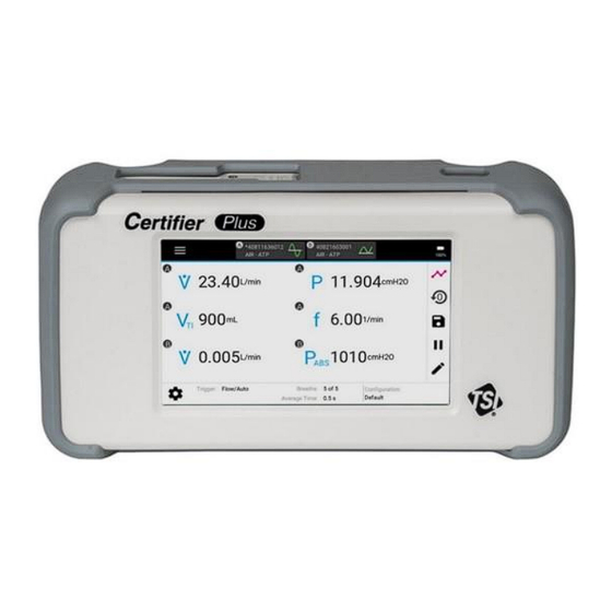
- Page 1 ™ Certifier Plus Flow Analyzer Test System Models 4089, 4081, 4082 User Manual P/N 6016477, Revision E May 2023 www.tsi.com...
- Page 2 Start Seeing the Benefits of Registering Today! ® ® Thank you for your TSI instrument purchase. Occasionally, TSI releases information on software updates, product enhancements ® and new products. By registering your instrument, TSI will be able to send this important information to you. http://register.tsi.com As part of the registration process, you will be asked for your comments on TSI products and services.
-
Page 3: Warranty
Warranty Copyright TSI Incorporated / 2022 / All rights reserved. Address TSI Incorporated / 500 Cardigan Road / Shoreview, MN 55126 USA W A R N I N G ® Certifier Flow Analyzers employ a heated platinum sensor. They SHOULD NOT be used with flammable or explosive gases or mixtures. - Page 4 TO THE EXTENT PERMITTED BY LAW, THE EXCLUSIVE REMEDY OF THE USER OR BUYER, AND THE LIMIT OF SELLER'S LIABILITY FOR ANY AND ALL LOSSES, INJURIES, OR DAMAGES CONCERNING THE GOODS (INCLUDING CLAIMS BASED ON CONTRACT, NEGLIGENCE, TORT, STRICT LIABILITY OR OTHERWISE) SHALL BE THE RETURN OF GOODS TO SELLER AND THE REFUND OF THE PURCHASE PRICE, OR, AT THE OPTION OF SELLER, THE REPAIR OR REPLACEMENT OF THE GOODS.
-
Page 5: Table Of Contents
Contents Warranty ................................iii Contents ................................v CHAPTER 1 Introduction and Parts Identification ................... 1-1 Introduction ............................1-1 Interface Module ..........................1-1 High Flow Module ..........................1-1 Low Flow Module ..........................1-1 Oxygen Sensor ..........................1-1 List of Standard Components ....................... 1-2 Certifier™... - Page 6 Connect the Oxygen Sensor ......................3-2 Breath Triggers ..........................3-2 Connect the Certifier™ Plus High Flow Module to a Ventilator ............3-3 Connecting the Low Flow Module ......................3-5 Pre-Test Checks ........................... 3-5 Low Flow Module ..........................3-5 High Flow Module ..........................3-5 Flow Module Self-Check ........................
- Page 7 CHAPTER 6 Maintenance ..........................6-1 Recharging the Battery ......................... 6-1 Replacing the Battery ..........................6-1 Replacing the Oxygen Sensor ......................6-2 Cleaning the Flow Analyzer ........................6-2 Factory Calibration (recommended annually) ..................6-3 Return Procedure ..........................6-3 CHAPTER 7 Specifications .......................... 7-1 Physical ..............................
- Page 8 (This page intentionally left blank) Certifier™ Plus Flow Analyzer Test System viii...
-
Page 9: Chapter 1 Introduction And Parts Identification
Connected to the high flow module, the oxygen sensor enables the measurement of oxygen concentration as well as air and oxygen mixtures. The Oxygen Sensor kit (model 4073) is an optional accessory for the 4080-S Certifier Plus system standard kit, but it is included as part of the model 4080-F system full kit. -
Page 10: List Of Standard Components
L i s t o f S t a n d a r d C o m p o n e n t s Carefully unpack the test system components from the shipping container. Check the individual parts ® against the packing list and notify TSI immediately if any parts are missing or damaged. -
Page 11: Certifier™ Plus High Flow Test System, Full Kit (Model 4080-F)
Certifier™ Plus High Flow Test System, Full Kit (Model 4080-F) Item Replacement Number Description Part Number Qty. Interface Module 4089 High Flow Module 4081 Inlet Filter, HEPA, 22 mm x 22 mm M/F (for use with 4081) 1602341 Adapter, high pressure port 1611221 Adapter, 22 mm x 6 mm (to connect 4081 to Low Flow Filter) 1102091... -
Page 12: List Of Accessory Kits
L i s t o f A c c e s s o r y K i t s Certifier™ Plus Low Flow Module Kit (Model 4082) Item Description Part Number Qty. Low Flow Module 4082 Inlet Filter, HEPA, 3/8 to 1/2-inch barb, plus 1602342 3/8-inch tubing Coupling, 3/8-inch tube... -
Page 13: Mounting Kit, For Certifier™ Plus Interface And Flow Module (Pn 130399)
Mounting Kit, for Certifier™ Plus Interface and Flow Module (PN 130399) Item Description Part Number Quantity RAM Double Socket Arm 130371 RAM Tough-Claw Small Clamp Base with Ball 130372 Adapter Plate for Interface + Flow Module, sheet metal 227099 (Attach either a 4081 high flow or 4082 low flow module) Certifier™... -
Page 14: Other Optional Accessories
O t h e r O p t i o n a l A c c e s s o r i e s Description Part Number Image Deluxe Carrying Case, Fitted for the 130393 Certifier™ Plus Flow Analyzer (19 x 14.75 x 6.5 inches 48 x 37.5 x 16.5 cm) Test Lung, Adult, 1.0L, includes 130396... -
Page 15: Chapter 2 Flow Analyzer Overview
C H A P T E R 2 Flow Analyzer Overview I n s t r u m e n t O v e r v i e w 4089 Interface Module, Back 4089 Interface Module, Front Flow Module Connector (A) Screw hole for USB-C cable lock Flow Module Connector (B) Tilt Stand... -
Page 16: 4081 High Flow Module, Back
4081 High Flow Module, Back 4081 High Flow Module, Front Interface Module Connector Mounting Holes (threaded #8-32) Sensor Input Low Pressure Ports (± 150 cmH Connect to “+” port for airway pressure TTL Trigger Input High Pressure Port (150 PSIG, 10 bar) 4082 Low Flow Module Interface Module Connector Mounting Holes (threaded #6-32) -
Page 17: Operation Overview
Flow Modules when not in use. Lithium Ion Batteries The model 4089 Certifier Plus Interface Module utilizes a 4-cell lithium ion battery pack which can provide up to 8 hours of continuous operation from a full charge. The battery pack is calibrated and installed into the 4089 Interface Module at the factory. -
Page 18: Touchscreen Display
Up to 20 different user configurations can be stored in the internal memory of the 4089 Certifier Plus Interface Module and can be exported from either USB-A port on the 4089 to a USB mass storage device. -
Page 19: Measurements And Units
M e a s u r e m e n t s a n d U n i t s Available Measurement Parameters The list parameters available for selection is dependent on the model of the connected flow module. Symbol Description Symbol Description... -
Page 20: Available Units Of Measurement
Available Units of Measurement Measurement Factory Default Units Optional User-Selectable Units V , V L/min mL/min, mL/s PEAK mL, L , V, MV kPa, Pa, hPa, mbar, mmHg, P, PIP, P O, PSI Δ PLAT kPa, bar HIGH O, Pa, hPa, mbar, bar, mmHg, PSI, inH kPa/s, Pa/s, hPa/s, mbar/s, mmHg/s, PSI/s, inH... -
Page 21: Measurement Parameter Definitions
Measurement Parameter Definitions Flow Analyzer Overview... - Page 22 (This page intentionally left blank) Certifier™ Plus Flow Analyzer Test System...
-
Page 23: Chapter 3 Flow Analyzer Setup
Certifier instrument. C A U T I O N To avoid damage to the Certifier Plus Test System components, always use inlet filters upstream of the flow modules. -
Page 24: Connect The Low Pressure Measurement
Connect the Low Pressure Measurement Low pressure is available from the 4081 high flow module only. To connect the oxygen sensor kit, attach the airway pressure fitting with screen (1) to the outlet of the flow module. Cut a length of silicon tubing (2), connect one end of the tubing to the barb on the airway pressure fitting, and connect the other end of the tubing to the (+) port of the flow module. -
Page 25: Connect The Certifier™ Plus High Flow Module To A Ventilator
2. Connect an inlet filter to the upstream end of the Certifier™ Plus High Flow Module. 3. Connect the AC adapter to the DC power input of the Certifier Plus Interface Module. The battery will charge in the instrument when the AC adapter is plugged in. The instrument can also be operated on battery power without a wired power connection. - Page 26 9. Perform testing per the device manufacturer’s procedure (or other appropriate procedure). The manufacturer of the device under test will specify the testing requirements and pass/fail criteria. Test circuit for bi-directional flow NOTICE If using a test lung with a built-in restrictor or a separate restrictor, connect the airway pressure fitting with less than 15 cm length of the 22 mm tubing between the restrictor and the flow module.
-
Page 27: Connecting The Low Flow Module
C o n n e c t i n g t h e L o w F l o w M o d u l e The 4082 low flow module is used for testing flow in oxygen concentrators and other low flow devices. It is not designed for testing ventilators. -
Page 28: Flow Module Self-Check
Low-Pressure and High-Pressure Transducer Zeroing Check the low-pressure transducer zero and high pressure transducer zero by disconnecting the pressure tubing from the flow module before each pressure measurement after initial power up to ensure the most accurate readings. If the low or high pressure is not reading zero, perform the following steps to zero the transducers. -
Page 29: Chapter 4 Touchscreen Operation
C H A P T E R 4 Touchscreen Operation D i s p l a y I n t e r f a c e O v e r v i e w The two primary screens on the Dashboard of the Certifier™ Plus Flow Analyzer are the Parameter Screen and the Graph Screen. -
Page 30: Warnings And Errors
Errors can only be cleared if you take appropriate steps to resolve the error state or if the Certifier Plus Flow Analyzer is powered down. It is possible that an error may shut down the Certifier Plus Flow Analyzer automatically if the error state is not resolved. -
Page 31: Graph Screen
Graph Screen 1. Plotted Measurements 4. Trigger Indicators 2. Y-Axis 5. Real-time Measurements 3. X-Axis 6. Edit Graph 1. Plotted Measurements – Displays current values for the selected measurements and their units and plots the measurement on the graph. Press either the measurement symbol, reading, or units to edit elements of the graph screen. -
Page 32: Module Cards
Module Cards A module card is generated at the top of the dashboard for each flow module connected to the Certifier™ interface. Upon pressing a module card, you will be able to view and edit settings related to that particular module. Serial Number –... -
Page 33: Menu Screen
Menu Screen The menu can be accessed from either the Parameter screen or Graph screen. Menu Description Dashboard Closes the Menu options and returns you to the previous screen. Manage Data Enters screen where you can organize, preview, export, and delete saved data. - Page 34 Press the (+) ADD tile to select an additional measurement, or press the measurement symbol of a currently selected measurement to change that measurement parameter. Once pressed, a list of available measurements will be displayed in alphabetical order (see below left). If more than one module is connected, then a letter (ex.
-
Page 35: Gas Type And Gas Condition
To remove a measurement from being displayed on the Parameter screen, press the X located next to the units for that measurement. Press the orange X button in the right navigation bar at any time to disregard all changes and return to the Parameter screen. -
Page 36: Breath Triggers
Gas condition options available on the Certifier™ Flow Analyzer: Option Description Actual Temperature and Pressure. The gas flow rate and volumes at the actual temperature and pressure of the gas. ATP is the default gas condition for the Certifier™ Flow Analyzer. Standard Temperature and Pressure. - Page 37 Flow Rate – Manual Triggers If auto-triggering is not providing reasonable results, consider using manual flow triggering. Press the Auto Trigger box to unselect it and be able to specify flow rate values for the start and end of the breath.
-
Page 38: Averaging
Averaging Access the Averaging screen by pressing on the area around the Breaths and Averaging Time fields or gear icon located at the bottom of the screen. Averaging can also be accessed through the Menu by selecting Settings and then the Triggers and Averaging option. Number of Breaths This setting specifies the maximum number of breaths over which to average the breathing parameter measurements. -
Page 39: Managing Configurations
The Local Configurations tab lists all the individual configuration files saved in the Certifier™ Plus Flow Analyzer’s internal memory. The Certifier Plus can save up to 20 different user configurations. The currently loaded configuration will be highlighted blue in the list (ex. Default). Swipe up and down on the list to scroll through the files. -
Page 40: Loading Configurations
Loading Configurations Locate the configuration in the list under Local Configurations and press the 3-dot icon for the file row. Select the Load option from the pop-up menu. Note that only one configuration can be loaded and active on the Certifier™ Flow Analyzer at a time, the check boxes are not used for loading configurations. -
Page 41: Exporting Configurations
If you choose to create a new configuration to save the setup, the Certifier™ Flow Analyzer will generate a new configuration named “New Configuration”. To rename the new configuration, press the 3-dot menu and select the Rename option. Press on the text field in the Edit Configuration pop- up screen to bring up the onscreen keyboard. -
Page 42: Importing Configurations
4090 Certifier Pro instruments. Note that configuration files from a model 4088 Certifier™ FA+ interface module are not compatible with the Certifier Plus and Certifier Pro instruments. Users would need to perform a one-time replication of the settings on a Certifier Plus or Certifier Pro Flow Analyzer and save the new configuration. -
Page 43: Plotted Measurements
Plotted Measurements Either 1 or 2 measurements can be plotted on the graph at a time. The primary measurement is displayed on the left side of the screen and the secondary measurement on the right. The color of the borders around the plotted measurements in the edit screen correspond to the colors shown for the Y-axes and traces on the graph. -
Page 44: Y-Axis Scaling
Y-Axis Scaling Scaling for the Y-axis is displayed in the same units as those selected for the plotted measurement. The color of the borders around the Y-Axis Scales in the edit graph screen correspond to the colors shown for the Y-axes and traces on the graph. The Y-axis is set to scale automatically as the default. -
Page 45: Trigger Timing
Trigger Timing When enabled, the trigger timing being used by the Certifier™ Flow Analyzer to define the breath cycles will be shown on the graph as vertical lines. The first (green) line indicates the start of the inspiratory phase, and the second (red) line indicates the start of the expiratory phase of the breath cycle. -
Page 46: Zeroing And Calibration
To remove a measurement from being displayed on the Parameter screen, press the X located next to the units for that measurement. Press the orange X button in the right navigation bar at any time to disregard all changes and return to the Parameter screen. ... -
Page 47: Calibrate Oxygen Sensor
After zeroing, a status is displayed for each connected pressure sensor to indicate the result of the zero process. The pressure sensors can be zeroed more than once by you while in the Zero Pressure Sensors screen. Press the DONE button to return to the Certifier™ dashboard screen. Note that the barometric pressure sensor (used for absolute pressure measurements) does not require zeroing and;... -
Page 48: Data Logging And Export
D a t a L o g g i n g a n d E x p o r t The Certifier™ Plus Flow Analyzer is capable of logging measurement data and capturing screenshots. Files are saved to the internal memory of the Certifier™ Flow Analyzer and can be exported through either of its two USB-A ports. - Page 49 Note that after pressing the SAVE button, the Certifier will return to the previous screen with the display still paused. Press the play button (triangle icon) in the right navigation bar to resume updating the display. Pressing the CANCEL button from the Data Save screen will return you to the previous screen and automatically resume updating the display.
- Page 50 Waveform Logging Waveform logging is used to record raw sensor data with high resolution. Waveform logs include data for flow rate, low pressure, high pressure, absolute pressure, temperature, and oxygen concentration (if connected) regardless of the screen from which logging was initiated. The sampling rate for waveform logging is fixed at 1 ms (1000 Hz).
-
Page 51: Managing Data
Managing Data Saved screenshots and data log files are stored in the internal memory of the Certifier™ Plus Flow Analyzer and can be viewed from the Manage Data screen. Access the Manage Data screen by pressing the Menu and selecting the Manage Data menu option. From this screen you can preview, export, or delete screenshots and saved files. - Page 52 Preview Saved Files You can preview screenshots and data logs from the Certifier™ Plus display prior to exporting. To do this, press anywhere on the row of the file you want to view. In the File Preview screen, you can preview screen captures or logged data in graph form. For data log files, the preview screen displays the number of data points collected, log start time, total logging time, sampling rate, the active configuration, comments, and the module from which the data came from.
-
Page 53: Exporting Data
Press on the image in the File Preview screen to increase its size for easier viewing. Press on the image again to return the expanded image to its original size. Delete Saved Files In the Manage Data screen, use the check boxes to select one file or multiple files. Press a check box to select and press again to deselect. -
Page 54: Viewing Exported Data
While actively exporting files, a loading icon will appear and the export progress is shown in the bottom screen bar. The Certifier™ Flow Analyzer will provide notification when the export has completed. Snapshots are exported as .png image files and data is exported as .csv files. The delimiter for data export can be set as comma, pipe, semicolon, or tab delimited. -
Page 55: Device Settings
D e v i c e S e t t i n g s Access the device settings by choosing the Settings option from the Menu drop-down. From this screen, you can select which functional settings to view and adjust. General Settings In this screen you can set the Export Delimiter and Decimal format for the Certifier™... -
Page 56: Triggers And Averaging
Triggers and Averaging You can navigate to the triggers and averaging settings through the menu screen as an alternative to accessing these settings from the dashboard screens. Refer to the Breath Triggers Averaging sections for detailed instructions. Oxygen Sensor In the Oxygen Sensor screen is where you can field calibrate their connected oxygen sensor(s). Refer to the section Calibrate Oxygen Sensor for oxygen calibration instructions. -
Page 57: Chapter 5 Troubleshooting
C H A P T E R 5 Troubleshooting The table below lists the symptoms, possible causes, and recommended corrective actions for problems that may be encountered while operating the Certifier™ Plus system. If the symptom is not listed or if none of the recommended corrective actions solve the problem, contact technical support at technical.services@tsi.com or customer support at 800-680-1220 or 651-490-2860 for assistance. - Page 58 Symptom Possible Cause Corrective Action I:E ratio or I time readings do It is possible the inspiratory Display the I time, T , and not appear correct. pause function is turned on ratio when the inspiratory inside the ventilator. pause is activated on the ventilator.
-
Page 59: Chapter 6 Maintenance
The Certifier Plus Flow Analyzer comes with the battery pre-installed into the 4089 Interface Module. The battery will function for four or more years with normal operation of the Certifier Plus test system. To remove or install a battery, a Philips-head screwdriver is required. -
Page 60: Replacing The Oxygen Sensor
Remove the protective cover (if attached) • Plug the battery pigtail connector into the Certifier™ Plus Flow Analyzer • Place the battery pack into the back cavity of the Certifier Plus Flow Analyzer • ® Attach the back cover by screwing in the 3 Phillips... -
Page 61: Factory Calibration (Recommended Annually)
• Package the Certifier™ Plus Flow Analyzer components carefully to avoid damage during shipping. Note that it is not necessary to return the interface module for calibration. TSI Instruments Singapore Pte Ltd TSI Incorporated 150 Kampong Ampat 500 Cardigan Road... - Page 62 (This page intentionally left blank) Certifier™ Plus Flow Analyzer Test System...
-
Page 63: Chapter 7 Specifications
C H A P T E R 7 Specifications Note that specifications are subject to change without notice. P h y s i c a l Dimensions Interface Module: 20.5 cm x 10.6 cm x 7.3 cm High Flow Module: 15 cm x 6.7 cm x 6.1 cm Low Flow Module: 12.7 cm x 5.1 cm x 2.8 cm Flow connectors High Flow Module:... -
Page 64: Measurements
M e a s u r e m e n t s See additional notes listed at the end of the specifications. Measurement High Flow Module (4081) Low Flow Module (4082) V , V Flows PEAK Range -200 to +300 SLPM air, oxygen, 0.01 to 20 SLPM air, oxygen, and nitrogen nitrogen, carbon dioxide, and... - Page 65 Measurement High Flow Module (4081) Low Flow Module (4082) P PIP P Low Pressures Δ PLAT Range -25 to 150.0 cmH Not available Accuracy ±0.5% of reading or ± 0.15 cmH Not available whichever is greater Leak Rate Range ±30 cmH2O/s Not available Accuracy ±0.5% of reading or ±...
- Page 66 (This page intentionally left blank) Certifier™ Plus Flow Analyzer Test System...
-
Page 67: Appendix A Data Export Formats
A P P E N D I X A Data Export Formats S n a p s h o t D a t a F i l e f r o m t h e P a r a m e t e r S c r e e n Note that Snapshots of the Parameter screen capture a single data point for all selected measurements. -
Page 68: Continuous Log File (Initiated From The Parameter Screen Or Graph Screen
C o n t i n u o u s L o g f i l e ( I n i t i a t e d f r o m t h e P a r a m e t e r S c r e e n o r G r a p h S c r e e n ) Certifier™... -
Page 69: Waveform Log File (Initiated From The Parameter Screen Or Graph Screen
W a v e f o r m L o g f i l e ( I n i t i a t e d f r o m t h e P a r a m e t e r S c r e e n o r G r a p h S c r e e n ) Note that the cells in the “Time”... - Page 70 (This page intentionally left blank) Certifier™ Plus Flow Analyzer Test System...
- Page 72 TSI Incorporated – Visit our website www.tsi.com for more information. Tel: +1 800 680-1220 India Tel: +91 80 67877200 Tel: +44 149 4 459200 China Tel: +86 10 8219 7688 France Tel: +33 1 41 19 21 99 Singapore Tel: +65 6595 6388 Germany Tel: +49 241 523030 P/N 6016477 Rev.
Need help?
Do you have a question about the Certifier Plus and is the answer not in the manual?
Questions and answers