
Subscribe to Our Youtube Channel
Related Manuals for TSI Instruments CERTIFIER FA


Summary of Contents for TSI Instruments CERTIFIER FA
- Page 1 CERTIFIER ® TEST SYSTEM OPERATOR’S MANUAL P/N 1980436, REVISION L FEBRUARY 2017...
- Page 3 CERTIFIER ® TEST SYSTEM OPERATOR’S MANUAL P/N 1980436, REVISION L FEBRUARY 2017 U.S. & INTERNATIONAL TSI Instruments Ltd. (UK) Sales and Customer Service: Sales and Customer Service: (800) 874-2811 / +1(651) 490-2811 +44 (0) 1494 459200 Fax: Fax: +1(651) 490-3824...
- Page 5 ® CopyrightTSI Incorporated / 2001–2017 / All rights reserved. Certifier is a registered trademark of TSI Incorporated Address TSI Incorporated / 500 Cardigan Road / Shoreview, MN 55126 / USA Fax No. (651) 490-3824 Caution TSI flowmeters are not medical devices under FDA 510(k) and in no situation should be used for human measurements.
- Page 6 If any malfunction is discovered, please contact your nearest sales office or representative, or call TSI's Customer Service department at (800) 874-2811 / (1) 651 490-2811 (USA and International) or TSI Instruments in UK at: +44 (0) 1494 4 59200.
-
Page 7: Table Of Contents
Contents INTRODUCTION ................1 Parts List ................3 Glossary ................6 SETUP ................... 7 OPERATION ................13 Power Up ................13 Keypad Functions ............. 14 Displaying Test Measurements ........14 Measurements ..............15 3.4.1 Flow Rate .............. 15 3.4.2 Peak Flow Rate ............. 16 3.4.3 Volume .............. - Page 8 Cleaning (as required) ............29 Factory Calibration (yearly) ..........30 Return Procedure .............. 30 SPECIFICATIONS............... 31 Physical ................31 Environmental ..............31 Power ................31 Test Measurements ............31 Calibration Requirements..........33 Compliance and Approvals ..........33 List of Figures ®...
-
Page 9: Introduction
1 Introduction ® The Certifier Flow Analyzer (FA) Test System allows you to test respiratory care or other devices. This portable tester makes it simple to test flows, volumes, pressures, oxygen concentration, and breath ® timing. The Certifier FA Test System is designed for institutional, home care, field service, and laboratory settings. -
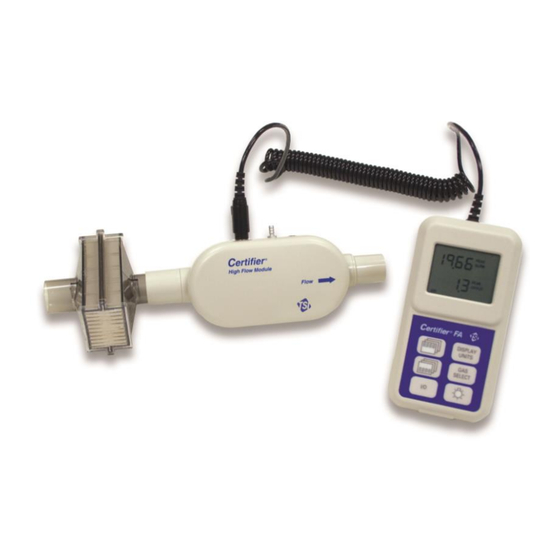
Page 10: Figure 1. The Certifier ® Fa Test System
Controller module Low Flow module Oxygen sensor High Flow module ® Figure 1. The Certifier FA Test System WARNING To avoid the risk of explosion, do not use in the presence of flammable anesthetic gases. Only qualified and trained service technicians are authorized to ®... -
Page 11: Parts List
1.1 Parts List Carefully unpack the test system components from the shipping container. Check the individual parts against the packing list and notify TSI immediately if anything is missing or damaged. Table 1 ® summarizes the Certifier FA Test System components and part numbers shown in Figure 2. -
Page 12: Table 1. Certifier Fa Test System Parts List
® Table 1. Certifier FA Test System Parts List Item Part Description High Flow standard kit (part no. 4070) Controller module 4078 High Flow module 4071 Bacteria filter, 22-mm x 22-mm 1602341 male/female, for use with High Flow module (single use) ®... - Page 13 ® Table 1. Certifier FA Test System Parts List (cont) Item Part Description Low Flow standard kit (part no. 4075) Controller module 4078 Low Flow module 4074 Bacteria filter, barbed fittings, for use with 1040045 Low Flow module (single use) ®...
-
Page 14: Glossary
® Table 1. Certifier FA Test System Parts List (cont) Item Part Description Low Flow module kit (optional) (part no. 4072) Low Flow module 4074 Bacteria filter, barbed fittings, for use with 1040045 Low Flow module (single use) Mounting bracket (includes mounting 1040044 bracket, screws, and Velcro strap) Oxygen sensor kit (optional) (part no. -
Page 15: Setup
2 Setup ® Follow these steps to set up the Certifier FA Test System: CAUTION ® To avoid damage to the Certifier FA Test System components, always use bacteria filters upstream of the flow modules, and always cap flow module ports when not in use. 1. -
Page 16: Figure 4. Connecting The Bacteria Filters To The Flow Modules
2. Attach the bacteria filter to the flow module (Figure 4). Install the bacteria filter to the flow module inlet or upstream of all ® Certifier FA Test System components. Make sure the filter is in the correct orientation by aligning the filter’s flow arrow with the direction of the flow, ensuring that the filter’s inlet indicator (labeled “INLET”, “I”, or other) faces upstream of the flow module, or that the outlet indicator (label “Patent side”, “Outlet”... -
Page 17: Figure 5. Attaching Pressure Tubing To The High Flow Module
3. High Flow module only: install pressure tubing (Figure 5). Attach one end of the pressure tubing to the low-pressure port on the flow module, and the other to the pressure port in the circuit. Pressure tubing High Flow module Figure 5. -
Page 18: Figure 6. Attaching The Oxygen Sensor To The High Flow Module
4. High Flow module only: install the oxygen sensor (optional, Figure 6). Plug the oxygen sensor cable into the High Flow module and oxygen sensor. Turn the cable collar to secure the cable to the oxygen sensor. Use the threaded tee to install the oxygen sensor into the circuit. -
Page 19: Figure 7. Installing A Flow Module Into The Test Circuit
5. Install the flow module into the test circuit (Figure 7, Figure 8). Align the flow direction of the flow module and filter with the direction of flow through the circuit. Ventilator Figure 7. Installing a Flow Module into the Test Circuit 2: Setup... -
Page 20: Figure 8. Certifier Fa Test System Installed In An Oxygen Concentrator Circuit
Oxygen Concentrator ® Figure 8. Certifier FA Test System Installed in an Oxygen Concentrator Circuit 2: Setup... -
Page 21: Operation
3 Operation 3.1 Power Up Pull the protective caps from the flow module ports before powering up. Do not apply pressure to the flow module at power up (this ensures accurate low-pressure transducer zero calibration). Press the I/O (on/off) key on the controller module to power up the ®... -
Page 22: Keypad Functions
3.2 Keypad Functions ® Table 2 summarizes the primary functions of the Certifier FA Test System keypad (Figure 9). DISPLAY Top line UNITS key select key GAS SELECT Bottom line select key Backlight ON/OFF on/off key Figure 9. Controller Module Keypad Table 2. -
Page 23: Measurements
3. Once power up is complete, press the Top line select and Bottom line select keys to select the measurements to be displayed. See Section 3.4, Measurements, for details on each parameter. You can change the display selections and connect or disconnect the flow module or oxygen sensor at any time during normal operation. -
Page 24: Peak Flow Rate
3.4.2 Peak Flow Rate Maximum flow rate during the inhalation cycle of a breath can be displayed on the top line of the control module display. Units of standard liters per minute, indicated by “PEAK SLPM”, and actual liters per minute, indicated by “LPM”, can be selected using the DISPLAY UNITS key. -
Page 25: Stacked Volume
3.4.5 Stacked Volume Total volume over a displayed number of inhalation cycles can be displayed on the top line of the control module display with the number of inhalation cycles displayed on the bottom line of the display. Units of actual liters, indicated by “ATP S L”; standard liters, indicated by “STP S L”;... -
Page 26: Peak Pressure
NOTE: For distinguishing low pressure from absolute pressure, the resolution for low pressure is in 0.1 cmH O or mmHg and absolute pressure measurement (Section 3.4.13) is displayed in resolution of 1 mmHg. 3.4.8 Peak Pressure Peak gauge pressure from the low-pressure port of the High Flow module during the inhalation cycle can be displayed on the bottom line of the control module display. -
Page 27: I Time
NOTE: The inhalation time is defined as the time of positive inhalation flow and does not include the breath hold time. If the vents FA’s ® inhalation time includes the inhalation pause time, the Certifier I:E ratio will not match the vents I:E ratio. 3.4.12 I Time The inhalation time (I TIME) can be displayed on the bottom line of the control module display. -
Page 28: Required Pre-Test Calibrations
3.5 Required Pre-test Calibrations 3.5.1 Low-Pressure Transducer Zero Calibration ® The Certifier FA Test System automatically performs a low-pressure transducer zero calibration at power up. Check the low pressure zero by disconnecting the pressure tubing from the flow module before each low-pressure measurement after initial power up to ensure the most accurate readings. -
Page 29: Breathing Cycles And Trigger Levels
5. If the calibration is successful, CAL disappears and the O concentration is shown on the display. This can take several minutes while the oxygen concentration and sensor stabilize. 6. If the calibration is not successful (oxygen sensor symbol continues to flash, no O concentration is shown), repeat the calibration. -
Page 30: Display Information
Follow these steps to view or adjust the flow trigger level. 1. Momentarily press the Top line select key until volume parameter is on the display, see Section 3.4.3. 2. Press and hold the Top line select key until the “trig” appears on the bottom of the display. - Page 31 Table 3. Screen Displays (cont.) Display Meaning Atmospheric temperature and pressure: a condition ® of volume measurement. The Certifier FA Test System calculates the ATP value by applying the actual gas temperature and pressure to the STP measurement. Breaths per minute: a unit of respiratory rate. Can be displayed on the bottom line (either High Flow or Low Flow module attached).
- Page 32 Table 3. Screen Displays (cont.) Display Meaning 100% oxygen supply gas, selected using the GAS SELECT key (when High Flow or Low Flow module is attached). PEAK Peak flow or pressure. Peak flow can be displayed on top line (when High Flow or Low Flow module is attached).
-
Page 33: Troubleshooting
4 Troubleshooting Table 4 lists the symptoms, possible causes, and recommended corrective actions for problems you may encounter with the ® Certifier FA Test System. If the symptom is not listed, or if none of the recommended corrective actions solves the problem, please contact TSI Customer Support at (800) 874-2811 or 651-490-2811. - Page 34 ® Table 4. Troubleshooting the Certifier FA Test System (cont.) Symptom Possible Cause Corrective Action Can’t select Oxygen sensor not Connect oxygen sensor AIR O mixtures. connected. Look for cable to High Flow oxygen sensor module and oxygen sensor. symbol, Volume, minute Less than two Wait for at least two...
- Page 35 ® Table 4. Troubleshooting the Certifier FA Test System (cont.) Symptom Possible Cause Corrective Action Oxygen sensor 21% oxygen and/or Verify that calibration calibration takes 100% oxygen not gases are 21% oxygen longer than 5 supplied for and 100% oxygen and minutes.
- Page 36 (This page intentionally left blank) 4: Troubleshooting...
-
Page 37: Maintenance
5 Maintenance 5.1 Replacing the Batteries (as required) Replace the batteries when the low battery voltage symbol is displayed or instrument will not power up. 1. Turn off the controller module. 2. Use the pocket driver tool (supplied) to loosen the screw that holds the battery cover on the controller module back panel. -
Page 38: Factory Calibration (Yearly)
2. Package the flow modules carefully to avoid damage during shipping. NOTE: It is not necessary to return the controller module for factory calibration. U.S. & International United Kingdom TSI Incorporated TSI Instruments Ltd. 500 Cardigan Road Tel: (44) 1494 459200 Shoreview MN 55126-3996 Fax: (44) 1494 459700 E-mail: tsiuk@tsi.com... -
Page 39: Specifications
6 Specifications NOTE: Specifications are subject to change without notice. 6.1 Physical Dimensions Controller module: 13.2 cm x 7 cm x 3.3 cm (5.2 in. x 2.8 in. x 1.3 in.). High Flow module: 18 cm x 6.6 cm x 4 cm (7.1 in. x 2.6 in. x 1.6 in.). Low Flow module: 12.7 cm x 5.1 cm x 2.8 cm (5.0 in. - Page 40 Measurement High Flow Module Low Flow Module Pressure drop Maximum between inlet and Maximum between inlet and outlet ports at 101.3 kPa (14.7 outlet ports at 101.3 kPa (14.7 psia) including filter: 0.50 cmH psia) including filter: 4 cmH at 20 SLPM, 1.50 cmH O at 50 at 2 SLPM, 16 cmH O at 5...
-
Page 41: Calibration Requirements
Measurement High Flow Module Low Flow Module Peak & PEEP Low Pressure Range 0 to 150.0 cmH Not applicable. (0 to 110 mmHg) 0.75% of reading or 0.20 Accuracy Not applicable. O (0.15 mmHg), whichever is greater. Barometric Pressure Range 375 to 1500 mmHg. - Page 42 TSI Incorporated – Visit our website www.tsi.com for more information. Tel: +1 800 874 2811 India Tel: +91 80 67877200 Tel: +44 149 4 459200 China Tel: +86 10 8219 7688 France Tel: +33 1 41 19 21 99 Singapore Tel: +65 6595 6388 Germany Tel: +49 241 523030 P/N 1980436 Rev L Copyright ©...
Need help?
Do you have a question about the CERTIFIER FA and is the answer not in the manual?
Questions and answers