
Subscribe to Our Youtube Channel
Related Manuals for Servomex SERVOTOUGH SpectraExact 2500 Series


Summary of Contents for Servomex SERVOTOUGH SpectraExact 2500 Series
- Page 1 SERVOTOUGH SpectraExact (2500 series) Process Gas Analysers Installation Manual Part Number: 02500005D Revision: Language: UK English...
- Page 2 This page intentionally blank...
- Page 3 Servomex 2500 Series Process Gas Analysers Installation Manual Ref:02500/005D/0 Order as part 02500005D...
- Page 5 WARNING, CAUTIONS AND NOTES This publication includes WARNINGS, CAUTIONS and NOTES which provide, where appropriate, information relating to the following: • WARNINGS: Hazards which will result in personal injury or death. • CAUTIONS: Hazards which will result in equipment or property damage. •...
-
Page 7: Table Of Contents
Table of Contents SECTION 1 INTRODUCTION ......... 1.1 Introduction . - Page 8 SECTION 4 INSTALLATION GAS CONNECTIONS ..... . . 4.1 Purge Connections (EU1/EX1) ........4.1 4.1.1 General Purge Connections .
- Page 9 SECTION 8 CE MARKING AND OTHER SAFETY APPROVALS ... . 8.1 EMC and Electrical Safety ........8.1 ATEX Directive and other non-European Hazardous Area approvals .
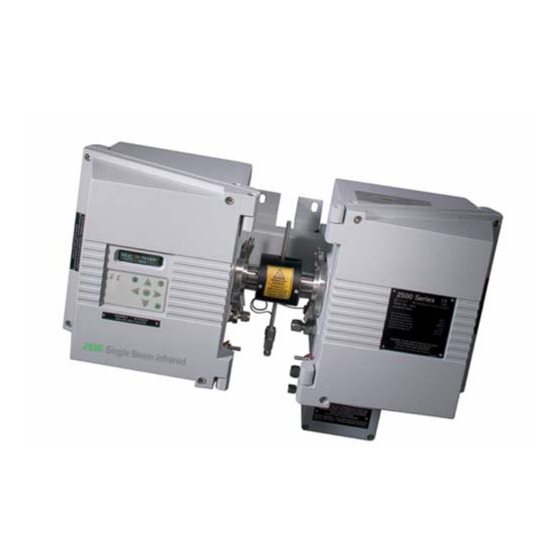
- Page 10 List of Figures Figure 1.1 2500 Overall View ........1.2 Figure 1.2 2500 Construction .
-
Page 11: Introduction
Details of the hardware and instructions for servicing, by qualified personnel only, are presented in the 2500 Service Manual which may be ordered from Servomex. Technical assistance and spare parts are available from Servomex outlets (or their local agents) listed on the back cover. -
Page 12: General Description
General Description The Servomex 2500 Series is a single beam, multi wavelength process analyser suitable for monitoring up to three components in a gas sample stream (2550). It is supplied configured to the customer's precise analytical requirements for a stated analysis in a specific background stream. -
Page 13: Basic Construction
WARNING The EU1 and EX1 versions are intended for use with a suitably certified Purge Control System (PCS). Do not install the EU1 or EX1 version in a hazardous area without a purge controller. The analyser's software is menu driven and has been designed to be as intuitive as possible, enabling the user to fully operate and control the 2500 with the minimum of familiarisation. -
Page 14: Options And Accessories
Figure 1.2 2500 Construction The detector end (left side) contains the detector assembly and also the main electronic circuit boards. The display and control panel is also mounted in the hinged lid of this end. Options and Accessories The 2500 supplied may have been fitted with customer specified options and/or accessories. -
Page 15: Heated Sample Cell - Steam
1.4.2 Heated Sample Cell – Steam Where fitted, this is a steam heating coil which must be supplied with low pressure steam by the user and vented to atmosphere, to maintain a cell temperature of approximately 100°C. This allows cell heating in hazardous areas up to Zone 1/Div. 1 classification, and is normally used with the EU1 and EX1 versions only. -
Page 16: Digital Communications Options
WARNING Standard transducers are not suitable for oxygen service. Sample Temperature Compensation • A type 'K' thermocouple in stainless steel sheath is supplied, and a continuous temperature measurement is made by the 2500 over the range -50 to 200°C (-58 to 392°F). -
Page 17: Installation - General
Lift in the approved manner and remove the 2500 analyser from its packing and inspect for any damage incurred during transit. If any damage has occurred inform Servomex or their agents immediately. Retain packing, in case it is required to return the analyser... -
Page 18: Electrical Connections
After the initial visual inspection, carry out the following checks. Beware gas strut action of the hinged covers. • Check that the serial number of the 2500 (located inside source end and also marked on the external rating label) corresponds to the serial number given in the Manufacturing Data Sheet found at the front of this manual. -
Page 19: Installation
Installation WARNINGS • The 2500 Series analysers are not suitable for use in hazardous areas unless the correct certification labels have been affixed by Servomex and a suitable purge control system is installed (EU1 and EX1 versions). • The installer must be satisfied that the 2500 analyser installation... -
Page 20: Mounting Details
WARNING EU1 and EX1 versions must be used with a Purge Control System, which meets the necessary pressurisation and certification requirements as detailed in the Safety Certificate Manual. If a gas sample conditioning system is to be connected it must be designed to provide a filtered, clean, non-condensing sample for the analyser with no risk of a possible carry- over of condensate into the sample cell. -
Page 21: Figure 2.1 2500 Positioning Restrictions
When mounting the analyser ensure that the panel or brackets employed are adequate to take the weight and there is a minimum clearance above the casing of 500mm (20") to provide space to open the end covers. Fig 2.2 provides mounting details and a table of mounting hole spacings for the various cell lengths. -
Page 22: Figure 2.2 2500 Mounting Details
Figure 2.2 2500 Mounting Details Once mounted, the two yellow lifting handles and their spacers MUST be removed by unscrewing the securing screws. Press the black pop-in plugs supplied into the vacant screw holes and retain the handles for possible future use. -
Page 23: Instructions Specific To Hazardous Area Installations
Instructions Specific to Hazardous Area Installations (Reference European ATEX Directive 94/9/EC, Annex ll, 1.0.6.) The following instructions apply to equipment covered by certificate numbers: Sira 09ATEX1341X, IECEx SIR09.0136X, Sira 10ATEX4015X, Sira 10ATEX 9016X and IECEx SIR 10. 0007X 2.5.1 The equipment may be located where flammable gases and vapours of groups llA, llB and llC may be present. -
Page 24: Atex Label Information
ATEX Label Information 2.6.1 EU1 T5 (Unheated Cell) 2.6.2 EU1 T4 (Steam Heated Cell) - Page 25 2.6.3 EU2 T4 and DU1 T80°C (Unheated Cell) 2.6.4 EU2 T4 and DU1 T125°C (Heated Cell)
- Page 26 2.6.5 EU2 T3 and DU1 T175°C (Heated Cell) 2.10...
-
Page 27: Installation - Electrical
SECTION 3 INSTALLATION – ELECTRICAL WARNINGS • Lethal voltage: mains AC power supplies are potentially lethal. The installer must ensure that the power supply has been isolated before commencing installation. • The installer must be satisfied that the 2500 analyser installation conforms to the relevant safety requirements, national electrical code and any other local regulations, and that the installation is safe for any extremes of conditions which may be experienced in the operating... - Page 28 WARNING (EU1 AND EX1 VERSIONS) AC Power for Zone 1 (EU1 and EX1) versions may only be connected via a suitably certified Purge Control System. Refer to the PCS manual for details. The mains power connection to the instrument is made via the purged electrical filter unit attached to the outside of the case.
-
Page 29: Figure 3.1A 2500 Ac Power And Valve Connections (Purged Filter)
Figure 3.1a 2500 AC Power and Valve Connections (Purged Filter) -
Page 30: Figure 3.1B 2500 Ac Power And Valve Connections (Non-Purged Filter)
Figure 3.1b 2500 AC Power and Valve Connections (Non-Purged Filter) -
Page 31: Figure 3.2 2500 Series Terminal Locations
Figure 3.2 2500 Series Terminal Locations... -
Page 32: Signal Connections
To minimize the effects of interference from RF fields, each mA output cable pair, the RS485 cable (if fitted) and the Ethernet cable (if fitted) shall be looped once through a Steward type 28B0562-200 or equivalent ferrite (Servomex Part No. 2824-0017). Refer to Figure 3.3. -
Page 33: Analogue Outputs
3.2.1 Analogue Outputs Figure 3.4 SIB and Optional Output PCB's Each analogue output is supplied set for current output and may be configured by the user to be 0-20mA or 4-20mA, and be assigned a particular range of operation, in software. -
Page 34: Table 3.1 Analogue Output Connections
WARNING (EU1 and EX1 VERSIONS) Where the 2500 is located in an area that requires EPL Gb, a suitable Relay Box should be used to isolate the outputs. This Relay Box should be switched from the Purge Control System. Each analogue output (and each relay output) has an individual identity in software. This identity is a number, which relates to the "slot"... -
Page 35: Analogue Output Link Selections On Sensor Interface
3.2.2 Analogue Output Link Selections on Sensor Interface Board (SIB) PCB After connecting up the required analogue outputs, the user should make the following hardware link selections on the SIB PCB and (where fitted) Option PCB(s). Refer to Figure 3.3.4 for general schematic of both these types of PCB. Carefully remove the PCB for link selection and be sure to replace it in the correct slot and in the correct orientation. -
Page 36: Relay Outputs
3.2.3 Relay Outputs NOTE Each relay output is supplied set for NC (i.e. Normally Closed under "Safe" condition) operation, and may be assigned to a particular alarm or signalling function in software. This is described in the Quickstart manual. User selection of NC or NO operation is described in Section 3.2.4. As with the analogue outputs, each relay has its own software identity relating to the slot in which the PCB, on which it is physically located, resides. -
Page 37: Control Connections
WARNING Setting the relays to Normally Open (N.O.) operation will mean that there is no fail-safe action since any loss of cable continuity will prevent an alarm being signalled. NOTE Regardless of N.O./ N.C. setting, the relays will always be in "alarm" state wherever there is no power applied to the 2500, or when they are unassigned. -
Page 38: Range Change Input
3.3.1 Range Change Input Every analogue output can be independently scaled in software to represent some or all of the calibrated range of the instrument, as described in the Quickstart manual. However, under some process conditions (e.g. plant start-up) it may be desirable to have different output ranges on demand. -
Page 39: Sample Flow Sensor Input
WARNING If the Keyswitch is left "ON" (contacts closed), access is continuously available to all normally protected areas of the software. 3.3.4 Sample Flow Sensor Input If the sampling system supplying the process sample to the 2500 is fitted with a loss of flow sensor, this can be connected to the 2500 to enable the "loss of sample flow"... -
Page 40: Externally Powered Solenoid Valve Connections
WARNING If installation is in a hazardous area, use suitable certified solenoid valves. NOTE Valve (SV3) reverts to OFF in Shutdown (Serious Fault) condition. The use of the optional 3rd "Sample/Inert valve will prevent sample entering the 2500 sample cell while the cell or chopper box under temperature diagnostic is activated, i.e. -
Page 41: Internally Powered Solenoid Valve Connections
3.3.7 Internally Powered Solenoid Valve Connections Connect to solenoid valve relays SV1, SV2 and SV3 as detailed below. Take care to ensure that internal 12VA (total) rating of the 24VDC supply is not exceeded. Table 3.5 – Internally Powered Solenoid Valve Connections Valve State (ON=Current Flow Through Solenoid) Span/Zero... -
Page 42: Digital Connections
Figure 3.5 Auto calibration Valve Configuration Digital Connections NOTE All digital cables must have a braided overall screen or armour. The screen must be terminated at the point of entry to the case. This will be by using a gland, which makes a connection between the cable screen and the case. -
Page 43: Table 3.6 Serial Data Format
Table 3.6 – Serial Data Format Item Size Description <CR> 1 byte Carriage return character (ASCII code 13). date; 8 bytes dd/mm/yy or mm/dd/yy depending on user settings. time; 8 bytes hh:mm:ss number of 1 byte 1 byte Number of components fitted components (range 1-3) <CR><LF>... - Page 44 Table 3.6 – Serial Data Format component 2 Max5 bytes Concentration for component 2 as defined concentration; for measure display. (if fitted) component 2 units; Max 3 bytes Units defined for component 2. (if fitted) component 2 alarm 4 bytes One byte for each alarm.
- Page 45 Table 3.6 – Serial Data Format component 3 Auto 1 byte or Indicates Auto calibration phase. calibration status; 15 bytes 0 = Not in Auto calibration 1 = In span preflush 2 = In zero cal 3 = zero corrected. This is then followed by two additional values, which are separated by commas, each 6 bytes that represent the zero before calibration and the zero after...
- Page 46 Table 3.6 – Serial Data Format checksum; 4 bytes ASCII representation of 16 bit checksum (modulo 65536), calculated by adding all data preceding the checksum together. <CR><LF> 2 bytes Carriage return and Line Feed characters (ASCII codes 13 and 10 respectively). <CR><LF>...
-
Page 47: Table 3.7 Fault Number Reference
Table 3.7 – Fault Number Reference Fault Number Display Message OPTICAL BENCH POWER FAILURE SOURCE VOLTAGE HIGH SOURCE VOLTAGE LOW INFRARED SOURCE FAILURE CHOPPER MOTOR OUT OF LOCK SAMPLE FLOW FAILURE CHOPPER TEMP HIGH CHOPPER TEMP LOW CHOPPER TEMP SENSOR FAILURE CELL TEMP HIGH CELL TEMP LOW CELL TEMP SENSOR FAILURE... -
Page 48: Table 3.8 Ascii Characters
Some characters defined by the 2500 are non-standard characters, i.e. not part of the ASCII character set. These either occupy the ASCII codes above 127 or redefine an ASCII code as another character. When these characters are used, for example in the component formula, they will be substituted with a valid ASCII character prior to output on the RS232. -
Page 49: Modbus Rs-485 Connection
WARNING Do not use an uncertified dcs, datalogger or printer in a hazardous area. 3.4.2 Modbus RS-485 Connection Modbus communications over an RS-485 interface requires the Communications Board RS-485 option PCB 02500912. This is fitted vertically above the Power Control PCB in the source end assembly. -
Page 50: Pressure Transducer Connections - (If Supplied)
For guidance, the tables below show the corresponding wire colours specified in TIA/ EIA-568A and TIA/IEA-568B for patch leads as viewed from the back of the plug with the tab facing down. It is the responsibility of the installer to ensure the correct connections are made. -
Page 51: Figure 3.6 Typical Pressure Transducer Assembly
Figure 3.6 Typical Pressure Transducer Assembly 3.25... - Page 52 3.26...
-
Page 53: Installation Gas Connections
SECTION 4 INSTALLATION GAS CONNECTIONS Purge Connections (EU1/EX1) The next phase of the installation is to connect up any safety purge system required for safe operation in a hazardous area. 4.1.1 General Purge Connections WARNING (EU1 AND EX1 VERSIONS) Where appropriate, the user must refer to the detailed instructions provided in the manual supplied with the Purge Control System, and use them in conjunction with the following instructions. - Page 54 The general schematic for a hazardous area purge system is shown in Figure 4.1. WARNINGS (FIGURE 4.1) If this component is mounted in a hazardous area it should be protected by one of the types of protection listed in EN/IEC 60079-0. All cable glands for use in electrical cable entries shall be of a type which seals and clamps the cable.
-
Page 55: End Boss Purge Connection
NOTES (FIGURE 4.1) The PCS shall incorporate a purge timer that shall be set to not less than the minimum specified (11 minutes). The purge timer shall be re-set to zero if either the minimum overpressure or minimum purge flow is not maintained. The PCS shall incorporate a device to ensure that power is not connected to the apparatus being protected until the specified purge time has elapsed. -
Page 56: End Boss Vents
4.2.3 End Boss Vents When a flammable, severely corrosive or toxic gas or liquid is present in the sample cell, either as the sample or a background gas, additional issues arise. The construction of the cell window seal is such that any leak of the seal or failure of the window will result in the sample gas entering the end boss, but not being released to the surrounding atmosphere or directly into the analyser enclosure. -
Page 57: Figure 4.2 Cell End Boss Connection
NOTE Vent lines, if required, should be connected to end boss bottom tappings. Purge gas should be connected to top tappings when required. When not required, top tappings should be plugged. IF FITTED, COMMENCE END BOSS PURGE FROM THIS POINT ONWARDS. WARNING Where the sample is corrosive or toxic, the vent lines from the end bosses must take away any potential leakage to a safe disposal point. -
Page 58: Steam Heated Cell
Steam Heated Cell Some 2500's are fitted with steam heated cells, and at this stage suitable low pressure steam, typically at 14-21kPa, 2-3 psig venting to atmosphere after the cell, should be connected ready for use, but do not pass steam into the heating coil yet. Fittings for 1/8"... - Page 59 The normal measurement display will then appear and the 2500 will be operational. NOTES • The measurement will not be valid at this point since process sample is not yet flowing. • If a heated cell is fitted, it will not yet be up to temperature and the intermittent "warming up"...
-
Page 61: Fault Diagnosis And Cell Maintenance
SECTION 5 FAULT DIAGNOSIS AND CELL MAINTENANCE Introduction A fault will be signalled wherever any parameter measured by the 2500's diagnostics becomes out of tolerance. Any Fault condition will be indicated by the Fault LED on the control panel being illuminated. The Fault signal can be assigned to a Relay, as described in the Quickstart Manual. -
Page 62: Table 5.1 Diagnostic Displays (2500, 2520, 2550)
Table 5.1 – Diagnostic Displays (2500, 2520, 2550) Display Description CHOPPER TEMP °C Chopper box temperature COMPENSATION °C Detector temperature CELL TEMP °C Cell temperature (if enabled) SAMPLE TEMP °C Sample Temperature * [Measurement 1] ABS au Absolute absorbance units (M1) [Measurement 2] ABS au Absolute absorbance units (M2) * [Measurement 3] ABS au... -
Page 63: Table 5.2 Diagnostic Displays (2510)
Table 5.2 – Diagnostic Displays (2510) Display Description Chopper box temperature CHOPPER TEMP °C COMPENSATION TEMP °C Detector temperature CELL TEMP °C Cell temperature (if enabled) SAMPLE TEMP °C Sample temperature (if enabled) SAMPLE PRESSURE (units) Sample pressure (if fitted) SOURCE VOLTS Source voltage ABSORBANCE au... -
Page 64: General Fault Conditions
General Fault Conditions When the Fault LED is illuminated, the DISPLAY FAULTS function should be used to determine the nature of the fault. The diagnostics (Section 5.2) may assist in defining the cause, together with the comments given in Table 5.3. Action to cure the fault should be taken as soon as possible. - Page 65 Table 5.3 – General Fault Messages SPAN OUT OF SPAN OUT TOL Failed Autocalibration – bad span TOLERANCE sample – use One Cycle or Manual Span AUTOCAL BAD BAD PREFLUSH Failed Autocalibration – bad PREFLUSH preflush – use One Cycle PASSWORD BAD PASSWORD 3 consecutive Password failures...
-
Page 66: Serious Fault (Shutdown) Conditions
Serious Fault (Shutdown) Conditions If the Fault LED is illuminated and the Analogue Outputs have been driven HIGH (or LOW, depending on selection), a Serious Fault exists and the Measurement Display will show "Measurement Invalid". Immediate action should be taken to rectify the fault, and qualified service personnel should be called. -
Page 67: Figure 5.1 General Cell Construction
Figure 5.1 General Cell Construction CAUTION Use only Servomex supplied spare parts. The use of inferior replacement components may degrade the performance and safety of the instrument. -
Page 68: Figure 5.2 Suppressor Mounting Details
WARNING • Lethal voltages: mains AC power supplies are potentially lethal. The maintainer must ensure that all mains power supplies are disconnected from the supply before maintenance work is started. • Purge the measuring cell and associated pipework with an inert gas before work is started. - Page 69 EXTREMELY EXPENSIVE. The windows may have special anti-reflective coatings and they may easily be damaged by brittle fracture. The standard material chosen by Servomex is Calcium Fluoride. This material is non-toxic and reasonably robust. However, some applications may require materials such as Barium Fluoride, Zinc Selenide, etc.
- Page 70 To remove the window, seal the outlet and with the cell in a vertical position, connect a hand operated aspirator (Servomex p/n 2387-0514) to the inlet. Apply a gentle pressure to lift the window up squarely and remove it.
-
Page 71: Routine Leak Checks
are being used, this will require significant torque, with longer pauses. DO NOT use the cell inlet/outlet stubs as levers. After re-assembly, perform a leak check on the cell using a manometer before installing it in the 2500. Do not submerge the cell or fill it with water. Re-installation of the complete cell assembly onto the 2500 is the reverse of the dismantling process with the added requirement that, unless fitted with a purge, the end bosses should be briefly flushed with clean dry nitrogen after the cell has been... - Page 72 5.12...
-
Page 73: Spares Lists
SECTION 6 SPARES LISTS Spares List The following spares list applies to all versions of the 2500 covered by this manual. The 2500's Model and Serial Number MUST be advised when ordering spares. NOTE For certified versions EU1, EU2, DU1, EX1, EX2 and DX1, only the boards listed may be used as spares 6.1.1 General... -
Page 74: Sample Cell Spares
Table 6.1 – General Spares List Transformer, 100/200 volts 00608334 Special Tools Kit S2500979 Enclosure Earth Studs S2500984 Pressure Transducer S2500987 Chopper Motor S2500986 Chopper Box Seals Kit S2500988 Gas Strut Kit S2500989 Fuse Kit 02501996 Multi component Adaptor PCB (2550 only) S2550901 10 x Gas Filter Correlation Adaptor PCB (2510 only) S2510901A... -
Page 75: Source Units
6.1.3 Source Units (Refer to Final Specification Sheet) Table 6.3 – Source Unit Spares Description Part Number Long Wave, CaF S2500931C Long Wave, BaF S2500931B Long Wave, ZnSe S2500931A Short Wave, CaF S2500943A Short Wave, Glass S2500943B Soft UV CaF (2520 Only) S2520933A 6.1.4... -
Page 76: Windows
6.1.5 Windows (Refer to Final Specification Sheet) Table 6.5 – Window Spares Description Part Number S2500980A S2500980B ZnSe S2500980C Quartz S2500980D Glass S2500980E Sapphire S2500980G 6.1.6 Scrubbers (Refer to Final Specification Sheet) Table 6.6 – Scrubber Spares Detector / Cell Boss Scrubber (H O) Marked 'W' S1200921 Detector / Cell Boss Scrubber (H... -
Page 77: Recommended Spares
Recommended Spares Quantity for 2 years. Table 6.7 – Recommended Spares Item Part Number 1-3 Analysers 4-9 Analysers Fuse Kit 02501996 Cell Servicing Kit S2500981 PTFE Tape 1835-3026 Chopper Motor S2500986 Cell sealing Kit Refer to application Hand Aspirator 2387-0514 Windows Refer to application Chopper Box Scrubber... -
Page 79: Instrument Specifications
SECTION 7 INSTRUMENT SPECIFICATIONS Generic 2500 Series Performance 7.1.1 Environmental Specifications Table 7.1 – General Environmental Specifications Operating Temperature GEN, EU1, EU2, DU1, EX1, EX2, DX1, HTV 0-55°C (32-131°F) Operating Humidity 0-95% RH, non-condensing Storage Temperature -25°C(-13°F) to +70°C (158°F) Storage Humidity 0-95% RH, non-condensing Altitude... -
Page 80: Performance Characteristics (Each Component)
Fitted with an unscreened power cable. Also included were two separate mA output cables, each individually screened. Each signal pair was fitted with ferrite bead (Servomex part No. 2824-0017). The screens and drain wires were terminated at the glands. Results: Met the requirements of EN 61326, Table 4, Class B (Equipment for use in domestic establishments) in respect of conducted and radiated emissions. -
Page 81: Sample Specification
Table 7.3 – Sampling Specification Sample Temperature 0-180°C/32-356°F (see sampling influences) Sample Pressure 0-150 psig/0-10 barg (normal) (For special high pressure operation consult Servomex) Sample Flow (typical) GAS 0.2-5.0 litres/min LIQUIDS 0.3-1.0 litres/min (Constant flow rate preferred) Sample Wetted Materials Refer to Final Specification Sheet 7.1.7... -
Page 82: Analogue Outputs
7.1.9 Analogue Outputs 2 x mA outputs, plus 3 x relay outputs. Optionally additional 2 x mA, plus 2 x relay outputs. All analogue mA outputs are assignable and selected as 0-20mA or 4-20mA (max. impedance 1KOhm) or alternatively 0-10V or 2-10V (min. impedance 1MOhm). Dual ranges on every Analogue output. -
Page 83: Ethernet
7.1.12 Ethernet Communication over Ethernet using option board. This provides a 10/100M Ethernet interface and uses the Modbus TCP protocol. User interface allows the IP address, subnet mask and gateway address to be entered. All fields default to zeros. A provisional subnet mask is generated whenever an IP address is entered that falls into a different class. -
Page 85: Ce Marking And Other Safety Approvals
SECTION 8 CE MARKING AND OTHER SAFETY APPROVALS EMC and Electrical Safety • The Analyser complies with the European Community “Electromagnetic Compatibility Directive”: • Emissions: Equipment suitable for use in domestic establishments and in establishments directly connected to a low voltage supply which supplies buildings for domestic purposes. -
Page 86: Atex Directive And Other Non-European Hazardous Area Approvals
ATEX Directive and other non-European Hazardous Area approvals ATEX Directive 94/9/EEC NOTE Depending on the variant ordered an additional Safety Certificate Manual may be supplied. This contains all the relevant safety certificates and declarations for the EU1, EU2, EX1 and EX2 variants. WARNING The installer and/or the user of the analyser must be satisfied that the installation complies with any "Special Conditions for Safe Use"... - Page 87 Table 8.1 – 02500 Safety Approvals The 02500 Series EX1 version is IECEx certified to Type ‘p’ standard IEC60079-2 and is suitable for use in areas that require EPL Gb. The analyser is marked Ex px ia [ia] IIC T5 Gb. The 02500 Series EX2 version is IECEx certified to Type ‘n’...
-
Page 89: Appendix A Modbus Data Mapping
APPENDIX A- Modbus Data Mapping When fitted with one of the optional communication boards, the 2500 series analysers are capable of bi-directional digital communications based on the Modbus protocol. The following facilities are provided:- • Access to measurements • Access to measurement diagnostic values •... -
Page 90: Measurement Summary
Measurement Summary This block of registers allows all primary measurement components to be read in single query. This register data is read-only and may be accessed with function codes 03 and 04. Register Register Name Data Comments Number Address Type Number of integer Number of fitted measurement... -
Page 91: Measurement Diagnostics
Measurement Diagnostics This register data is read-only and may be accessed with function code 03 and 04. Register Register Name Data Comments Number Address Type 201-202 200-201 Sample pressure float Sample pressure (zero if not fitted) 203-204 202-203 Chopper temperature float Chopper temperature as 205-206... -
Page 92: Fault Data
* Note that measurements 2 and 3 are optional and may only be present in 2550 instruments. Where not fitted these values will be zero. Fault Data This coil / discrete input data is read-only and may be accessed with function code 01 and 02. -
Page 93: Autocalibration Setup
Password violation System clock inoperative System ADC inoperative Default system data corruption Bit = 1 indicates specified fault condition Calibration data corruption present Utility data corruption Alarm / relay data corruption Analogue assignment data corruption Bad span ignored Autocalibration Setup These registers allow the autocalibration settings to be read using function codes 03 and 04 and to be written using function codes 06 and 16 (see note 1). -
Page 94: Autocalibration Control
Notes:- Any attemp to write a register in the above range, whilst an autocalibration is in progress, will return an exception response 06 (slave busy). Register values will not be updated. Measurements 2 & 3 are optional and may only be present in 2550 instruments. Where not fitted reading these values will return zero. -
Page 95: Autocalibration Status
Autocalibration Status This register data is read-only and may be accessed with function code 03 and 04. Register Register Name Data Comments Number Address Type Autocalibration Phase Integer Value indicates autocalibration phase as follows:- 0 = Not in autocalibration 1 = In span pre flush 2 = In zero calibration 3 = Zero corrected 4 = In span calibration... - Page 96 422-423 421-422 Measurement 3 zero pre- float calibration * These values are updated during phase 424-425 423-424 Measurement 3 zero post- float 3 of the autocalibration sequence. calibration * 426-427 425-426 Measurement 3 Span pre- float calibration * These values are updated during phase 5 of the autocalibration sequence.
-
Page 97: Appendix B Equipment Protection Levels
APPENDIX B - Equipment Protection Levels. Traditional Relationship of Equipment Protection Levels (EPLs) to Zones Equipment Protection Level (EPL) Zone For more information on Equipment Protection Levels (EPLs) refer to Annex D of IEC 60079-0:2007 or EN60079-0:2009. - Page 99 Crowbrough East Sussex TN63FB England Tel: (44) 1892 652181 Fax: (44) 1892 662253 Global email: info@servomex.com If you send the analyser to Servomex or your local Servomex analyser for disposal, it must be accompanied by a correctly completed decontamination certificate.
Need help?
Do you have a question about the SERVOTOUGH SpectraExact 2500 Series and is the answer not in the manual?
Questions and answers