
Related Manuals for Servomex SERVOPRO Plasma


Summary of Contents for Servomex SERVOPRO Plasma
- Page 1 SERVOPRO Plasma OPERATOR MANUAL Part Number: 02001001A Revision: Language: UK English...
- Page 2 This page intentionally blank...
-
Page 3: Table Of Contents
Plasma Gas Analyzer CONTENTS Section Page DESCRIPTION AND DEFINITIONS ............... 5 Scope of this manual ..................5 Safety information ................... 5 Description ...................... 6 1.3.1 Ordering options ..................6 1.3.2 02001 Analyzer layout ................7 SPECIFICATION .................... 9 General ......................9 Environmental limits .................. - Page 4 Plasma Gas Analyzer 5.8.7 Averaging Number ................... 49 5.8.8 Calibration done parameters ..............50 ROUTINE MAINTENANCE (STANDARD ANALYZER) ....... 51 Cleaning the analyzer ................... 51 Inspecting/replacing the fuse (when necessary) .......... 52 SPARES ....................... 53 STORAGE AND DISPOSAL ................ 53 Storage ......................
- Page 5 Plasma Gas Analyzer Figure 1 - FRONT OF THE ANALYZER................. 7 Figure 2 - REAR OF THE ANALYZER ................... 7 Figure 3 - INTERNAL SCHEMATIC ..................8 Figure 4 - DIMENSIONAL OUTLINE DRAWING ..............14 Figure 5 - INSTALL THE 02001 ANALYZER IN A PANEL ..........15 Figure 6 - REAR VIEW CUT OUT DIMENSIONS ...............
- Page 6 Figure 47 - AUTOMATIC CALIBRATION TIMERS .............. 62 Figure 48 - ANALOG OUTPUT HOLD TO TRACK TRANSFER DELAY ......62 Figure 49 - SERVOPRO PLASMA WITH AUTOMATIC CALIBRATION ......64 Figure 50 - OPERATING PARAMETERS MENU ..............70 Figure 51 - BACKGROUND GAS SELECTION MENU ............71 Figure 52 - TEMPERATURE COEFFICIENT MENU ............
-
Page 7: Description And Definitions
Plasma Gas Analyzer 1 DESCRIPTION AND DEFINITIONS Scope of this manual This manual provides installation, operation and routine maintenance instructions for the SERVOPRO Plasma Trace N Analyzer, abbreviated to "analyzer" in the remainder of this manual. Safety information Read this manual and ensure that you fully understand its content before you attempt to install, use or maintain the analyzer. -
Page 8: Description
SERVOPRO PLASMA Trace N Analyzer can support one gas measurement using a plasma transducer measuring trace level nitrogen in argon or helium. 1.3.1 Ordering options For the latest ordering options please contact your local Servomex agent or visit www.servomex.com 02001001A_9... -
Page 9: 02001 Analyzer Layout
Plasma Gas Analyzer 1.3.2 02001 Analyzer layout Description Keypad LCD display Power inlet Gas connections (Service port) RS-232 port IO Connector Figure 1 - FRONT OF THE ANALYZER Figure 2 - REAR OF THE ANALYZER 02001001A_9... - Page 10 Plasma Gas Analyzer Figure 3 - INTERNAL SCHEMATIC 02001001A_9...
-
Page 11: Specification
Plasma Gas Analyzer 2 SPECIFICATION WARNING The protection, accuracy, operation and condition of the equipment may be impaired if the analyzer is not installed in accordance with the requirements of this and subsequent sections of the manual. WARNING Not suitable for flammable samples. Never pressurise the analyzer. -
Page 12: Electrical Data
Plasma Gas Analyzer Electrical data Electrical supply Voltage: 100 - 120 Vac / 230 - 240 Vac, 50 to 60 Hz (± 10% maximum fluctuation) Two fuses 1 amp / 250 V, Type “F”, Fuse rating / type: Breaking capacity 1.5kA @ 250 V AC miniature fuses 5 x 20 mm Maximum power consumption: Interface signal relay ratings:... -
Page 13: Calibration Gas
Plasma Gas Analyzer Calibration gas The calibration gases must be clean, non-corrosive, free from oil and condensates and compatible with the materials listed in Appendix 1 High calibration set point At least 90% FSD N in Ar or He Low calibration set point 6N Grade Ar or He Performance... -
Page 14: Unpack The Analyzer
It is advisable that the protective caps are kept on prior to fitting. Inspect the analyzer and the other items supplied, and check that they are not damaged. If any item is damaged, immediately contact Servomex or your local Servomex agent. -
Page 15: Installation And Set-Up
Plasma Gas Analyzer 4 INSTALLATION AND SET-UP WARNING The analyzer must be installed by a suitably skilled and competent person. The following procedure must be followed to prevent a hazard. WARNING The analyzer is only suitable for installation in unclassified areas. CAUTION Do not install the analyzer in a frame/rack or on a bench which is subject to high levels of vibration or sudden jolts. - Page 16 Plasma Gas Analyzer Figure 4 - DIMENSIONAL OUTLINE DRAWING 02001001A_9...
-
Page 17: Mechanical Installation Rack Mounting
Plasma Gas Analyzer Mechanical installation rack mounting CAUTION The analyzer must not be supported by the front panel alone. You must provide an additional support under the base of the analyzer towards the rear of the enclosure as shown in Figure 5 - INSTALL THE 02001 ANALYZER IN A PANEL. If you do not, the analyzer may be damaged, or may fall and damage other equipment. -
Page 18: Electrical Installation
Plasma Gas Analyzer Electrical Installation 4.2.1 Electrical Safety WARNING Ensure that the electrical installation of the analyzer conforms with all applicable local and national electrical safety requirements. WARNING Obey the safety instructions given below when you install the analyzer; if you do not, the analyzer warranty may be invalidated, the analyzer may not operate correctly, or it may be damaged. -
Page 19: Connect The Electrical Supply
Plasma Gas Analyzer 4.2.2 Connect the electrical supply WARNING Only use the power supply cord provided with the unit. CAUTION Ensure that the analyzer is suitable for use with your electrical supply voltage and frequency. If the analyzer is not suitable, the analyzer may not operate correctly, or it may be damaged when you operate it. -
Page 20: Milliamp Output Connections
Plasma Gas Analyzer 4.2.3 Milliamp output connections WARNING The milliamp outputs are separated from the analyzer mains circuits by reinforced insulation. The terminals must only be connected to circuits that are themselves separated from mains voltages by an isolation method that provides at least this level of protection. CAUTION To comply with EMC requirements, screened cables must be used to connect the analogue outputs and the screen of the mA output shall be connected to... -
Page 21: Alarm, Remote Range And Status Relay Connections (General)
Plasma Gas Analyzer 4.2.4 Alarm, remote range and status relay connections (general) WARNING The alarm remote range and status relay connections are separated from the analyzer mains circuit by reinforced insulation. The terminals must only be connected to circuits that are themselves separated from mains voltage by an isolation method that provides at least this level of protection. -
Page 22: Alarm Output Option
Plasma Gas Analyzer 4.2.5 Alarm output option With this option, two digital dry contact outputs are available for process alarms. These contacts are always closed for fail safe purposes. They are connected to a terminal strip labelled "AL1" for alarm #1 and "AL2" for alarm #2. One side of each relay is connected to the "C"... - Page 23 Plasma Gas Analyzer displayed under ACTUAL. To exit the alarm #1 input function, press F4. This will bring up the original page 2 of CONFIGURATION MENU To enter the set point for alarm #2, follow the same procedure as above, but press F3, this will bring up the following display.
-
Page 24: Rs232 Connection (Option)
Plasma Gas Analyzer 4.2.6 RS232 connection (option) WARNING The RS232 communications terminals are separated from the analyzer main circuit by reinforced insulation. The terminals must only be connected to circuits that are themselves separated from mains voltages by an isolation method that provides at least this level of protection. - Page 25 Plasma Gas Analyzer The communication parameters of the analyzer are: Baud rate: 9600 Parity bits: none Data bits: Stop bits: The serial port on the rear of the analyzer (Figure 2 item 6) is an RS232 ± 5.5 V 9-way 'D' type connector.
- Page 26 Plasma Gas Analyzer bit 7: alarm 2 1 if alarm 2 is ON bit 6: alarm 1 1 if alarm 1 is ON bit 5: low flow 1 if there is a low flow error bit 4: plasma status 1 if there is a plasma off error bit 3: system status 1 if there is a low flow, plasma off, underscale or overscale error...
-
Page 27: Connect The Sample/ Auto Calibration (Optional) Gas Pipeline(S)
Plasma Gas Analyzer Connect the sample/ auto calibration (optional) gas pipeline(s) WARNING Sample and calibration gases may be toxic or asphyxiant: Ensure that the external connections are leak free at full operating pressure before you use sample or calibration gases. - Page 28 Plasma Gas Analyzer Figure 12 - IDEAL INSTALLATION EXAMPLE PR1 is a miniature stainless steel high purity pressure regulator. The internal volume must be at it’s absolutely minimum. Any unswept dead volume will cause noise and instability and, will cause poor recovery time. PR1 should be installed close to the sample point. PR1 should be installed only if there is large pressure excursion (over 69 kPa (10 PSIG)).
- Page 29 Plasma Gas Analyzer Figure 14 - POOR INSTALLATION EXAMPLE 2 Some users wish to monitor the inlet flow with a falling ball rotameter. Those rotameters (or flowmeters) are calibrated at atmospheric pressure. The flow indicated will be wrong, it must be compensated for the line pressure.
-
Page 30: General Operation
Plasma Gas Analyzer 5 GENERAL OPERATION Power on and start up CAUTION Sample and calibration gases must be as specified in Sections 2.4 and 2.5 . If the pressure/flow rates are outside the ranges specified in Section 2.1, you must regulate the gases externally, before they enter the analyzer. Before putting the power on, be sure that your gas lines are properly purged with good quality argon. -
Page 31: Routine And Operational Verification
Plasma Gas Analyzer On power up the flow control valve (ref. figure 3) is cold and it may take up to two minutes for the gas to flow through. Once the valve is warm the flow will stabilize. If the flow is set to 0 cc for a while the valve will cool down again and require further time to stabilize when flow is re-initiated. -
Page 32: Configuration
Plasma Gas Analyzer Configuration Pressing F1 from the MAIN MENU will bring you to the CONFIGURATION MENU. The CONFIGURATION MENU prompts you to enter three different parameters: 5.3.1 Auto ranging "Auto ranging". Choosing “F1” "yes" allows the analyzer to "switch" automatically between the three possible ranges. -
Page 33: Ma Failure Mode
Plasma Gas Analyzer <<CONFIGURATION MENU>> Page 2 F1:mA failure mode (high/low/off):HIGH No other options available F4:RET Figure 18 - CONFIGURATION MENU - PAGE 2 5.3.4 mA failure mode mA failure mode “F1” : in the case of an “underscale”, "over scale", “low flow” or "plasma off", this option will set the 4-20 mA output : “off “(always remain between 0 and 20 mA, even if an error occurs), “low”... -
Page 34: Calibration
Plasma Gas Analyzer Calibration The calibration menu is shown in Figure 19 In this section, you have to enter the value in ppm of your zero calibration gas and your span calibration gas. The recommended values are between 0 and 20% of the full scale for the zero value, and between 80 and 95% of the full scale for the span value. - Page 35 Plasma Gas Analyzer <<CALIBRATION MENU>> Input SPAN value:0.0 Actual value:0.0 Value must be in PPM F4:RET Figure 21- DISPLAYED WHEN ENTERING SPAN VALUE The analyzer will automatically select the appropriate range based on the span value entered. When you have entered a value and pressed the "E" key (E for enter), the processor checks the format, evaluates it and validates it.
- Page 36 Plasma Gas Analyzer The display shows the actual ppm of nitrogen value and the actual flow in cc. If the unit is started up for the first time or you replace the calibration gas with a new value, the ppm display has no meaning.
-
Page 37: Diagnosis
Plasma Gas Analyzer Diagnosis Pressing "F3" from the MAIN MENU will bring you to the DIAGNOSTIC MENU. The diagnostic feature of the analyzer gives you the opportunity to verify the output of the analogue to digital converter count value and check the 4 - 20 mA output. If you have any options other than standard, you may also verify them (digital and/or fully automatic calibration option). - Page 38 Plasma Gas Analyzer <<DIAGNOSTIC MENU>> Input value (0-100%): F4:RET Figure 25 - DIAGNOSTIC MENU You need only enter any integer number value between 0 and 100 % and press the "E" key for enter. Zero (0) is for 4 mA and one hundred (100) for 20 mA. This makes it easier to calibrate remote monitoring system and also makes it faster to verify the hardware part for the 4 - 20 mA signal isolation module.
-
Page 39: Error And Alarm Historic
Plasma Gas Analyzer 5.5.1 Error and Alarm Historic This menu is very useful. You can see the last 25 alarms with the time and the date. Pressing “F1” from the DIAGNOSTIC MAIN MENU brings you the newest errors and “F2” the oldest. For example, if a low flow error occurs at 9:34:37, the error and alarm historic menu will display the “LOW FLOW”... -
Page 40: Serial Number
Plasma Gas Analyzer 5.5.2 Serial number <<SERIAL NUMBER>> Serial Number:0 F4:RET Figure 27 - SERIAL NUMBER MENU It displays the analyzer serial number, which corresponds to the one written at the back of the analyzer. This can be useful if the back of the analyzer is not accessible. 02001001A_9... -
Page 41: Run
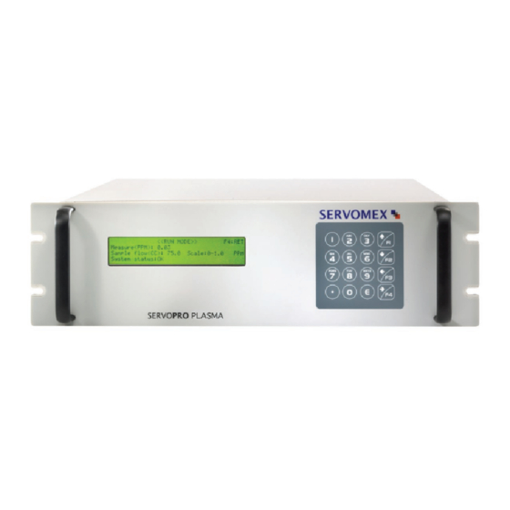
Plasma Gas Analyzer Most of the time, you will be in this mode, which displayed the following screen that is accessible by pressing “F4” from the MAIN MENU. <<RUN MODE>> F4:RET Measure(PPM): 10.0 Sample flow(CC): 75.0 Scale: 0-10 PPM System status:OK Figure 28 - RUN MODE In this mode, the following information is displayed: measurement in ppm, flow in cc, system status, and range in use. -
Page 42: Special Consideration About The 0 - 1 Ppm Range
Plasma Gas Analyzer Other messages can be displayed where the ppm value is normally displayed. You may get "Under scale" if the cell count or the calculated ppm value is too low for that scale. "Over scale" will be displayed if the cell count or calculated ppm value is too high for the scale in use. -
Page 43: Hidden Menu
Plasma Gas Analyzer Hidden Menu By pressing “1”, “2”, “3” and “E” from the Main Menu, the HIDDEN MENU opens. 5.8.1 Starting Count The starting count value is the threshold value where the analyzer switches from starting mode to normal mode. If the cell counts (value from the analogue to digital converter;... -
Page 44: Temperature Coefficient
Most of the time these factors will be set to 1.000 and should not be changed. If you suspect there is an error call Servomex to get the exact procedure to perform the temperature tests. - Page 45 Plasma Gas Analyzer <<<TEMPERATURE GAIN>>> Gain :1.000 Actual:1.000 F4:RET Figure 31 - TEMPERATURE GAIN Minimum: 0 Maximum: 2 Resolution: 0.001 If you have to change the gain compensation factor, enter the value with the numeric keypad and then, press “E” to validate the new value. The menu to enter the compensation factor for the offset looks the same as the one for gain.
-
Page 46: Time And Date Setting
Plasma Gas Analyzer 5.8.3 Time and date setting When you enter in the time and date setting menu, the following menu appears. Enter time first, using the numbers on the keypad. For example, if you wish to enter 15:45:02, you only have to do the following steps. - Page 47 Plasma Gas Analyzer When you enter the time, you are obliged to enter the date. You only have to enter the year, <<<TIME AND DATE SETTING>>> Time 15:46:23 Actual: 00:00:00 Date 05/06/27 Actual: 00/00/00 F3:NEXT F4:RET month and day like you did in the preceding steps for the time. Figure 34 - TIME AND DATE SETTING (3) When you enter the day and then press enter, the analyzer refreshes the actual time and date and the menu should look like the following screen.
-
Page 48: System Gain
Plasma Gas Analyzer 5.8.4 System Gain This value is used to adjust the last stage of amplification. If for any reason the same amount of impurity gives less signal, you may adjust this valve to set the amplification. You may see it as a span potentiometer. -
Page 49: Pid Values
Plasma Gas Analyzer 5.8.5 PID values <<<PID values>>> 1-Proportional 2- Integral 3-Derivative Sample flow(CC):25.0 F3:NEXT F4:RET F3:NEXT F4:RET Figure 37 - GAS FLOW PID VALUES The PID values are the proportional, integral and derivative constant of the loop controlling the gas flow. -
Page 50: Lock Range
Plasma Gas Analyzer 5.8.6 Lock range <<<LOCK RANGE>>> F1:Lock range(On/Off):ON F3:NEXT F4:RET Figure 39 - LOCK RANGE Pressing “F3” from the SYSTEM GAIN MENU will bring you to the LOCK RANGE MENU. The lock range can be set ‘’ON’’ or ‘’OFF’’. If the lock range is set ‘’OFF’’, the user is allowed to manually change the range in the run menu. -
Page 51: Averaging Number
Plasma Gas Analyzer 5.8.7 Averaging Number <<<AVERAGING NUMBER>>> Averaging:3 Actual:1 F3:NEXT F4:RET Figure 40 - AVERAGING NUMBER Minimum: 1 Maximum: 25 Resolution: 1 The software may execute a moving average on the calculated ppm value. This will also affect the response time of the system. The software uses this parameter to determine the number of sample PPM values that are used in its moving average sub-routine. -
Page 52: Calibration Done Parameters
Plasma Gas Analyzer 5.8.8 Calibration done parameters <<<CALIBRATION DONE PARAMETERS>>> Slope (x10K): 0.0000 Offset: 0.000 Zero: 0 Span: 0 F4:RET Figure 41 - CALIBRATION DONE PARAMETERS This menu displays the calibration values calculated by the analyzer. In front of “Zero”, we find the analogue to digital converter counts of the signal measured with the zero gas. -
Page 53: Routine Maintenance (Standard Analyzer)
Plasma Gas Analyzer 6 ROUTINE MAINTENANCE (STANDARD ANALYZER) WARNING The analyzer must be maintained by a suitably skilled and competent person. WARNING Do not open or attempt to open the analyzer yourself. If you do, you will invalidate any warranty on the analyzer, and the analyzer may not operate safely or provide accurate measurements. -
Page 54: Inspecting/Replacing The Fuse (When Necessary)
Plasma Gas Analyzer Inspecting/replacing the fuse (when necessary) WARNING Disconnect power cord from the analyzer before replacing the fuse. If you do not, there will be a danger of injury or death from electric shock. WARNING Fire Hazard, only use the same type and rated fuse as recommended. -
Page 55: Spares
Refer to next section for disposal requirements in accordance with the WEEE Directive within the EC. If you send the analyzer to Servomex or your local Servomex agent for disposal, it must be accompanied by a correctly completed decontamination certificate. -
Page 56: Product Disposal In Accordance With The Waste Electrical And Electronic Equipment (Weee) Directive
WEEE Directive, contact Servomex at info@servomex.com or your local Servomex agent. If you send the analyzer to Servomex or your local Servomex agent for disposal, the analyzer must be accompanied by a correctly completed decontamination certificate. 02001001A_9... -
Page 57: Compliance And Standards Information
The analyzer has been assessed to IEC 61010–1 for electrical safety including any additional requirements for US and Canadian national differences. Servomex Group Ltd is a BS EN ISO 9001 and BS EN ISO 14001 certified organisation. 10 CONTACT INFORMATION... -
Page 58: Appendix 1: Automatic Calibration Option
Plasma Gas Analyzer APPENDIX 1: AUTOMATIC CALIBRATION OPTION 02001001A_9... -
Page 59: Automatic Calibration Option
Plasma Gas Analyzer 1 AUTOMATIC CALIBRATION OPTION Gas Circuit Description Analyzers with this option are equipped with 3 solenoid valves. These valves are made of stainless steel and have excellent characteristics for inboard contamination. These valves are used to select between sample, zero and span gas. All gas connections are made on the analyzer rear panel. -
Page 60: System Operation
Plasma Gas Analyzer System Operation Calibration of the analyzer may be done manually or automatically at a time interval defined by the user. In both cases calibration gases are selected with SOV1, SOV2 and SOV3. This section explains how to execute a calibration manually and automatically. NOTE: Zero and span gas values must be set prior to any calibration with a span value bigger than the zero value. - Page 61 Plasma Gas Analyzer Be sure that the zero and the span gas values are set (see section 1.2 of this appendix) and let the zero gas flow in the instrument for a while. The zero gas must flow long enough to be sure that the previous gas is purged away and that the system has returned to equilibrium.
- Page 62 Plasma Gas Analyzer <<CALIBRATION FACTOR CALCULATION>> Measure: 0.00 PPM Sample Flow: 75.0 CC RE-ZERO (F2-Yes F1-No) SPAN NOT SET Calibration status: Figure 44 - CALIBRATION FACTOR CALCULATION MENU To re-span the instrument, a re-zero must have been performed before. You must then allow the span gas to flow in the analyzer.
-
Page 63: Automatic Calibration Mode
Plasma Gas Analyzer Automatic Calibration Mode If the 4-20 mA analog output of the analyzer is set to “HOLD” mode in the configuration menu, the analyzer waits for the “TRANSFER DELAY” before refreshing the 4-20 mA after the re-span has been performed. This delay gives the time to purge the span gas out of the system and avoid undesired bumps on the 4-20mA trending. - Page 64 Plasma Gas Analyzer <<<AUTO CALIBRATION PARAMETERS>>> F1:Time between calibration: 168.0 Hrs F2:Time on cal. gas:10.0 Min F3:NEXT F4:RET Figure 47 - AUTOMATIC CALIBRATION TIMERS Minimum: 0 Maximum: 90000.0 (between calibration) and 25000.0 (on calibration gas) Set the “TIME BETWEEN CALIBRATIONS” by pressing “F1” and entering the value in hours followed by the E key.
- Page 65 Plasma Gas Analyzer Enter a realistic value based on your system configuration, typically around 5 minutes. You should make sure that this value is big enough to allow the sample gas to purge the span gas in the system. When the proper timing parameters are entered, automatic calibration can be turned on from the calibration selection mode menu Figure 42 Toggle the calibration mode until “AUTOMATIC”...
- Page 66 Plasma Gas Analyzer Figure 49 - SERVOPRO PLASMA WITH AUTOMATIC CALIBRATION 02001001A_9...
-
Page 67: Appendix 2: Trace Nitrogen In Helium Version
Plasma Gas Analyzer APPENDIX 2: TRACE NITROGEN IN HELIUM VERSION 02001001A_9... -
Page 68: Trace Nitrogen In Helium Version
2 TRACE NITROGEN IN HELIUM VERSION User Manual This User Manual applies to both versions of SERVOPRO PLASMA analyzers, i.e. Argon or Helium. Since the most popular version is Argon, the manual refers to Argon as background gas. When Helium is the background gas, replace the word Argon by Helium as required. - Page 69 Plasma Gas Analyzer Most of the time, when sampling Helium, if line temperature pressure and flow vary, reading will also vary. The stabilization time with Helium is much longer than with Argon. Points to remember when sampling Helium : 1. Keep a constant and high flow rate in the sampling line. Exhaust the excess flow through a by-pass rotameter.
-
Page 70: Appendix 3: Dual Background Analyzers
Plasma Gas Analyzer APPENDIX 3: DUAL BACKGROUND ANALYZERS 02001001A_9... -
Page 71: Dual Background Analyzers
Normally this will take up to 24 hours. User Manual This User Manual applies to both versions of SERVOPRO PLASMA analyzer, i.e. Argon or Helium. Since the most popular version is Argon, the manual refers to Argon as background gas. When Helium is the background gas, replace the word Argon by Helium as required. -
Page 72: Configuration And Operation
3.5.1 Introduction All configuration, calibration, diagnostic and run menus described in the standard User Manual also apply to the argon/helium version of the SERVOPRO PLASMA series analyzer. There is a supplementary "HIDDEN" menu to select the starting count value and the background operating gas. - Page 73 Plasma Gas Analyzer The default value is normally just what the system needs and, under normal conditions, this value should not be changed. From this menu, by selecting "F3" for next sub-menu, the following menu is brought up on the display.
-
Page 74: Operating Consideration
Plasma Gas Analyzer You may enter any value between 0 and 2 with a resolution of 0.001. The offset value will compensate for the baseline drift. If for any reason you suspect excessive temperature drift, please contact us for exact procedures to be followed. 3.5.3 Operating consideration WARNING Before changing the operating background gas, make sure that you... - Page 75 Install the trap only when all lines are purged. This trap must be installed to get good results when operating under helium. This trap can be shipped back to Servomex for proper regeneration. We strongly recommend keeping one in stock.
-
Page 76: Appendix 4: Interface For External Valve Box
Plasma Gas Analyzer APPENDIX 4: INTERFACE FOR EXTERNAL VALVE BOX 02001001A_9... -
Page 77: Interface For External Valve Box (Vb)
Plasma Gas Analyzer 4 INTERFACE FOR EXTERNAL VALVE BOX (VB) Description The analyzer is available with an enhanced RS-232 serial communication port to interface with an external Valve Box. The enhanced RS-232 port offers stream selection of the Valve Box, remote initiation of auto-zero and auto-span calibration, and additional information for analyzer identification, range, calibration status, and alarm status. -
Page 78: Status Data And Commands Through The Rs-232 Port
Plasma Gas Analyzer Pressing F2 allows a purge time to be configured. Press and hold F2 to select a purge time between 0 and 25000 seconds. This purge allows the system time to reach stability before performing the calibration. Note: In the calibration factor calculation menu, a purge time will be initiated according to the value previously configured when a zero or a span calibration is manually started. - Page 79 Plasma Gas Analyzer Status Acceptable output Description STATUS Three possible combinations here: ST means there are no bad calibration errors, fs means the analyzer failed to span fz means the analyzer failed to zero In the case that there has been a bad span and a bad zero, the last bad calibration is shown.
- Page 80 Plasma Gas Analyzer Status Acceptable output Description RANGE RA-LO 0- 10 ppm RA-LO: Instrument is in the low range and auto ranging RA-MED 0- 100 ppm RA-MED: Instrument is in the medium range RA-HI 0- 1000 ppm and in auto ranging RF-LO 0- 10 ppm RA-HI: Instrument is in the high range and in...
- Page 81 Plasma Gas Analyzer The following table lists the commands that the external Valve Box can send to the analyzer. Command Description as<enter> Immediately starts an auto-span az<enter> Immediately starts an auto-zero al<enter> Local Regime. Valve Box is under analyzer control. In this mode the analyzer can be spanned and zero from the front panel pf the instrument, and it can control valves in the Valve Box.
-
Page 82: Controlling The Valves Of Valve Box From The Analyzer
Plasma Gas Analyzer Controlling the valves of Valve Box from the analyzer When the analyzer powers up, control of the Valve Box is set up as Local Regime. The operator can select the sample stream and also issue calibration commands from the analyzer front panel.
Need help?
Do you have a question about the SERVOPRO Plasma and is the answer not in the manual?
Questions and answers