
Related Manuals for Servomex Servotough SpectraScan 2400


Summary of Contents for Servomex Servotough SpectraScan 2400
- Page 1 SERVOTOUGH SpectraScan (2400) Gas Analyzer User Manual Part Number: 02400001A Revision: Language: US English...
- Page 2 The SpectraScan Analyzer is manufactured by Precisive LLC of Boston , MA, USA who assume responsibility for the product performance with regard to software and set up using appropriate gas mixtures for calibration. The methodology is patent protected and is the Intellectual Property of Precisive LLC.
-
Page 3: Table Of Contents
SERVOTOUGH SpectraScan User Manual TABLE OF CONTENTS ABOUT THIS MANUAL................... 6 Introduction ..................... 6 Symbols and Notices Used in this Manual ............7 1.1.1 Hazard Notices ....................7 1.1.2 Hazard Labels Statement ................7 1.1.3 IEC and ISO Symbols ..................8 SYSTEM OVERVIEW .................. - Page 4 SERVOTOUGH SpectraScan User Manual 6.4.1 Ethernet and TCP/IP ..................42 6.4.2 Finding the IP address of your instrument ............42 6.4.3 Setting a static IP address................43 6.4.4 RS-422 connection ..................46 6.4.5 Modbus register .....................48 SAMPLE GAS CONNECTIONS ..............49 Sample Line Connections ................50 7.0.1 Sampling Ports ....................50 7.0.2...
- Page 5 List of Figures Figure 1 - The Servomex SpectraScan Gas Analyzer ............23 Figure 2 - Hole Dimensions of the Servomex SpectraScan Gas Analyzer ......24 Figure 3 - I/O panel of the Servomex SpectraScan Gas Analyzer ........30 Figure 4 - Analyzer with Cover Open ................... 31 Figure 5 - Interior of the Servomex SpectraScan Gas Analyzer..........
- Page 6 Table 1 - Definition of Symbols Found on the Analyzer ............8 Table 2 - Hazardous Location Ratings ................. 12 Table 3 - Standard Fittings Used on the Servomex SpectraScan Gas Analyzer ....26 Table 4 - Wire Types ......................35 Table 5 - SpectraScan Modbus register ................
- Page 7 SERVOTOUGH SpectraScan User Manual This page intentionally left blank. 02400001A/1...
-
Page 8: About This Manual
Servomex SpectraScan Gas Analyzer can monitor process gases remotely, unattended for extended periods of time. This manual presents all safety considerations of the Servomex SpectraScan Gas Analyzer first, and then provides instructions for unpacking, mounting and connecting the unit. An installation checklist ensures all the required tasks are performed. -
Page 9: Symbols And Notices Used In This Manual
NOT avoiding the hazard. Where applicable, within the notice box or near the paragraph text, the appropriate IEC or ISO symbol is used. Attention notices provide useful information pertinent to the operation of the analyzer. The following notices are displayed throughout Servomex documentation: 1.1.1 Hazard Notices Read this manual and ensure that you fully understand its content before you attempt to install, use or maintain the analyzer. -
Page 10: Iec And Iso Symbols
SERVOTOUGH SpectraScan User Manual 1.1.3 IEC and ISO Symbols The following symbols may be found on the Servomex SpectraScan Gas Analyzer and in the documentation: Definition of Symbols Found on the Analyzer and in this Manual Protective Earth Protective Conductor... -
Page 11: System Overview
SERVOTOUGH SpectraScan User Manual 2 SYSTEM OVERVIEW This chapter introduces the Servomex SpectraScan Gas Analyzer and explains its basic principle of operation. Introduction to the Analyzer The Servomex SpectraScan Gas Analyzer is a non-contact, light absorption based gas analyzer capable of ppm to percent level concentration monitoring of multiple gas compounds. The system consists of a light spectrometer, a flow-through sample cell, a single-element photo-detector and the supporting electronics. - Page 12 SERVOTOUGH SpectraScan User Manual 02400001A/1...
- Page 13 SERVOTOUGH SpectraScan User Manual This page intentionally left blank. 02400001A/1...
-
Page 14: System Safety
SERVOTOUGH SpectraScan User Manual 3 SYSTEM SAFETY A primary concern of Servomex is to ensure a safe working environment for all users of our system. The Servomex SpectraScan Gas Analyzer meets the following classifications; Hazardous Location Classification: Classification and Rating... -
Page 15: General Precautions
DO NOT SUBSTITUTE PARTS OR MODIFY THIS ANALYZER Do not install substitute parts or perform any unauthorized modification to the analyzer. Return the analyzer to Servomex for service and repair to ensure that all safety features are maintained. SERVICE BY QUALIFIED PERSONNEL ONLY There are no user serviceable components in the analyzer. - Page 16 USE PROPER FITTINGS AND TIGHTENING PROCEDURES All connection fittings must be consistent with Servomex SpectraScan Gas Analyzer specifications, and compatible with the intended use of the unit. Assemble and tighten fittings according to manufacturer's directions. See Section 5.0.5 Fittings Requirements on page 26 for more information.
-
Page 17: Warnings And Cautions
“Run” LED lights when the unit has reached operating temperature. MAINTAIN INGRESS PROTECTION The Servomex SpectraScan unit has been tested to an Ingress Protection level of IP66, Type 4. In order to maintain this rating, a suitable 1” conduit connector must be used that will not compromise the existing IP Rating. - Page 18 SERVOTOUGH SpectraScan User Manual WARNING EXPLOSION HAZARD: Do not disconnect while the circuit is live unless the area is known to be free of ignitable concentrations of flammable gases or vapours. WARNING EXPLOSION HAZARD: Substitution of components may impair suitability for class 1, division 2 and class 1, zone 2 installations.
-
Page 19: Suitability Of Application
SERVOTOUGH SpectraScan User Manual Suitability of Application It is the customer’s responsibility to determine the suitability of the Servomex SpectraScan Gas Analyzer for a given purpose. Servomex makes no representation that potential hazards presented here or elsewhere are the only hazards associated with this product and its start-up, operation or maintenance. -
Page 20: Heated Equipment
SERVOTOUGH SpectraScan User Manual 3.4.2 Heated Equipment The gas cell in the Servomex SpectraScan Gas Analyzer will be heated to a temperature that is higher than the gas being sampled to avoid condensation on the optical windows in the gas cell. WARNING Burn Hazard: The gas cell, though insulated, may be extremely hot. -
Page 21: Electrical Safety
3.4.4 Electrical Safety The Servomex SpectraScan Gas Analyzer is powered by voltages that could pose a hazard to the user. Before any maintenance work is performed, disconnect power from the analyzer and turn off the gas supply. Follow standard electrical safe work practices to prevent injuries. -
Page 22: Ergonomic Considerations
3.4.6 Ergonomic Considerations Ergonomic hazards are conditions that could result in harm to the operator or technician due to the physical circumstances of operating or servicing the analyzer. Ergonomic hazards of the Servomex SpectraScan Gas Analyzer include: Lifting the analyzer Stretching or maintaining an awkward position ... -
Page 23: Unpacking The Analyzer
SERVOTOUGH SpectraScan User Manual 4 UNPACKING THE ANALYZER Component List A standard Servomex SpectraScan Gas Analyzer is delivered with the following components: Servomex SpectraScan Gas Analyzer unit Installation Manual Calibration Verification Sheet 02400001A/1... -
Page 24: Removing The Analyzer From The Shipping Container
Do NOT discard any packaging material. All of the original packaging material is required to return the unit to Servomex. The use of unsuitable packaging material during shipping will void the analyzer’s warranty. To remove the system from the shipping box, perform the following steps: 1. -
Page 25: Mounting Considerations
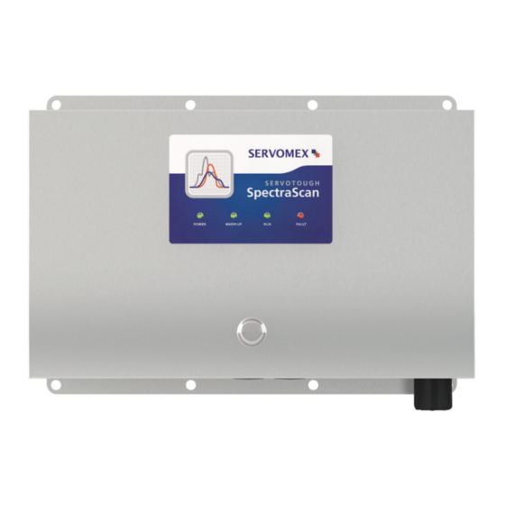
5 MOUNTING CONSIDERATIONS Environmental Requirements The following considerations are described in this section: Dimensions, Weight and Ventilation Operating Temperature, Humidity and Pressure Combustion Hazard Power Requirements Fittings Requirements Figure 1 - The Servomex SpectraScan Gas Analyzer 02400001A/1... -
Page 26: Dimensions, Weight And Ventilation
Figure 2 - Hole Dimensions of the Servomex SpectraScan Gas Analyzer See Figure 3 - I/O panel of the Servomex SpectraScan Gas Analyzer on page 24 for a view of the bottom of the analyzer, showing electrical and pipe connections. -
Page 27: Operating Temperature, Humidity And Pressure
5.0.2 Operating Temperature, Humidity and Pressure The Servomex SpectraScan Gas Analyzer can operate in a wide range of ambient temperature and humidity, as shown in Table 14 - Environmental Specifications on page 72. The analyzer should be operated in a non-condensing environment to avoid condensation on the optical windows in the gas cell. -
Page 28: Combustion Hazard
Section 7 SAMPLE GAS CONNECTIONS on page 49. Other fitting sizes and styles are available from Servomex to be installed on the inlet and exhaust ports as a special order. The underlying connector is a ¼” NPT. - Page 29 2. Consider the order of installation: mount the analyzer onto the mounting surface first; then make electrical connections inside the box with the cover open. 3. Place the Servomex SpectraScan Gas Analyzer on the mounting structure and align the eight mounting holes with holes in the structure. Support the analyzer if necessary.
- Page 30 SERVOTOUGH SpectraScan User Manual This page intentionally left blank. 02400001A/1...
-
Page 31: Electrical Connections
Communication over Ethernet TCP/IP NOTE The Servomex SpectraScan Gas Analyzer must be mounted with eight 3/8”- 16 x 1” UNC bolts and matching lock washers and nuts. WARNING Personal Injury or Death: Wiring of the analyzer must be in accordance with local regulations. -
Page 32: I/O Panel Layout
SERVOTOUGH SpectraScan User Manual I/O Panel Layout Figure 3 - I/O panel of the Servomex SpectraScan Gas Analyzer NOTE The sample, power and signal connections require at least 6” of clearance for safe operation. Circle in the figure above identifies the conduit fitting through which the power, communication and external stream switching solenoid valve cables are to be connected. -
Page 33: Figure 4 - Analyzer With Cover Open
SERVOTOUGH SpectraScan User Manual Figure 4 - Analyzer with Cover Open 02400001A/1... -
Page 34: Component Layout
SERVOTOUGH SpectraScan User Manual 6.0.1 Component Layout Figure 5 - Interior of the Servomex SpectraScan Gas Analyzer NOTE See Figure 6 for detail of SpectraScan internal components 02400001A/1... -
Page 35: Figure 6 - Spectrascan Interior Diagram
SERVOTOUGH SpectraScan User Manual Display Ground Lug Enclosure Lid Cable Spare Enclosure Fuse Fuses Plate AC Power Module (optional) Circuit Board Earth Motor Assembly Ground Power Terminal Sensor Head Block (in blue cover & TCP/IP partially beneath Jack plate and circuit Light Source board) (beneath blue... -
Page 36: Electrical Power Requirements
SERVOTOUGH SpectraScan User Manual Electrical Power Requirements The Servomex SpectraScan Gas Analyzer operates at 24 VDC or 100-240 VAC depending on the model configuration. Be sure to adhere to the Power Rating Label on the analyzer to determine which power source to use, and connect the correct power source. -
Page 37: Wiring
SERVOTOUGH SpectraScan User Manual Wiring All cables entering the analyzer (24 VDC or 120/240 VAC power and communication) must be separately jacketed as they enter the analyzer to prevent miss-wiring. The power cabling used, whether for 24 VDC operation, or for 120-240 VAC operation, must use a 3 conductor cable. The ground wire in this 3 conductor cable must be electrically connected to the earth ground lug in the analyzer. -
Page 38: Power Wiring: 24 Vdc
SERVOTOUGH SpectraScan User Manual 6.2.1 Power Wiring: 24 VDC Figure 8 - Wiring the SpectraScan with 24 VDC 02400001A/1... - Page 39 Make sure that the power is not on (wires are not live) at this point. WARNING Maintain Ingress Protection: The Servomex SpectraScan unit has been tested to an Ingress Protection level of IP66, Type 4. In order to maintain this rating, a suitable 1”...
-
Page 40: Power Wiring: 120-240 Vac
SERVOTOUGH SpectraScan User Manual 6.2.2 Power Wiring: 120-240 VAC Figure 9 - Wiring the SpectraScan with 120-240Vac 02400001A/1... - Page 41 Make sure the wires are not live at this point. WARNING Maintain Ingress Protection: The Servomex SpectraScan unit has been tested to an Ingress Protection level of IP66, Type 4. In order to maintain this rating, a suitable 1” conduit connector must be used that will not compromise the existing IP Rating.
-
Page 42: Communication Connection
SERVOTOUGH SpectraScan User Manual Communication Connection Figure 10 - Connecting the Ethernet TCP/IP communication cable 02400001A/1... - Page 43 3. Bring the communication cable into the enclosure through the conduit fitting. WARNING Maintain Ingress Protection: The Servomex SpectraScan unit has been tested to an Ingress Protection level of IP66, Type 4. In order to maintain this rating, a suitable 1” conduit connector must be used that will not compromise the existing IP Rating.
-
Page 44: Spectrascan Networking And Software Configuration
SERVOTOUGH SpectraScan User Manual Spectrascan Networking and Software Configuration 6.4.1 Ethernet and TCP/IP Getting an IP address using DHCP As delivered, the instruments are configured as DHCP clients. This means each instrument's IP addresses given to it by an external DHCP server, typically a router running on your network. The IP address is assigned dynamically when the instrument is powered up. -
Page 45: Setting A Static Ip Address
Connecting to the system board via RS-232 requires the following items: Windows PC A special serial cable from Servomex. On one end this cable is terminated by a connector mating to the RS-232 connector on the system board. On the other end, the cable is terminated by a DB-9 connector. -
Page 46: Figure 12 - Location Of Debug Rs-232 Connector On Mpu
SERVOTOUGH SpectraScan User Manual Figure 12 - Location of debug RS-232 connector on MPU Connect a Windows PC to the MPU debug connector using the SpectraScan RS-232 cable (and an RS-232 to USB converter, if required). On your PC, determine which COM port is associated with the serial connection. Do this by opening the Windows device manager and looking at the COM port configuration. - Page 47 SERVOTOUGH SpectraScan User Manual 11 .Next, you will be prompted for the desired gateway address. Enter it using the DD.DD.DD.DD format. 12. Next, you will be prompted for the desired broadcast address. Enter it using the DD.DD.DD.DD format. 13 .Finally, you will be asked to reboot and accept the changes, or to cancel. If you have entered all information correctly, choose reboot.
-
Page 48: Rs-422 Connection
SERVOTOUGH SpectraScan User Manual Figure 13 - Sample session in which a static IP address is set using PuTTY to communicate with the MPU. 6.4.4 RS-422 connection The RS-422 link uses a 4-wire connection, 2 wires for receive and 2 wires for transmit. The RS-422 port supports only a point-to-point link. -
Page 49: Figure 14 - Identification Of Rs-422 Signals In Instrument
SERVOTOUGH SpectraScan User Manual Figure 14 - Identification of RS-422 signals in instrument This is shown in Illustration 4. Connect the cable to the individual push-down connectors as shown in the figure. (NOTE: Although the board label says “RS-485”, this port will not function in multi- drop bus mode. -
Page 50: Modbus Register
SERVOTOUGH SpectraScan User Manual 6.4.5 Modbus register The SpectraScan communicates to the external controller via Modbus. The instrument acts as a Modbus server, the external controller is the client. Modbus runs either over RS-422 or Ethernet interfaces. The instrument is configured in the following way: ... -
Page 51: Sample Gas Connections
SERVOTOUGH SpectraScan User Manual 7 SAMPLE GAS CONNECTIONS SpectraScan Gas Analyzer 10 Micron Purge Gas Purge Gas Particulate Supply Exhaust Filter Manual Pressure Relief Sample Gas Valve Mechanism Exhaust Zero Gas Supply Sample Gas Zero Manual Solenoid Valve Solenoid Manual Valve Sample Gas Supply Figure 16 –... -
Page 52: Sample Line Connections
SERVOTOUGH SpectraScan User Manual Sample Line Connections 7.0.1 Sampling Ports Both sample intake and exhaust ports are fitted with male ¼” Swagelok® compression tube fittings. Only properly mated, female ¼” Swagelok® compression fittings should be used on the sample intake and exhaust lines. CAUTION Equipment Damage: Restricting the gas flow on either the intake or the exhaust side may cause the gas cell to over pressurize, causing damage to the analyzer. -
Page 53: Sampling Gas From A Pressurized Source
It is ultimately the user’s responsibility to ensure a clean sample stream. We recommend an inline 10 micron particulate filter for most applications. Contact Servomex for more information. 02400001A/1... -
Page 54: Stream Switching Using External Solenoid Valves
7.0.5 Stream Switching Using External Solenoid Valves The Servomex SpectraScan Gas Analyzer is equipped with three relays connected to the 24 VDC supply, which may be used to control external solenoid valves for the purpose of stream switching. By default, the first two relays are used for automatic zeroing: upon initiating, a software “zero”... -
Page 55: Figure 18 - Recommended Connections For Inlet Stream Switching
SERVOTOUGH SpectraScan User Manual The diagram below depicts the recommended pipe work and electrical connections to utilize the stream switching relays. Note that solenoid labels “NC” and “NO” denote normally closed and normally open respectively. Solenoid lines 1, 2, 3 and 4 should be connected to the rightmost connector bank on the front-edge of the PCB, to connector ports SOL1, GND, SOL2, and GND respectively, as shown in the diagram below. -
Page 56: Procedure For Connecting The Sample Lines
6. Install/connect stream switching lines and solenoids if applicable. 7. Connect sample supply and exhaust lines to the Servomex SpectraScan sample inlet and exhaust ports. 8. Ensure proper sample gas and zero gas temperature and conditioning. In general, sample conditioning is application dependent, see the Application data for more specific information. -
Page 57: Enclosure Purge Connections
SERVOTOUGH SpectraScan User Manual Enclosure Purge Connections 7.1.1 Purging of Enclosure Compartment Certain installations may require the use of purge gas to flow through the enclosure. There are two female ¼” NPTF ports located on the analyzer for this purpose. (See Figure 3). To add a purge to the enclosure, remove the plugs installed at the factory on the purge inlet and purge outlet ports (either port can be used for inlet or outlet). - Page 58 SERVOTOUGH SpectraScan User Manual This page intentionally left blank. 02400001A/1...
-
Page 59: Installation Checklist
SERVOTOUGH SpectraScan User Manual 8 INSTALLATION CHECKLIST The following list gives a brief summary of all the steps needed to correctly install the Servomex SpectraScan Gas Analyzer. It is not a substitution of the procedures, precautions and hazard definitions that appear elsewhere in this document. - Page 60 SERVOTOUGH SpectraScan User Manual This page intentionally left blank. 02400001A/1...
-
Page 61: Verification
SERVOTOUGH SpectraScan User Manual 9 VERIFICATION The purpose of this procedure is to verify span accuracy upon installation of the Servomex SpectraScan Gas Analyzer. This procedure is also performed at periodic intervals throughout the effective life of the unit. This procedure has three parts: Setup, Zeroing and Span Verification. -
Page 62: Zeroing
SERVOTOUGH SpectraScan User Manual 9.0.2 Zeroing Stream Switching Using External Solenoid Valves on page 52 for information on controlling the external valves. 1. Purge the cell with the appropriate zero gas: turn off the sample gas and turn on the zero gas (through software). -
Page 63: Maintenance
SERVOTOUGH SpectraScan User Manual 10 MAINTENANCE The Servomex SpectraScan Gas Analyzer is designed to be maintenance free for extended periods of time. In a normal installation, it will operate unattended in its intended environment for 18 months with no physical intervention. Typically every 18 months, the spectrometer light source needs to be replaced. -
Page 64: Light Source Assembly Replacement Procedure
3. Expose the light source assembly from underneath the blue bag: Refer to Figure 5 - Interior of the Servomex SpectraScan Gas Analyzer on page 33 to identify the location of the light source assembly. -
Page 65: Figure 19 - Accessing The Light Source
SERVOTOUGH SpectraScan User Manual Figure 18 - Accessing the Light Source 5. Remove the connector with the green wires from the bottom edge of the light source circuit board as shown in Figure 19. The black connector has a squeeze tab to prevent accidental release of the connector. -
Page 66: Figure 22 - Mounting Hole For Light Source
SERVOTOUGH SpectraScan User Manual Figure 20 - The Light Source Assembly 8. Apply heat sink around the perimeter of the new light source, and push the assembly back into the mounting hole provided on the sensor head, making sure to orient it properly (connector end toward I/O panel). - Page 67 SERVOTOUGH SpectraScan User Manual 13. Turn on power and gas supply. 14. Wait for at least 30 minutes and until the cell temperature stabilizes at the set operating temperature (indicated by the green “Run” light on the display). 15. Perform Verification (refer to Section 9 Verification). 02400001A/1...
- Page 68 SERVOTOUGH SpectraScan User Manual This page intentionally left blank. 02400001A/1...
-
Page 69: Troubleshooting
SERVOTOUGH SpectraScan User Manual 11 TROUBLESHOOTING See Table 6 - Diagnostic LED Indications for a general description of each indicator status. Below are some common problems/symptoms and possible causes. Problem Possible cause(s) Power LED not lit No or insufficient power. Check Fuse Warm-up light still lit after 2 hours of warm up Environment is too cold to allow stabilization at period... - Page 70 SERVOTOUGH SpectraScan User Manual This page intentionally left blank. 02400001A/1...
-
Page 71: Appendix A: Product Specifications
SERVOTOUGH SpectraScan User Manual 12 APPENDIX A: PRODUCT SPECIFICATIONS 12.0 Measurement Specifications Measurement Light absorption spectroscopy Technique Gas Cell Volume / Path 100 mL / 35 cm Length Zero Drift <0.2% of full scale (FS) per month (typical) Intrinsic Error <1% FS (typical). -
Page 72: Physical Specifications
SERVOTOUGH SpectraScan User Manual 12.1 Physical Specifications Figure 22 - Dimensions of SpectraScan Size 17.25”x 12” x 7” deep Weight 28 lbs. (14 kg) Installation Wall Mounted See Dimensions, Weight and Ventilation on page 24 for installation considerations Vibration Resistant to low amplitude vibration Immunity Table 9 –... -
Page 73: Sampling System Specifications
0 to 50°C (32 to 122°F) standard Allowable Sample 5 to 95% rH non-condensing Temperature and Humidity Contact Servomex for higher temperature requirement Nickel plated or anodized aluminium gas cell, (stainless steel gas cell is optional) Material Of Wetted Parts... -
Page 74: Electrical Specifications
SERVOTOUGH SpectraScan User Manual 12.4 Electrical Specifications Power Rating and Fuse Information Base Input Power 24 Vdc, 5.0 A max Optional Input Power 100-240 Vac (+/-) 10%, 50-60 Hz, 3.0 A max* Fuse (24Vdc replaceable) 125V, 10A Table 13 - Electrical Specifications Table 4 - Wire Types *See on page 35 for important wire rating information. -
Page 75: Index
SERVOTOUGH SpectraScan User Manual 13 INDEX combustion hazard, 26 allowable gas cell, 71 communication requirements, 70 purging, 55 connections regulation, 12 communication, 40 sample electrical, 29 cleanliness, 51 plumbing, 41–55 ports, 51 power, 34 pressurized source, 51 solenoid relays, 53 solenoids, 52 wire types, 35 specifications... -
Page 76: Contact Details
TN6 3FB United Kingdom TEL +44 (0)1892 652181 Fax +44 (0)1892 662253 www.servomex.com NOTE All analyzers returned to Servomex or one of its appointed agents for servicing, or any other purpose must be accompanied by a completed decontamination certificate. 02400001A/1...
Need help?
Do you have a question about the Servotough SpectraScan 2400 and is the answer not in the manual?
Questions and answers