
Related Manuals for Servomex SERVOPRO Chroma


Summary of Contents for Servomex SERVOPRO Chroma
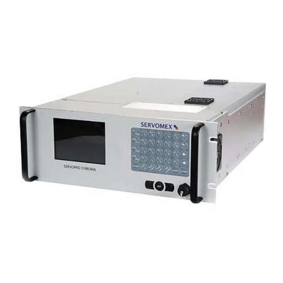
- Page 1 SERVOPRO Chroma Trace Gas Analyser User Manual Part Number: 04400/001 Revision: Language: UK English...
- Page 2 This page intentionally blank...
-
Page 3: Table Of Contents
Page Description and Definitions ..................8 Scope of this manual................... 8 Safety information ....................8 Description......................9 1.3.1 Servopro Chroma Complete Rear Connector ..........9 1.3.2 Servopro Chroma Reduced Rear Connector..........10 1.3.3 FID Modification ..................11 1.3.4 Auxiliary Oven Rear Connecton............... 11 1.3.5... - Page 4 7.2.2 Master chassis connection................. 90 7.2.3 Slave chassis connection................91 7.2.4 Stand alone PC with slave chassis ............92 Connecting Servopro Chroma rear connector........... 93 7.3.1 Digital input ....................93 7.3.2 Digital output contacts ................94 7.3.3 4-20 mA outputs ..................95 7.3.4...
- Page 5 SERVOPRO CHROMA Gas Analyser Gas installation....................98 7.4.1 Introduction....................99 7.4.2 Carrier Gas Hardware Selection ............. 100 7.4.3 Connecting the Servopro Chroma............101 General Operation....................102 Routine maintenance..................102 Storage and Disposal....................103 Storage ......................103 Disposal......................103 Compliance ......................104 FID Addendum ....................
- Page 6 SERVOPRO CHROMA Gas Analyser LIST OF TABLES Table name Page Table 1 : General Specification..................21 Table 2 : Gas Specification ....................21 Table 3 : Oven specification ..................... 22 Table 4 : Environmental limits ..................22 Table 5 : Digital relay outputs ..................22 Table 6 : 4-20 mA outputs ....................
- Page 7 SERVOPRO CHROMA Gas Analyser LIST OF FIGURES Figure name Page Figure 1 : Servopro chroma complete rear connection............9 Figure 2 : Servopro chroma reduced rear connection............10 Figure 3 : FID Modification....................11 Figure 4 : Auxiliary oven rear connection ................ 11 Figure 5 : Standalone PC rear connection.................
- Page 8 SERVOPRO CHROMA Gas Analyser Figure 43 : Remote control menu ..................84 Figure 44 : About menu ....................85 Figure 45 : Chromatogram saving menu ................86 Figure 46 – Master chassis electrical connections............90 Figure 47 – Master and slave chassis electrical connections..........91 Figure 48 –...
-
Page 9: Description And Definitions
1.2 Safety information Read this manual and ensure that you fully understand its content before you attempt to install, use or maintain the Servopro Chroma. Important safety information is highlighted in this manual as WARNINGs and CAUTIONs, which are used as follows. -
Page 10: Description
SERVOPRO CHROMA Gas Analyser 1.3 Description 1.3.1 Servopro Chroma Complete Rear Connector Figure 1 : Servopro chroma complete rear connection This rear panel is present on all master units and on slave units in configurations involving a standalone pc. 1. Power inlet with switch and fuse 12. -
Page 11: Servopro Chroma Reduced Rear Connector
SERVOPRO CHROMA Gas Analyser 1.3.2 Servopro Chroma Reduced Rear Connector Figure 2 : Servopro chroma reduced rear connection This rear panel is present on all slave units in a system which contains a master unit. 1. Power inlet with switch and fuse 9. -
Page 12: Fid Modification
1.3.3 FID Modification Figure 3 : FID Modification When a FID detector is installed in a Servopro Chroma, the rear connector is modified to allow for the different connections required. These modifications are: 1. Carrier inlet 1 is replaced by the FID vent 2. -
Page 13: Standalone Pc Rear Connecton
USB memory stick only. Rear USB port to be used with Keyboard mouse or USB memory stick only. Only keyboard supplied by Servomex shall be used CAUTION To comply with the requirements of the EU EMC Directive, a single turn ferrite (Wurth type 742-711-31) shall be fitted to the RS232 output cable. - Page 14 WARNING Any equipment connected to standalone PC shall be separated by mains voltage by at least double insulation. The Servopro Chroma is a rack-mount type analyser to be used in fixed installations. 04400001A / Revision 2...
-
Page 15: Software License
You may use the software on the device with which you acquired the software. 2. Additional Licensing Requirements and/or Use Rights. a. Specific Use. Servomex designed this device for a specific use. You may only use the software for that use. - Page 16 3. Scope of License. The software is licensed, not sold. This agreement only gives you some rights to use the software. Servomex and Microsoft reserve all other rights. Unless applicable law gives you more rights despite this limitation, you may use the software only as expressly permitted in this agreement.
- Page 17 SERVOPRO CHROMA Gas Analyser For more information, please refer to the device documentation or contact Servomex. • Internet-Based Services. Microsoft provides Internet-based services with the software. Microsoft may change or cancel them at any time. a. Consent for Internet-Based Services. The software features described below connect to Microsoft or service provider computer systems over the Internet.
- Page 18 To be valid, this label must be affixed to the device, or included on or in Servomex’s software packaging. If you receive the label separately, it is not valid. You should keep the label on the device or packaging to prove that you are licensed to use the software.
- Page 19 Any warranties you receive regarding the device or the software do not originate from, and are not binding on, Microsoft or its affiliates. When allowed by your local laws, Servomex and Microsoft exclude implied warranties of merchantability, fitness for a particular purpose and non-infringement.
-
Page 20: Specifications
SERVOPRO CHROMA Gas Analyser 3 SPECIFICATIONS WARNING You must install and use the Servopro Chroma in accordance with the requirements of this section and subsequent sections of the manual. If you do not, the protection facilities incorporated into the design of the Servopro Chroma may not operate as intended, sample gas measurements may not be accurate, or the Servopro Chroma may be damaged. -
Page 21: General
SERVOPRO CHROMA Gas Analyser 3.1 General Master chassis dimensions: Height x width x depth: 178 x 483 x 610 mm (7 x 19 x 24 ins) Slave chassis dimensions: Height x width x depth: 178 x 483 x 610 mm (7 x 19 x 24 ins) -
Page 22: Gas
SERVOPRO CHROMA Gas Analyser Carrier gas pressure rating Minimum (plasma): 630.6 kPa (90 psig) Minimum (FID): 828.6 kPa (120 psig) Maximum: 828.6 kPa (120 psig) Sample gas pressure rating Minimum: 69.0 kPa (10 psig) Maximum: 137.9 kPa (20 psig) Detector type:... -
Page 23: Oven Specification
SERVOPRO CHROMA Gas Analyser 3.3 Oven Specification Chromatographic oven: Maximum temperature 300 ˚C Minimum temperature Ambient Auxiliary oven: Maximum temperature 300 ˚C Minimum temperature Ambient FID Oven: Maximum temperature 100 ˚C Minimum temperature Ambient TCD oven: Maximum temperature 300 ˚C... -
Page 24: Ma Outputs
(18 AWG) Maximum length 30 m Table 7 : Digital inputs 3.8 Hydrogen Relay Output This relay is only available when a FID detector is installed in the Servopro Chroma. Maximum voltage: 24 VDC Maximum current: 1 Amp Cable requirements:... -
Page 25: Ethernet Port
SERVOPRO CHROMA Gas Analyser Table 8 : Hydrogen relay output 3.9 Ethernet Port Cable requirements Standard 10 BaseT Connector type RJ45 (CAT5 UTP) Maximum length 30 m Caution: This cable shall not be routed outside the building in which the analyser is installed without the application of screening or similar protection. -
Page 26: Mains Input Cables (Master/Slave/Stand Alone Pc)
SERVOPRO CHROMA Gas Analyser 3.13 Mains input cables (Master/Slave/Stand alone PC) Type IEC 60320-1-C13 Cable requirements -Screened -Specified for 10 A / 250 Vac -Fit with a main plug that meets the requirement of the country where analyser us used. -
Page 27: System Description
Conductivity Detector), F.I.D. (Flame Emission Detector) and Plasma Emission Detector. When an application asks for it, a Servopro Chroma system can have one or more slave chassis to hold various detectors and columns. A slave chassis has its own electronic system to control detector and data acquisition. -
Page 28: Plasma Cell
Please, in order to appreciate and understand all the features of your Servopro Chroma system, take the time to read and understand all parts of the User’s Manual. If you have any doubt or questions as a customer of Servomex, you may contact us directly for technical support free of charge. - Page 29 SERVOPRO CHROMA Gas Analyser Excitation, in these cases, results mostly from electron or ion collision; that is, the kinetic energy of electrons or ions accelerated in an electric field in which the atoms or molecules of a gas are subjected to, which cause the emission of light.
-
Page 30: Electric And Electronic Hardware Description
4.3.3 Oven heater and control Up to 8 ovens can be installed in the Servopro Chroma main chassis. The temperature electronic control hardware is mounted on the I/O board. There are 8 temperature control loops (PID) in the software. The temperature is measured with a RTD. -
Page 31: I/O Board
SERVOPRO CHROMA Gas Analyser 4.3.4 I/O board The I/O board holds all the I/O functions of the instrument. See following table. Digital I/O 1 isolated digital inputs 8 remote range dry contact outputs 2 alarm dry contact outputs 1 system status dry contact output 1 extra relay 10 G.C. -
Page 32: Unpack The Servopro Chroma
CAUTION You must remove the protective covers as specified in Steps 3 and 4 above before you use the Servopro Chroma. If you do not, you may damage the Servopro Chroma when you try to pass gases through it. 04400001A / Revision 2... -
Page 33: Servopro Chroma User Interface
SERVOPRO CHROMA Gas Analyser 6 SERVOPRO CHROMA USER INTERFACE All analyzer’s functions are controlled through different menus of the user interface in which controls are found. The user has to interact with these controls which are explained in this section. You must become familiar with these. -
Page 34: Slide Control
SERVOPRO CHROMA Gas Analyser 6.1.3 Slide control The slide control is used when the user may choose between items; for example, when the user has to choose between “selected peaks” or “all peaks” in the calibration menu. Figure 8 : Slide control To operate a slide from the keyboard: Press UP to move the slider up one position. -
Page 35: Grid Control
SERVOPRO CHROMA Gas Analyser 6.1.5 Grid control The grid is used to show, change or highlight data. Figure 10 : Grid control To operate a grid from the keyboard: To change a value, enter the new value and change cell. -
Page 36: Check Box Control
SERVOPRO CHROMA Gas Analyser 6.1.7 Check Box control The Check Box control is used to enable a feature. Figure 12 : Check Box control To operate it with the keyboard, press the space key to make it checked (enabled) or unchecked (disabled). -
Page 37: Menu Description
SERVOPRO CHROMA Gas Analyser 6.2 Menu Description The analyzer’s functions are regrouped in menus which are structured as in the following figure. Figure 14 : Menu description 6.2.1 Run 6.2.1.1 Real Time Chromatogram Pressing CTRL-R or clicking Run and then Real Time Chromatogram on the menu bar brings you to the RUN-REAL TIME CHROMATOGRAM MENU (fig. -
Page 38: Figure 15 : Real Time Menu
SERVOPRO CHROMA Gas Analyser Figure 15 : Real time menu The real time chromatogram menu is the main menu of the Servopro Chroma Trace Gas Analyzer software. In this menu, you can start a cycle and visualize the resulting real time chromatogram. This chromatogram takes into account all the peak data that can be configured in the CONFIGURATION-CYCLE MENU. - Page 39 SERVOPRO CHROMA Gas Analyser You may also choose between two injection modes using the Injection mode radio button. If you select Manual, only one cycle is executed after the Start button is pressed. If you choose Automatic, the analyzer restarts new cycles until you press the Stop button or select Manual.
- Page 40 SERVOPRO CHROMA Gas Analyser menu will be explained in detail later. The button is enabled only when no cycle is in progress. The trending can also be zoomed using the mouse. Press the mouse’s left button and keep it down while moving the mouse. A rectangle while appear on the screen to identify the zone to zoom.
-
Page 41: Historic Values Menu
SERVOPRO CHROMA Gas Analyser Push Hot key Function Button Start/ Does an injection and begins a real-time chromatogram or Stop stops a cycle and sets all gas chromatogram valves at their original position. Range In Manual ranging only. Change the operating range. -
Page 42: Alarm Historic Menu
SERVOPRO CHROMA Gas Analyser 6.2.1.1.2 Alarm historic menu Displays the last 200 system alarms, peak value alarms or event logs that occurred and all the current active alarms. See HISTORIC-ALARM MENU description for more details. System alarms: Low sample flow: When the sample flow goes below 10 CC/min with a sample flow set point bigger than 10 CC/min;... - Page 43 When the concentration of impurity is greater than the actual scale of the peak. Peripheral alarms: Some peripherals connected with the Servopro Chroma (FID detector, HPS …) could show their alarms / errors status into the Alarm historic menu. Please, refer to their respective user’s manual for more details.
- Page 44 SERVOPRO CHROMA Gas Analyser Example: • If a “Low carrier flow” occurs, the following message is displayed: (date) Low carrier flow: (hour) • When the flow problem is rectified, the following message is displayed: (date) Low carrier flow: Ok (hour)
-
Page 45: Diagnostic
SERVOPRO CHROMA Gas Analyser 6.2.2 Diagnostic 6.2.2.1 Diagnostic Pressing Diagnostic (CTRL-P) on the menu bar and then on Diagnostic brings you to the DIAGNOSTIC-DIAGNOSTIC MENU (fig. 11). The system diagnostic menu can be used for troubleshooting or only for information about the system. - Page 46 SERVOPRO CHROMA Gas Analyser Data Meaning The cell counts are the detector raw signal. This data is displayed in Cell counts, from 0 to 16777215 and also in volts, from 0 to 5V. The chromatogram signal represents the signal that will be displayed Chromatogram on the chromatogram and used to do the peak integrations.
-
Page 47: Table 15 : Diagnostic Menu
SERVOPRO CHROMA Gas Analyser Shows the temperature in Celsius degrees inside the chassis and outside the chassis of a selected IO Board. If there’s more than one Temperature IO Board into the analyzer, only the inside temperature is shown for the other. -
Page 48: Analyse Chromatogram
SERVOPRO CHROMA Gas Analyser 6.2.2.2 Analyse Chromatogram Pressing CTRL-L or clicking on Diagnostic on the menu bar and then on Analyse Chromatogram brings you to the DIAGNOSTIC-ANALYSE CHROMATOGRAM MENU (fig. 12). Figure 17 : Analyse chromatogram The analyse chromatogram menu is used when you need to analyse a chromatogram and define the right starting and ending times for the peaks. - Page 49 SERVOPRO CHROMA Gas Analyser you want to observe. Pressing the Undo Zoom (F8) button will display the original chromatogram. When you visualize a real time chromatogram, you cannot differentiate each conditioning board, you only get one line on the graph. But with a trending, each conditioning board read in the DIAGNOSTIC-TRENDING MENU can be seen with a different colour.
-
Page 50: Table 17 : Configuration Menu
SERVOPRO CHROMA Gas Analyser Push Button Hot key Functions Set Position #1 Set time and counts for the position #1 Set Position #2 Set time and counts for the position #2 Undo Zoom Resizes the trending to the normal size. -
Page 51: Trending
SERVOPRO CHROMA Gas Analyser 6.2.2.3 Trending Pressing CTRL-T or clicking on the menu bar Diagnostic and then on Trending brings you to the DIAGNOSTIC-TRENDING MENU (fig. 13). Figure 18 : Trending menu The trending menu is useful when you need to find peaks and set the proper settings for each of them, i.e. -
Page 52: Figure 19 : Trending Menu Valve State
SERVOPRO CHROMA Gas Analyser You can change the generator power by pressing Generator Power (F3) button. A Pop-Up will ask you a value between 0 and 100% for each generator in the analyzer. You can do a Re-Zero for the detector indicated in the edit box control beside the Re-Zero (F4) button. -
Page 53: Table 18 : Trending Menu
SERVOPRO CHROMA Gas Analyser When the Active Detector tab of the left-bottom grid is selected, all configurations for each detector are shown. In the Det. # column, you can select the detector that you want to trend on the graph. A check box marked means that the detector will be trend. -
Page 54: Advanced Diagnostic
SERVOPRO CHROMA Gas Analyser 6.2.2.4 Advanced Diagnostic Clicking Diagnostic on the menu bar and then Advanced Diagnostic brings you to the DIAGNOSTIC-ADVANCED DIAGNOSTIC MENU (fig. 15). This menu is used to trigger different components of the analyzer. Figure 20 : Advanced diagnostic menu 1) 4-20 mA Diagnostic: This section is used to manually control the 4 to 20 mA analogue outputs. - Page 55 SERVOPRO CHROMA Gas Analyser 2) Relay Diagnostic: This section is used to verify if the Range relays on the I/O Boards are working properly. First select the I/O Board to diagnose by using the combo box just under the title “Relay Diagnostic”. By using the combo box in the state column of the grid, you can switch the relay ON or OFF depending on the configuration in CONFIGURATION-ADVANCED CONFIGURATION MENU.
-
Page 56: Configuration
SERVOPRO CHROMA Gas Analyser 6.2.3 Configuration 6.2.3.1 System Pressing CTRL-S or by clicking Configuration on the menu bar and then System brings you to the CONFIGURATION-SYSTEM MENU (fig. 16). The system configuration menu is another very important menu. Many parameters are set there. - Page 57 SERVOPRO CHROMA Gas Analyser 3) Generator Starting mode: • Manual: the automatic re-start feature is disabled and you may enter any plasma power value between 0 and 100%. It is useful when troubleshooting or re-configuring the system. • Automatic: when the cell raw counts are lower than the cell Plasma starting count value, a higher power will be applied to the cell to restart the plasma.
-
Page 58: Table 19 : Unregulated Flow
Servopro Chroma. If the actual flow is 2 CC/min lower or 2 CC/min higher than the reference, the flow deviation alarm is added in the ALARM HISTORIC and the contact status is opened (or closed, depending the configuration in the CONFIGURATION-ALARM MENU). - Page 59 13) Change password This button is used to set a new password for the Servopro Chroma. This password is used when you want to quit the software or access the CONFIGURATION-ADVANCED MENU.
-
Page 60: Pid
Clicking on Configuration on the menu bar and then on Flow brings you to the CONFIGURATION-FLOW MENU (fig. 18). This menu contains the flow sensor table. This data is set up by Servomex. If you have to recalibrate some of these data, follow these steps:... -
Page 61: Figure 23 : Unregulated Flow Configuration Menu
SERVOPRO CHROMA Gas Analyser note the Flow meter counts in the Flow Setting Tool. Use a bubble flow meter to find the reading of the flow in CC and write down these two values on paper. When you have 10 reading points, you must enter these in the flow table using the keyboard. -
Page 62: Table 21 : Flow Factor
ADVANCED MENU to know which flow is a regulated flow and which is a unregulated flow. Flow Factor: Many different types of gases could be handled by the Servopro Chroma. Flow transducers use the thermal conductivity principle to determine the volumetric flow (CC/min) of the gas. Various gases have different conductivities, for example, Helium and Hydrogen have a much higher thermal conductivity compared to Argon or Oxygen. - Page 63 SERVOPRO CHROMA Gas Analyser The minimum pressure required for proper operation could need to be re-adjusted in order to avoid oscillation of the flow control loop when changing the sample gas type. This is application dependent. The sample flow factor can be determined by using a bubble flow meter on the sample vent.
-
Page 64: Cycle
SERVOPRO CHROMA Gas Analyser 6.2.3.4 Cycle Clicking on Configuration on the menu bar and then on Cycle brings you to the CONFIGURATION-CYCLE MENU (fig. 20). This menu contains all the information that the system needs when a cycle (Real time chromatogram) is in progress. -
Page 65: Figure 26 : Peak Configuration Menu
SERVOPRO CHROMA Gas Analyser 2) Peak: Peak Configuration: The data that is found in the next menu is used during an analysis. The system parameters change in real time according to each peak configuration. Figure 26 : Peak configuration menu In the grid at the top of this menu, you found general information that does not depend upon the kind of detector. -
Page 66: Table 22 : Peak Configuration Columns
SERVOPRO CHROMA Gas Analyser Alarm 2 When the peak exceeds this value, the alarm 2 will be activated. Range 2 (Range 2 Scale) This value indicates the full scale of the analyzer (Range 2). Range 1 (Range 1 factor) The multiplier applied to the system, when the analyzer is on the first range. -
Page 67: Figure 27 : Peak Detection Configuration Menu
SERVOPRO CHROMA Gas Analyser Peak Detection: In this menu, you can modify constant that are used to detect if and when there is a peak. Figure 27 : Peak detection configuration menu AVOID CHANGING THESE SETTINGS: they are configured in factory by Servomex. -
Page 68: Figure 28 : Valve Configuration Menu
SERVOPRO CHROMA Gas Analyser 3) Valve data: Figure 28 : Valve configuration menu This group box is used to control the valve state. By clicking in the combo box, you can change the time at which the valve go ON (open) or OFF (close). Each row in the grid indicates a sequence for the selected valve. -
Page 69: Figure 30 : Flow Timing Configuration Menu
SERVOPRO CHROMA Gas Analyser 4) Flow This group box is used to configure flow timing table. A flow timing table can be used to change a flow set point during a cycle. Figure 30 : Flow timing configuration menu To set a flow timing table, select the proper flow name using the combo box. -
Page 70: Date And Time
SERVOPRO CHROMA Gas Analyser 6.2.3.5 Date and Time Clicking on Configuration on the menu bar and then on Date and Time brings you to the CONFIGURATION-DATE AND TIME MENU (fig. 26). Figure 31 : Date and Time menu This menu lets you set the date and time of your analyzer. By using the combo box control, you can change the value of the date and of the time. -
Page 71: Advanced Configuration
CONFIGURATION-ADVANCED MENU (fig. 27). This menu is the analyzer core. It defines all the hardware components on which the Servopro Chroma is built. Therefore, you normally don’t have to change these configurations; they are set in factory and reflect the hardware of the analyzer. - Page 72 SERVOPRO CHROMA Gas Analyser In this menu, all Servopro Chroma alarm and error monitoring can be turned off when a user wants to work with the analyzer even if for example a flow is too low for a proper operation.
-
Page 73: Figure 33 : Detector Configuration Menu
SERVOPRO CHROMA Gas Analyser 2) Detector Association: Figure 33 : Detector configuration menu When using a plasma cell, a conditioning board must also be selected with the right channel. Moreover, a plasma detector must be associated to the cell by selecting its location on an IO board and its number on this IO board. -
Page 74: Figure 34 : Advanced Flow Configuration Menu
SERVOPRO CHROMA Gas Analyser 3) Flow: Figure 34 : Advanced flow configuration menu The Flow menu associates a flow with a sensor on a certain I/O Board or Pressure Board. Name the flow, choose its location on the appropriate I/O Board, select Sensor number 3, 4 or 5 for a carrier, and associate a plasma detector (used to generate alarms and errors). -
Page 75: Figure 35 : Advanced Valve Configuration Menu
SERVOPRO CHROMA Gas Analyser 4) Valve: Figure 35 : Advanced valve configuration menu The Valve menu associates a valve number to a valve channel on an I/O Board. 04400001A / Revision 2... -
Page 76: Figure 36 : Advanced Oven Configuration Menu
SERVOPRO CHROMA Gas Analyser 5) Oven: Figure 36 : Advanced oven configuration menu The Oven menu associates an oven with a certain I/O Board and a certain channel on this IO board. It is also possible to enter the maximum and minimum value for the temperature set point of this oven. -
Page 77: Alarm
SERVOPRO CHROMA Gas Analyser 6.2.3.7 Alarm Clicking on Configuration on the menu bar and then on Alarm brings you to the CONFIGURATION-ALARM MENU (fig. 32). Figure 37 : Alarm outputs configuration menu This menu lets you configure the alarms. The status alarm relay can be closed or opened when a status alarm is activated. -
Page 78: Printers
SERVOPRO CHROMA Gas Analyser 6.2.3.8 Printers Clicking on Configuration on the menu bar and then on Printers brings you to the PRINTER CONFIGURATION MENU (fig. 33). Figure 38 : Printers configuration menu The printers already installed on your analyzer will be listed in this menu. It is possible to configure a new printer by adding it with the Add Printer button. -
Page 79: Calibration
SERVOPRO CHROMA Gas Analyser 6.2.4 Calibration 6.2.4.1 Calibration By clicking Calibration on the menu bar and then Calibration, you access the CALIBRATION-CALIBRATION MENU (fig. 34). Figure 39 : Calibration menu This menu is used to calibrate the system for the different gases you have to analyze. -
Page 80: Figure 40 : Span Calibration Menu
SERVOPRO CHROMA Gas Analyser First, you need to enable the Noise Threshold Calibration with the corresponding Enable button. After a few cycles in automatic injection, you can press Calculate Threshold button. The RMS value will be shown in the THRSH column of the grid. - Page 81 SERVOPRO CHROMA Gas Analyser the analyzer results will be more accurate. Once calibration values have been entered, click OK to go back to Calibration main menu. If you have more than one peak, do the same steps for the remaining peaks. Once all values are set, a calibration cycle can be performed.
-
Page 82: Calibration Of The 4-20Ma Outputs
SERVOPRO CHROMA Gas Analyser Calculate Threshold, ReSpan and Start buttons are only accessible when calibration is enabled. The other values displayed on the grid are: - Area counts: this is the area that covers the peak in counts (digital converter units). - Page 83 SERVOPRO CHROMA Gas Analyser ► Step 1: First choose the IO board on which you want to calibrate the 4- 20mA outputs; normally, the 4-20mA outputs are on the first IO board; ► Step 2: Select the output you want to calibrate;...
-
Page 84: Remote
Set Static Parameter (F3) button. The Disconnect button is there if you want to close the communication between the Servopro Chroma and the PC Software. If you close the Servopro Chroma 04400001A / Revision 2... -
Page 85: Remote Control
Figure 43 : Remote control menu In this menu, you are able to set the network port number on which the remote control software will communicate with the Servopro Chroma and the password used for the login connection. 04400001A / Revision 2... -
Page 86: About
In this menu, you have the software version of the user interface (PC), the firmware versions of the embedded electronic boards and information about the memory usage. This information can be very useful if you have to contact Servomex support. 04400001A / Revision 2... -
Page 87: Chromatogram Saving
SERVOPRO CHROMA Gas Analyser 6.2.7 Chromatogram saving In version 2.6.3, a new feature was added to store chromatogram on the internal hard drive. This feature can be configured from menu Historic/Chromatogram. To enable this feature, the check box must be selected. When selected, chromatogram will be saved at the end of each cycle. -
Page 88: Quit
After a quit is done, wait for the black screen and then turn the analyzer power supply off with the switch on the back of the Servopro Chroma. When clicking on the Quit button, the analyzer will ask you for the general password of this analyzer. -
Page 89: Installation And Setup
SERVOPRO CHROMA Gas Analyser 7 INSTALLATION AND SETUP 7.1 System power up If your system has slave chassis, they must be powered on before the master chassis. If your system has an external PC, start all chassis and finally power on the PC. - Page 90 SERVOPRO CHROMA Gas Analyser • When you carry out insulation testing, disconnect all cables from the analyser. • Ensure the analyser is provided with a sound earth connection via the electrical supply plug. 04400001A / Revision 2...
-
Page 91: Master Chassis Connection
SERVOPRO CHROMA Gas Analyser 7.2.2 Master chassis connection The following drawing explains how to connect the different parts of a Servopro Chroma system that only have one slave chassis. The master chassis must be connected to a power source using a properly rated cable (see section 3.13). If an auxiliary oven is required for your application, connect the cable coming out of the auxiliary oven to the connector named “Auxiliary oven”... -
Page 92: Slave Chassis Connection
SERVOPRO CHROMA Gas Analyser 7.2.3 Slave chassis connection The following drawing explains how to connect the different parts of a Servopro Chroma system that have master and slave chassis. The master and slave chassis must be connected to a power source using properly rated cables (see section 3.13). If an auxiliary oven is required for your application, connect the cable coming out of the auxiliary oven to the connector named “Auxiliary oven”. -
Page 93: Stand Alone Pc With Slave Chassis
SERVOPRO CHROMA Gas Analyser 7.2.4 Stand alone PC with slave chassis The Servopro Chroma can be supplied with a stand alone PC depending on the application. The stand alone PC must always be connected to the same protective earth as... -
Page 94: Connecting Servopro Chroma Rear Connector
7.3 Connecting Servopro Chroma rear connector 7.3.1 Digital input Servopro Chroma has one digital input that is used to start an analysis remotely. Connection between Servopro Chroma and Remote system is made with a shielded twisted cable. In case of fuse failure, change fuse F12, referring to section 7.3.1. -
Page 95: Digital Output Contacts
SERVOPRO CHROMA Gas Analyser 7.3.2 Digital output contacts Servopro Chroma can have up to 12 digital outputs. All those outputs are dry contacts. No power is provided by those outputs. They all connected to a common port and fused. Connection between Servopro Chroma is made using a shielded multi core cable. In the case of fuse failure, change fuse F14, referring to section 7.3.1. -
Page 96: Ma Outputs
Figure 44 represents the circuit of Servopro Chroma 4-20 mA. The connection between the Servopro Chroma and the monitoring system must be done using a shielded twisted cable. Connect the load resistor on the monitoring system. A differential input must be used on the data acquisition system to properly monitor the data. -
Page 97: Fid Fuel Shut-Off Relay/Hydrogen Relay Output
A fuel shut-off valve can be connected to the rear connector of the analyser. This valve must be normally closed. This valve is controlled by the Servopro Chroma software. When an error occurs, it closes this valve automatically to prevent the accumulation of fuel inside the Servopro Chroma. -
Page 98: Port
The Servopro Chroma has a RS-485 port. This port is only used to communicate with other Servopro Chroma systems. It is not design to be used to interface with third party systems. If your system has multiple chassis, you need to connect them using shielded D- sub HD15 Male/Male cable. -
Page 99: Gas Installation
SERVOPRO CHROMA Gas Analyser 7.4 Gas installation WARNING It is of the highest importance to never pressurize the analyzer because the quartz cell would be irreversibly damaged. So, before supplying any gas to the instrument, first remove the caps on the vent connections. -
Page 100: Introduction
SERVOPRO CHROMA Gas Analyser 7.4.1 Introduction The sampling system is the most important part of your analytical system. The performance of your analyzer can be dramatically limited by your gas transporting system. What we mean, by gas transporting system, any pressure regulator, valve, line, fitting, filter, purifier, etc. -
Page 101: Carrier Gas Hardware Selection
The cost of UHP grade argon cylinders is inexpensive compared to carrier or research grade. The purifier will last many years. Gas Purifier You can buy such purifier from Servomex’s representatives The model number to order is: GP-200- 120: 120 VAC GP-200- 240: 240 VAC You must add the proper model definition digits for supply voltage and fittings type. -
Page 102: Connecting The Servopro Chroma
SERVOPRO CHROMA Gas Analyser 7.4.3 Connecting the Servopro Chroma 1. Once Servopro Chroma installed in a cabinet or rack, remove all caps. It is very important because avoiding removing caps on the outlet will damage the plasma cell. 2. Connect all carrier gas inlets. Make sure that pressure are according to specifications and that lines were properly purged. -
Page 103: General Operation
SERVOPRO CHROMA Gas Analyser 8 GENERAL OPERATION 8.1 Routine maintenance The analyzer does not need a lot of supervision. But for accurate measurements you must be sure that: 1. Carrier flow is as per the value specified for your configuration. To check the carrier flow, put the injection mode in manual. -
Page 104: Storage And Disposal
Refit any protective cover (see Section 5) and place the Servopro Chroma and any associated equipment in its original packing before storage. Store the Servopro Chroma and any associated equipment in a clean, dry area. Do not subject it to excessively hot, cold, or humid conditions: See section 2.5. -
Page 105: Compliance
SERVOPRO CHROMA Gas Analyser 10 COMPLIANCE The analyzer complies with the European Community "Electromagnetic • Compatibility Directive": o Emissions: Class B - Equipment suitable for use in domestic establishments and in establishments directly connected to a low voltage supply which supplies buildings for domestic purposes. -
Page 106: Fid Addendum
SERVOPRO CHROMA Gas Analyser 11 FID ADDENDUM 11.1 Introduction This document explains how to set up and use a FID with the Servopro Chroma software. 11.2 Overview The low noise flame ionization detector (FID) is designed to measure hydrocarbons in the sub ppm level to percentage level. -
Page 107: Menus
SERVOPRO CHROMA Gas Analyser 11.4 MENUS 11.4.1 CONFIGURATION-ADVANCE MENU You normally shouldn’t have to change these configurations; they are set in factory and reflect the hardware of the analyzer. In the menu Advanced Configuration, you can add or remove FIDs by modifying the quantity. -
Page 108: Configuration-Advance Fid Menu
SERVOPRO CHROMA Gas Analyser 11.4.2 CONFIGURATION-ADVANCE FID MENU In this menu you will be able to modify the FID settings. You have to click on save for your modifications to take effect. Figure 54: Advanced FID menu Parameter Range Unit Description Polariz. - Page 109 SERVOPRO CHROMA Gas Analyser Air, Fuel and carrier set points are for the ignition, if you press ignite flame in the Diagnostic menu, the Servopro Chroma will automatically change these set points to ignite flame and it will set back the normal value when the flame is lit.
-
Page 110: Configuration-Advance Detector Menu
SERVOPRO CHROMA Gas Analyser 11.4.3 CONFIGURATION-ADVANCE DETECTOR MENU Figure 55: Advanced detector menu In this menu you will be able to modify the FID detector settings. You have to click on save for your modifications to take effect. Cond. Board: Select on which acquisition board the FID is connected. -
Page 111: Configuration-Advance Flow Menu
SERVOPRO CHROMA Gas Analyser 11.4.4 CONFIGURATION-ADVANCE FLOW MENU This menu gives you the possibility to give a name to each flow associated with the FID. To operate, a FID needs Air, Fuel and Carrier gas. So, pressure regulators associate to these gases must be configured. -
Page 112: Configuration-Advance Oven Menu
SERVOPRO CHROMA Gas Analyser 11.4.5 CONFIGURATION-ADVANCE OVEN MENU The oven menu also works the same way. You can now select FID as a location, and you will be forced to use Channel #1 as the FID only allows configuring its first oven. -
Page 113: Monitoring And Configuration Menus
SERVOPRO CHROMA Gas Analyser 11.4.6 MONITORING AND CONFIGURATION MENUS Throughout the application, the flows and ovens associated with your FID will be showed with the other flows and ovens in your analyzer and you will be able to interact with them in the same way you would interact with the others. -
Page 114: Figure 55: Monitoring Fig 3
SERVOPRO CHROMA Gas Analyser Inside the Trending menu: Figure 60: Monitoring fig 3 Inside the PID Configuration menu: Figure 61: Monitoring fig 4 04400001A / Revision 2... -
Page 115: Figure 57: Monitoring
SERVOPRO CHROMA Gas Analyser Inside the Flow Configuration menu: Figure 62: Monitoring 04400001A / Revision 2... -
Page 116: Diagnostic-Diagnostic Menu
SERVOPRO CHROMA Gas Analyser 11.4.7 DIAGNOSTIC-DIAGNOSTIC MENU In the Diagnostic menu, you will be able to change the FID parameters. You’ll have to click on the FID Board #X tab and then you’ll be able to set its Gain, Offset and Pre-Amp. These values are used in the trending menu. You can also use these values to configure the default values in the Configuration/Cycle menu. -
Page 117: Configuration-Cycle Menu
SERVOPRO CHROMA Gas Analyser 11.4.8 CONFIGURATION-CYCLE MENU In the Cycle menu, you will be able to change the Log Amplifier parameters that are associated to each FID peak. When you have right selected the parameters in the Diagnostic menu, you have to set them in the cycle menu to be sure these parameters will be set on each cycle. -
Page 118: Startup
Note: Those data can be different. See document settings that were sent with your Servopro Chroma. 6. When the flame is lit, the flow set points will come back to there normal values. (Step 4) 7. The Servopro Chroma /FID is ready to use. 04400001A / Revision 2... -
Page 119: System Errors
Air flow reg. problem: A problem appears with air pressure regulator, the system will have to be restarted. If after rebooting, you still have this error, contact Servomex. Fuel flow reg. problem: A problem appears with fuel pressure regulator, the system will have to be restarted. - Page 120 SERVOPRO CHROMA Gas Analyser Every time an error occurs, the status contact relay is closed. Moreover, if you have set the “mA failure mode” to low or high, the 4-20 mA analogue output will be set according to this setting.
-
Page 121: Troubleshooting
SERVOPRO CHROMA Gas Analyser 11.7 Troubleshooting Symptom Problem cause Possible remedy Fuel gas emerging from burner jet diluted with other Purge fuel gas regulator. gases because fuel system is insufficiently purged. Burner doesn’t ignite Air and fuel flow not Adjust air and flow set properly set. -
Page 122: Addendum
SERVOPRO CHROMA Gas Analyser 12 RS-232 ADDENDUM The communication parameters of the analyser are: • Baud rate: 38400 • Parity bits: none • Data bits: • Stop bits: The following tables describe the command set: 12.1 Start analysis K4000 Request / Command... -
Page 123: Send Results
SERVOPRO CHROMA Gas Analyser 12.3 Send results K4000 Request / Command Response Character Character ASCII Code ASCII Code Character No (hex) Character No (hex) Meaning > Command ID 0 = Failure, 1 = Success (If failure, jump to Char no 154 (checksum))*... -
Page 124: Enable-Disable Calibration
SERVOPRO CHROMA Gas Analyser 12.4 Enable-Disable Calibration K4000 Request / Command Response Character ASCII Code Character ASCII Code No (hex) No (hex) Character Character Meaning > > Command ID Success 30h or 31h 0 or 1 (0 = disable / 1 = enable) -
Page 125: Product Disposal In Accordance With The Waste Electrical And Electronic Equipment (Weee) Directive
WEEE Directive, contact Servomex at info@servomex.com or your local Servomex agent • If you send the analyser to Servomex or your local Servomex agent for disposal, the analyser must be accompanied by a correctly completed decontamination certificate.
Need help?
Do you have a question about the SERVOPRO Chroma and is the answer not in the manual?
Questions and answers