Servomex SERVOTOUGH 1900 Digital Operator's Manual
Gas analyser
Hide thumbs
Also See for SERVOTOUGH 1900 Digital:
- Quick start manual (21 pages) ,
- Quick start manual (29 pages)

Related Manuals for Servomex SERVOTOUGH 1900 Digital


Summary of Contents for Servomex SERVOTOUGH 1900 Digital
- Page 1 SERVOTOUGH 1900 Digital Gas Analyser Operator Manual Part Number: 01910001A Revision: Language: UK English...
- Page 2 This page intentionally blank...
- Page 4 This page intentionally blank.
-
Page 5: Table Of Contents
1900 Digital O Gas Analyser LIST OF CONTENTS Section Page DESCRIPTION AND DEFINITIONS......1 Scope of this manual ........1 Safety information. - Page 6 1900 Digital O Gas Analyser CONTENTS (CONTINUED) Section Page GENERAL OPERATION ....... . 35 Calibrating the analyser .
- Page 7 ATEX CERTIFICATES ....... . . 74 ® Chemraz is a registered trademark of Greene, Tweed. ® Viton is a registered trademark of Dupont. © This manual is copyright, and no part of it may be reproduced without Servomex’s written approval. 01910001A / Revision 1...
- Page 8 1900 Digital O Gas Analyser This page intentionally blank. 01910001A / Revision 1...
-
Page 9: Description And Definitions
Gas Analyser DESCRIPTION AND DEFINITIONS Scope of this manual This manual provides installation, operation and routine maintenance instructions for the Servomex 1900 Digital O Gas Analyser, abbreviated to "analyser" in the remainder of this manual. Safety information Read this manual and ensure that you fully understand its content before you attempt to install, use or maintain the analyser. -
Page 10: Construction
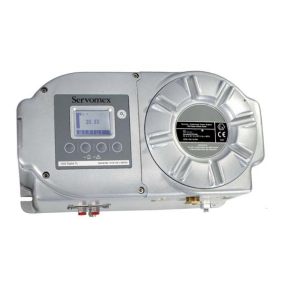
1900 Digital O Gas Analyser Construction ® The analyser comprises an aluminium enclosure, with Viton /silicone rubber seals. Refer to Figure 1. The analyser has two internal compartments: • Sample/control compartment This compartment (shown in Figure 3, page 5) contains intrinsically safe components such as the sample measurement transducer and the heater. - Page 11 1900 Digital O Gas Analyser Description Description Hinged cover Certification label Display Soft key 4 Sample gas label Soft key 3 Locking screws (4 off) Fault LED (red) Locking screw * Soft key 2 † Identification/rating label Alarm LED (yellow) Threaded cover Soft key 1 * The locking screw may be in a different orientation with respect to the cover (6),...
- Page 12 1900 Digital O Gas Analyser Description Description Cable entry holes (3 off) Inlet/outlet bulkhead Earth (ground) terminal Sample gas outlet Sample gas inlet M4 screws (8 off) Breather vent Figure 2 - Base of the analyser 01910001A / Revision 1...
- Page 13 1900 Digital O Gas Analyser With Viton pipelines and standard inlet/outlet ‘T’ piece With stainless steel pipelines and optional high flow bypass ‘T’ piece Replacing the optional inlet filter Description Description Transducer Stainless steel pipelines Pipe connector nuts (2 off) ‘T’...
- Page 14 1900 Digital O Gas Analyser Description Earth (ground) connection Fault relay (relay 3) Range change relay (relay 4) Electrical supply connection terminals Fuse F101 Relay terminals Alarm 1 relay (relay 1) Alarm 2 relay (relay 2) milliAmp output terminals Figure 4 - Power/signal compartment 01910001A / Revision 1...
-
Page 15: Specification
1900 Digital O Gas Analyser SPECIFICATION WARNING You must install and use the analyser in accordance with the requirements of this section and subsequent sections of the manual. If you do not, people may be injured, the protection facilities incorporated into the design of the analyser may not operate as intended, sample gas measurements may not be accurate, or the analyser may be damaged. -
Page 16: Calibration Gases
1900 Digital O Gas Analyser Calibration gases The calibration gases must be clean, non-corrosive, free from oil/ condensates and compatible with the materials listed in Appendix A3. Low calibration gas Clean, dry nitrogen, 99.9% pure High calibration gas Clean gas supply with nominal ’atmospheric’ oxygen concentration (20.95%). -
Page 17: Electrical Data
1900 Digital O Gas Analyser Electrical data Electrical supply Voltage 100 to 120 V a.c. or 220 to 240 V a.c. * Frequency 50 to 60 Hz Maximum power consumption 50 VA Internal fuse rating 100 to 120 V supply T 2.0 A H 250 V 220 to 240 V supply T 1.0 A H 250 V... -
Page 18: Performance
1900 Digital O Gas Analyser Performance The display indications given below are the default indications. You can configure the analyser to provide other display indications (see Section 6.3). Display indication Measured volume % oxygen Targeted measurement range 0 to 21% oxygen Linearity <... -
Page 19: Hazardous Area Certification
1900 Digital O Gas Analyser Hazardous area certification When correctly installed as described in this manual, the analyser is certified to operate in the following hazardous areas (as specified by the certification label fitted to the analyser, see Figure 5): •... - Page 20 1900 Digital O Gas Analyser • North America The analyser is CSA approved for use in USA and Canada in the following locations: C ≤ Ta ≤ +50 Class I, Division 1, Groups A, B, C, D T4 (-10 C ≤ Ta ≤ +50 Class I, Zone 1, Ex ia d IIC T4 (-10 C ≤...
-
Page 21: Unpack The Analyser
(see Figure 2). Inspect the analyser and the other items supplied, and check that they are not damaged. If any item is damaged, immediately contact Servomex or your local Servomex agent. Check that you have received all of the items that you ordered. If any item is missing, immediately contact Servomex or your local Servomex agent. -
Page 22: Analyser User Interface
When you first switch on the analyser, a ’start-up screen’ is displayed while the analyser carries out a self-test. The start-up screen shows the Servomex name, the message "System Check" and a ‘self-test time elapsed/remaining’ indicator, identifying the progress of the tasks being... -
Page 23: Soft Key Legends
1900 Digital O Gas Analyser The Measurement screen is then displayed, as shown in Figure 7 below. Gas being measured Measurement units Transducer number Current measurement ("1" always shown) Fault icon: see Section 8 Status icon bar Alarm icon: see (see Section 4.4) Section 6.4.1 Software health... -
Page 24: Status Icon Bar
1900 Digital O Gas Analyser Other soft key legends which are used on the various screens are as follows: Legend Meaning Function (when soft key pressed) Back Cancels the current screen and displays the previous screen in the menu structure. Accept Accepts the currently selected option or data. -
Page 25: Menu Options/Screens And Password Protection
1900 Digital O Gas Analyser Menu options/screens and password protection The menu structure of the analyser is shown in Figure 8, which indicates that some of the options/screens are password protected. When an option/screen is password protected, this means that the correct corresponding password has to be entered before the option/screen can be accessed. - Page 26 1900 Digital O Gas Analyser NOTES: (Start-up screen) Specifies the corresponding section in [X.Y.Z] [4.2] this manual. Specifies that the option/screen is always protected by the supervisor password. Specifies that the option/screen can be (Measurement screen) [4.2] protected by the supervisor password. Specifies that the option/screen can be protected by the operator password.
-
Page 27: The Menu Screen
1900 Digital O Gas Analyser The Menu screen Some of the menu screens referenced below may not be available: refer to the note at the start of Section 4. The Menu screen (see Figure 9) provides access to other screens in the menu structure, and is displayed by pressing the soft key when the Measurement screen is displayed. -
Page 28: The Settings Screen
Settings screen again, or press and hold the soft key to show the Measurement screen again. You may be asked to provide the information from this screen to the Servomex support team; for example, as an aid to fault diagnosis. 01910001A / Revision 1... -
Page 29: Editing On-Screen Data
1900 Digital O Gas Analyser 4.10 Editing on-screen data A common method is used for editing data shown on all of the different screens. When you press the soft key to edit an item of data, the screen changes to show the corresponding edit screen, with the first digit highlighted;... -
Page 30: Installation And Set-Up
1900 Digital O Gas Analyser INSTALLATION AND SET-UP WARNING You must not modify the analyser in any way (either mechanically or electrically). If you do, the certification of the analyser will be invalidated, and it may not operate safely. WARNING The analyser must be installed by a suitable skilled and competent technician or engineer. - Page 31 1900 Digital O Gas Analyser Description Fixing lugs (4 off) Figure 13 - Fixing dimensions (mm) 01910001A / Revision 1...
-
Page 32: Remove The Power/Interface Compartment Cover
1900 Digital O Gas Analyser Remove the power/interface compartment cover WARNING The power/interface compartment cover is heavy. Ensure that you do not drop the cover once it is disengaged from the body of the analyser. If you do, you may injure yourself or damage other equipment. CAUTION Place the cover carefully on a clean surface, resting on the exterior of the cover, so that the pregreased threads do not become contaminated. -
Page 33: Configure The Cable Entry Hole(S)
1900 Digital O Gas Analyser • The volt-free relay contacts are isolated from the analyser mains circuits and from each other, so that either mains voltage circuits or signal voltage circuits can be connected to the contacts. • The milliAmp output and (where enabled) RS485 terminals are separated from the analyser mains circuits by reinforced insulation. -
Page 34: Interface Signal Connections
1900 Digital O Gas Analyser 5.3.3 Interface signal connections WARNING All of the analyser interface signal outputs are considered to be incendive and therefore must only be connected to safe area equipment. CAUTION To comply with EMC requirements, you must use screened 4 to 20 mA cables to connect to the milliAmp outputs. -
Page 35: Mains Electrical Supply Connection
1900 Digital O Gas Analyser 5.3.4 Mains electrical supply connection CAUTION Ensure that the analyser as supplied is correctly configured for your mains electrical supply voltage. If the analyser is not correctly configured for your mains electrical supply voltage, the analyser may not operate correctly, or it may be damaged when you operate it. -
Page 36: Refit The Power/Interface Compartment Cover
1900 Digital O Gas Analyser Refit the power/interface compartment cover WARNING The power/interface compartment cover is heavy. Ensure that you do not drop the cover when you refit it to the body of the analyser. If you do, you may injure yourself or damage other equipment. CAUTION Ensure that the pregreased threads of the cover do not become contaminated. -
Page 37: Connect The Sample/Calibration Gas Pipe(S)
1900 Digital O Gas Analyser Connect the sample/calibration gas pipe(s) WARNING Ensure that the pipes that you connect to the analyser are routed so that they do not present a trip hazard to people. WARNING Sample and calibration gases may be toxic, asphyxiant or flammable. Ensure that the external connections are leak free at full operating pressure before you use sample or calibration gases. -
Page 38: Switch On/Set-Up
1900 Digital O Gas Analyser Switch on/set-up When the electrical supply to the analyser is switched on, the Alarm LED and the Fault LED will both go on for 1 second to demonstrate that they are functioning correctly, and will then go off again. When you switch on the electrical supply to the analyser, a ’start-up screen’... - Page 39 1900 Digital O Gas Analyser Selecting the security level As supplied, the security level is set to ‘high’, the supervisor password is set to "2000" and the operator password is set to "1000". We recommend that you select your required security level and change the password(s) as described below to provide additional protection.
- Page 40 If you change a password, ensure that you record the new password somewhere safe. Otherwise, if you cannot recall the new password, you will have to contact Servomex or your local Servomex agent for assistance. Use the following procedure to change the supervisor and operator passwords:...
-
Page 41: Setting The Clock
1900 Digital O Gas Analyser 5.7.2 Setting the clock Use the following procedure to set the date and time: Press the soft key to display the Menu screen, use the soft keys to highlight the "Settings" menu option, then press the soft key. -
Page 42: Changing Regional Settings
1900 Digital O Gas Analyser 5.7.3 Changing regional settings You can configure the following analyser regional settings so that the information shown on the various screens is better suited to your local conventions: Setting Options available Language Various languages are supported. Date format Day/Month/Year * or Month/Day/Year. -
Page 43: General Operation
1900 Digital O Gas Analyser GENERAL OPERATION CAUTION Sample and calibration gases must be as specified in Sections 2.2 and 2.3. If the gas pressures and/or flow rates are above those specified in Sections 2.2 and 2.3, you must regulate the gases externally, before they enter the analyser. CAUTION You must leave the analyser (with the electrical supply switched on) for at least 4 hours before you allow sample or calibration gases into the analyser. -
Page 44: Taking Sample Readings
1900 Digital O Gas Analyser Use the soft keys to select the required calibration, that is: • ’Lo’ (low calibration gas). • ’Hi’ (high calibration gas) Press the soft key. The Calibrate target value screen will then be shown (see Figure 21), identifying the target value and the current reading. -
Page 45: Selecting Display Units
1900 Digital O Gas Analyser Selecting display units You can change the measurement units shown on the display. The following display units are supported: Units Meaning volume % parts per million volume parts per million mg/m3 mg m (milligrams per normal cubic metre) mol/mol mols per mol (or moles per mole) % LEL... - Page 46 1900 Digital O Gas Analyser Use the soft keys to highlight the "Unit selection" menu option, then press the soft key. The Currently selected units screen will then be displayed, as shown in Figure 23. Figure 23 - The Currently selected units screen If you want to view or change the units conversion factor, continue at Step 6.
-
Page 47: Configuring The Measurement Alarms
1900 Digital O Gas Analyser Configuring the measurement alarms 6.4.1 Alarm modes and levels Two separate measurement alarms are available, and you can configure each alarm to operate in one of three modes: Alarm mode Operation None The alarm is not used (that is, an alarm condition will not be activated under any circumstances). -
Page 48: Hysteresis Levels
1900 Digital O Gas Analyser 6.4.3 Hysteresis levels The hysteresis level associated with a measurement alarm determines when an alarm condition (once activated) is deactivated, and this depends on the alarm mode, as follows: Alarm mode Effect of hysteresis Low alarm Once the low alarm condition has been activated, the alarm condition will not be deactivated until a sample measurement is above (alarm level + hysteresis level). -
Page 49: Setting The Measurement Alarm Levels And Modes
1900 Digital O Gas Analyser 6.4.4 Setting the measurement alarm levels and modes Ensure that the measurement alarm and hysteresis levels are not too close to the expected sample measurements. (If they are, minor - and acceptable - variations in your sample gas concentrations will result in spurious alarms.) ... -
Page 50: Unlatching Measurement Alarms
1900 Digital O Gas Analyser 6.4.5 Unlatching measurement alarms When necessary, use the following procedure to unlatch any ‘latched’ measurement alarm(s) (see Section 6.4.2): On the Measurement screen, press the soft key; the Alarm option screen (Figure 26) will then be displayed. With the "Unlatch"... -
Page 51: Configuring And Using The Milliamp Output
1900 Digital O Gas Analyser Configuring and using the milliAmp output 6.5.1 Overview The analyser is supplied with a milliAmp output facility. The milliAmp output provides a constantly updated output (through a signal cable connected to the analyser), in which the current represents the value of gas sample measurements. The analyser allows you to specify two separate output configurations for the milliAmp outputs: Range 1 and Range 2. -
Page 52: Introduction To The Milliamp Output Parameters
1900 Digital O Gas Analyser 6.5.2 Introduction to the milliAmp output parameters The milliAmp output parameters that you must set up are as follows: Parameter Values/options Range 1 high level The Range 1 highest sample measurement (span) *. Range 2 high level The Range 2 highest sample measurement (span) *. -
Page 53: Setting Up The Milliamp Output Parameters
1900 Digital O Gas Analyser 6.5.3 Setting up the milliAmp output parameters Use the following procedure to set up the milliAmp output parameters: Press the soft key to display the Menu screen, use the soft keys to highlight the "Set up" menu option, then press the soft key. -
Page 54: Selecting The Range Associated With A Measurement
1900 Digital O Gas Analyser 6.5.4 Selecting the Range associated with a measurement Use the following procedure at any time during sampling to change the Range (see Section 6.5.1) associated with a gas measurement: Press the soft key to display the Menu screen, use the soft keys to highlight the "Set up"... -
Page 55: Calibrating The Milliamp Output
1900 Digital O Gas Analyser 6.5.5 Calibrating the milliAmp output Use the following procedure to calibrate the milliAmp output: Press the soft key to display the Menu screen. Use the soft keys to highlight the "Service" menu option, then press the soft key. -
Page 56: Checking The Milliamp Output
1900 Digital O Gas Analyser 6.5.6 Checking the milliAmp output If required, use the following procedure at any time to perform a check on a milliAmp output: Press the soft key to display the Menu screen, use the soft keys to highlight the "Service" menu option, then press the soft key. -
Page 57: Checking The Relay Signal Outputs
1900 Digital O Gas Analyser Checking the relay signal outputs If required, use the following procedure at any time to perform a check on the four signal output relays: Press the soft key to display the Menu screen, use the soft keys to highlight the "Service"... -
Page 58: Adjusting The Display
1900 Digital O Gas Analyser Adjusting the display At any time, you can adjust the screen display to suit the ambient light conditions, as described in Sections 6.7.1 and 6.7.2. 6.7.1 Adjusting the backlight timer When the analyser is first switched on, the backlight goes on to illuminate the screen. If no soft key is pressed, the backlight will remain on for the preset ‘backlight time’, and will then go off. -
Page 59: Adjusting The Contrast
1900 Digital O Gas Analyser 6.7.2 Adjusting the contrast On the Settings screen, highlight the "Contrast" option, then press the soft key. The Contrast screen will then be displayed, as shown in Figure 40. Figure 40 - The Contrast screen Use the soft keys to increase or decrease the contrast to the required level, then press the... -
Page 60: Routine Maintenance
1900 Digital O Gas Analyser ROUTINE MAINTENANCE WARNING The analyser must be maintained by a suitable skilled and competent technician or engineer. WARNING Sample and calibration gases may be toxic, asphyxiant or flammable. Never inspect the inlet filter, open the front cover of the sample/control compartment, or service or repair the analyser while such gases are still connected to it. -
Page 61: Replacing The Inlet Filter
1900 Digital O Gas Analyser Replacing the inlet filter WARNING Do not open the hinged door of the sample/control compartment if an explosive atmosphere may be present. New inlet filters and ‘O’ rings are available as spares: see Section 10. On an analyser with a solvent-resistant transducer, ensure that you fit the correct type of inlet filter ‘O’... -
Page 62: Inspecting/Replacing The Fuse (When Necessary)
1900 Digital O Gas Analyser Inspecting/replacing the fuse (when necessary) 7.3.1 Removing the cover and replacing the fuse WARNING Ensure that the electrical supply is isolated/locked out from the analyser. If you do not, there will be a danger of injury or death from electric shock. WARNING Do not remove the cover of the power/signal compartment if an explosive atmosphere may be present. -
Page 63: Refitting The Cover
If a new fuse fails immediately after you have fitted it, there may be an electrical fault in the analyser: contact Servomex or your Servomex agent. 01910001A / Revision 1... -
Page 64: Use Of The Analyser With Toxic Gases
We recommend that you leak-test the analyser at least once every 6 months: • If there are leaks within the analyser, it must be returned to Servomex for repair. Do not continue to use the analyser. -
Page 65: Preventative Maintenance
Note that you will always be informed in advance if any repairs or new parts are required for your analyser. Contact Servomex or your local Servomex agent to arrange for a preventative maintenance contract. 01910001A / Revision 1... -
Page 66: Fault Finding
Fault message Recommended actions Calibration fault Recalibrate (both low and high) as described in Section 6.1. If the fault persists, contact Servomex or your local Servomex agent for assistance. Code fault Contact Servomex or your local Servomex agent for assistance. - Page 67 Ensure that the electrical cabling connected to the analyser is not open circuit. Turn the analyser off, and then turn it on again. If the fault persists, contact Servomex or your local Servomex agent for assistance. mA not detected Contact Servomex or your local Servomex agent for assistance.
-
Page 68: Viewing Fault Messages
For general analyser fault finding, refer to the table on the following pages. If you have read through the table and still cannot rectify a fault, or cannot identify the cause of a fault, contact Servomex or your local Servomex agent for assistance. 01910001A / Revision 1... - Page 69 • Switch off the analyser, then switch it on again. • If the fault persists, contact Servomex or your local Servomex agent for assistance. The software health indicator is not Carry out the recommended actions for the "The...
- Page 70 1900 Digital O Gas Analyser Fault symptom Recommended actions analyser measurements are not as Check that the correct display units have been expected. selected, and that the units conversion factor has been correctly entered (see Section 6.3). analyser measurements are Check that the sample gas supply pressure is unstable.
- Page 71 If you have configured the milliAmp output to jam high or jam low, check whether a fault condition exists (see Section 6.5.2). Otherwise, contact Servomex or your local Servomex agent for assistance. The milliAmp output is not as Ensure that the electrical cabling connected to the expected.
-
Page 72: Storage And Disposal
The analyser is not suitable for disposal in municipal waste streams (such as landfill sites, domestic recycling centres and so on): refer to Appendix A4. If you send the analyser to Servomex or your local Servomex agent for disposal, it must be accompanied by a correctly completed decontamination certificate. -
Page 73: Spares
The standard spares available for the analyser are shown below. You can order these spares from Servomex or your Servomex agent. Spare Part Number Inlet filter: 20 μm, stainless steel... -
Page 74: A1 Display Unit Conversion Factors
1900 Digital O Gas Analyser APPENDIX DISPLAY UNIT CONVERSION FACTORS When you select display units as described in Section 6.3, you must ensure that you also enter the correct units conversion factor, as shown in the table below: To convert use the units applicable †... -
Page 75: A2 Panel Mounting The Analyser
Inspect the components supplied, and check that they are not damaged. If any item is damaged, immediately contact Servomex or your local Servomex agent. Check that you have received all of the items listed below. If any item is missing from the kit, immediately contact Servomex or your local Servomex agent. - Page 76 1900 Digital O Gas Analyser Figure A1 - Panel mounting arrangement/dimensions (mm): sheet 1 of 2 01910001A / Revision 1...
- Page 77 1900 Digital O Gas Analyser Plan view, showing analyser and mounting assembly Front view, showing cutout and fixing dimensions Side view, showing optional additional support Description Description M8 x 35 hex head bolt M8 x 20 cap head screw M8 washer analyser mounting position †...
-
Page 78: Materials In Contact With Sample And Calibration
1900 Digital O Gas Analyser APPENDIX MATERIALS IN CONTACT WITH SAMPLE AND CALIBRATION GASES The materials of the parts of the analyser in contact with the sample and calibration gases are listed below. These materials have a wide range of chemical compatibility and corrosion resistance. -
Page 79: Product Disposal/Applicability Of The Waste
Tel: (44) 1892 652181 Fax: (44) 1892 662253 Global email: info@servomex.com If you send the analyser to Servomex or your local Servomex agent for disposal, it must be accompanied by a correctly completed decontamination certificate. 01910001A / Revision 1... - Page 80 1900 Digital O Gas Analyser This page intentionally blank. 01910001A / Revision 1...
-
Page 81: A5 Compliance And Standards Information
• The analyser has been assessed to IEC 61010-1:2001 (+Corr 1: 2002 + Corr 2:2003) for electrical safety, rated in accordance to IEC 60664-3 Category II, Pollution Degree 2. • Servomex Group Ltd is a BS EN ISO 9001 and BS EN ISO 14001 certified organisation. 01910001A / Revision 1... -
Page 82: A6 Atex Certificates
1900 Digital O Gas Analyser APPENDIX ATEX CERTIFICATES The ATEX certificates for the analyser are shown on the following pages. 01910001A / Revision 1... - Page 83 1900 Digital O Gas Analyser 01910001A / Revision 1...
- Page 84 1900 Digital O Gas Analyser 01910001A / Revision 1...
- Page 85 1900 Digital O Gas Analyser 01910001A / Revision 1...
- Page 86 1900 Digital O Gas Analyser 01910001A / Revision 1...
- Page 87 1900 Digital O Gas Analyser 01910001A / Revision 1...
- Page 88 1900 Digital O Gas Analyser 01910001A / Revision 1...
- Page 89 1900 Digital O Gas Analyser 01910001A / Revision 1...
- Page 90 1900 Digital O Gas Analyser 01910001A / Revision 1...
Need help?
Do you have a question about the SERVOTOUGH 1900 Digital and is the answer not in the manual?
Questions and answers