Servomex SERVOTOUGH Fluegas 2700 Installation Manual
Combustion gas analysers
Hide thumbs
Also See for SERVOTOUGH Fluegas 2700:
- Quick start manual (41 pages) ,
- Installation manual (117 pages)

Related Manuals for Servomex SERVOTOUGH Fluegas 2700


Summary of Contents for Servomex SERVOTOUGH Fluegas 2700
- Page 1 SERVOTOUGH Fluegas (2700) Combustion Gas Analyser Installation Manual Part Number: 02700005B Revision: Language: UK English...
- Page 2 This page intentionally blank...
-
Page 3: Table Of Contents
SERVOMEX 2700 OVERVIEW ........ - Page 4 Servomex 2700 sensor head and control unit overview ....7 Figure 2 Servomex 2700 sensor head dimensions (typical) ....11 Figure 3 Adaptor flange installation .
-
Page 5: Introduction
Alert the user to pertinent facts and conditions CAUTION – refer to the Installation Manual Scope of this manual This manual covers the installation of the Servomex 2700 Combustion Gas Analyser and the various options that are available. • Refer to the QuickStart Manual or Technical Data Sheet for latest technical specification. - Page 6 CE Marking The Servomex 2700 analyser carries the CE mark which indicates conformity with the European Community Directives on CE Marking (93/68/EEC), Electromagnetic Compatibility (EMC 89/336/EEC) and Low Voltage Directive (LVD 73/23/EEC). Servomex 2700 control units are marked in conformity with the Explosive Atmospheres (ATEX) Directive (94/9/EC) when fitted with a European hazardous area certification marking plate.
-
Page 7: General Safety Information
Flammable gases must not be used for the aspirator supply. • The Servomex 2700 sensor head is not suitable for use in hazardous areas / locations without the use of appropriate safety purge equipment. • Servomex 2700 EU2/UK2/FM2/CS2 approved control units must be used if the installation is in a Category 3/Zone 2/Division 2 hazardous area/location. -
Page 8: Hazardous Area Approval And Certification
(part number 02700008B) which is supplied with each hazardous area certified unit. In summary, the Servomex 2710 control unit is certified for use in Category 3/Zone 2/ Division 2 areas (for both gas and dust hazards) and is available with the following... -
Page 9: Unpacking
Unpacking WARNING The Servomex 2700 sensor head and control unit weigh approximately 17Kg (38lbs) and 10Kg (22lbs) respectively and care must be taken when handling. • Remove the Servomex 2700 components from their packing and inspect for obvious external damage. - Page 10 This page is intentionally blank Servomex 2700 Installation Manual...
-
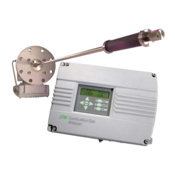
Page 11: Servomex 2700 Overview
SERVOMEX 2700 OVERVIEW Overview Figure 1 Servomex 2700 sensor head and control unit overview Control Unit Sensor Head Key to Figure 1 – Servomex 2700 sensor head and control unit overview Terminal enclosure cover Sample probe Sensor head cover Sample probe filter 4"... -
Page 12: Sensor Head Description
The Servomex 2700 Combustion Gas Analyser measures combustion and similar gases to provide an analysis of the oxygen concentration and/or the level of unburned combustibles. The analyser comprises two separate units which may be mounted up to 300m (975ft) apart for oxygen only and 100m (325ft) apart whenever the combustibles measurement option is fitted. -
Page 13: Installation Of Sensor Head And Probe Tube
Refer to Figure 2. NOTE All Servomex adaptor flanges, interface flanges, probe support tubes, stand-offs and thermal spacers, including the integral flange on the sensor head, are suitable for fitting onto the standard flanges (raised face [<1.6mm] or flat faced). But, they do not comply with any national or international standards and the analyser’s... -
Page 14: Table 1 Sensor Head Operating Environment
The covers may be removed during installation or servicing only if there is negligible risk of pollution or contamination of the electronic circuits contained within the enclosures and if the covers are securely replaced immediately after the operation is completed. Refer to Section 6. Servomex 2700 Installation Manual... -
Page 15: Figure 2 Servomex 2700 Sensor Head Dimensions (Typical)
143mm 123mm 131mm 188mm 138mm Key to Figure 2 – Servomex 2700 sensor head dimensions Analyser mounting flange 4" Sample vent port 1/8" NPT (INT) Sample probe connection 1/2" NPT (INT) Calibration gas inlet 1/4" OD compression fitting Purge gas exit, 1/4" NPT (INT), or breather fitting Combustion sensor auxiliary air supply 1/4"... -
Page 16: Flange Mounting Arrangements
M16x65mm or 5/8"x2½" bolts will be required. The sensor head will be provided with sufficient gaskets, M16 studding and M16 nuts and washers to mount the sensor head configuration supplied onto a Servomex weld on 4" flange. -
Page 17: Weld-On Flange Installation
M16 nuts and washers [6]. Table 2 – Sensor head adaptor flange kits Mating Pattern Servomex Kit No. Mtg.hole Mates With 02750992 10.8 dia 120.6 Servomex Model 700B /N 02750991 152.4 3" ANSI 150 02750991 145.0 DIN 65 PN16 02750991 145.0 JIS 80 5Kg/cm 02750990 130.0... -
Page 18: Adaptor Flange Installation
4" flange on 2700 sensor head M16 nuts and washers (4 off each) M16 by 55mm studs (4 off) Studs (type and length specific to flue mounting flange) Nuts and washers (number and size to suit flue mounting flange) Servomex 2700 Installation Manual... -
Page 19: High Temperature Stand-Off Installation
M16 nuts and washers [6]. • If a probe retention flange is to be installed then screw the M16x80mm studs supplied into the threaded holes in the stand-off flange and install the probe retention flange as described in Section 3.2.6. Servomex 2700 Installation Manual... -
Page 20: Figure 4 High Temperature Stand-Off Flange Installation
High temperature stand-off ANSI 4" gasket 4" flange on 2700 sensor head M16 nuts and washers (4 off each) M16 by 55mm studs (4 off) M16 nuts and washers (4 off) M16 by 55mm studs (4 off) Servomex 2700 Installation Manual... -
Page 21: Thermal Spacer Installation
• If a probe retention flange is to be installed then replace the M16x80mm studs with the M16x105mm studs supplied. Install the probe retention flange as described in Section 3.2.6. Servomex 2700 Installation Manual... -
Page 22: Figure 5 Thermal Spacer Installation
Mounting flange on flue. Adaptor flange fitted where necessary to provide 4" ANSI 150lb flange ANSI 4" gasket Insulation flange 4" flange on Servomex 2700 sensor head M16 nuts and washers (4 off each) ANSI 4" gasket M16 by 80mm studs (4 off) -
Page 23: Probe Retention Flange Installation
4" ANSI sealing gasket [7] and the four M16 nuts and washers [8] provided. Ensure that the vent hole in the gasket and in the retention flange are aligned with the sample vent on the sensor head. Servomex 2700 Installation Manual... -
Page 24: Figure 6 Probe Retention Flange Installation
Key to Figure 6 – Probe retention flange installation Adaptor flange 4 x M16x80mm studs Ceramic probe 4" sealing gasket (large central hole) Probe retention flange 4 x M16 half nuts and washers 4" ANSI sealing gasket 4 x M16 nuts and washers Servomex 2700 Installation Manual... -
Page 25: Sample Probe Installation
(using PTFE tape to seal the thread) or to a probe retention flange. The probe retention flange is used to avoid potential damage to the fragile probe when removing the sensor head from the flue for maintenance purposes. Refer to Section 3.2.6 for probe retention flange installation. Servomex 2700 Installation Manual... -
Page 26: Table 3 Sample Probe Part Numbers
Open-ended, High temperature alloy, <700°C S2740704A S2740704B S2740704C S2740704D Filtered, Stainless Steel, <700°C S2740702A S2740702B S2740702C Filtered, High temperature alloy, <1000°C S2740705A S2740705B Supported filtered, Stainless Steel, <700°C S2740703C S2740703D S2740703E S2740703F Open-ended ceramic, <1750°C 02740707A 02740707B 02740707C Servomex 2700 Installation Manual... -
Page 27: Figure 7 Sample Probe And Filter Construction
Sample probe and filter construction Key to Figure 7 – Sample probe and filter construction Fibre sealing washer Fibre sealing washer ½" NPT threaded mounting hole in Servomex 2700 filter block 2700 mounting flange Mounting flange on flue ½" compression to ½" NPT adaptor... -
Page 28: Figure 8 Supported Probe Construction
Sample filter shroud M8x18mm fixing screw Sample filter shroud collar Sample probe retaining disc Sample probe retaining disc M5x10mm fixing screws (2 x) Support tube 4" sealing gasket Support tube flange 4 x M16 nuts and washers Sample probe tube Servomex 2700 Installation Manual... -
Page 29: Supported Probe Installation
Fit the probe tube into the coupling until the probe tube bottoms out in the sensor head. Swage the coupling ferrule onto the tube by tightening the coupling finger tight plus a further 3/4 to 1 turn. Release the union nut from the fitting in the sensor head. Servomex 2700 Installation Manual... - Page 30 Attach the sensor head to the protruding length of the sample probe tube using the compression fitting. Attach the sensor head to the support tube flange and secure in place with the four M16 nuts and washers [8]. Servomex 2700 Installation Manual...
-
Page 31: Figure 9 Probe Support Tube Installation
Mounting flange on flue. Adaptor flange fitted where necessary to provide 4" ANSI 150 lb flange. ANSI 4" gasket Support tube flange 4" flange on 2700 sensor head M16 nuts and washers (4 off each) ANSI 4" gasket M16 by 80mm studs Servomex 2700 Installation Manual... -
Page 32: Calibration And Utilities Supplies
Calibration and utilities supplies Refer to Figure 2. WARNING The maximum pressure that should be applied to any of the Servomex 2700 analyser inlet ports is 1 bar (max). A number of calibration and utilities gas supplies are required by the sensor head depending on the sensor configuration used. -
Page 33: Electrical Installation
"F 6.3A HRC" in each supply conductor. The disconnect device (see also Section 1.3) must disconnect each supply conductor. The fuses must be marked as being associated with this equipment. Ensure that the installation conforms to the relevant national and local safety requirements. Servomex 2700 Installation Manual... -
Page 34: Table 4 Sensor Head Electrical Power Connections
Table 4 – Sensor head electrical power connections Terminal Electrical power Live TB1-L 100-120Vac or 220-240Vac Neutral TB1-N 50/60Hz, 600VA maximum Protective earth TB1-Protective ground Note that terminal TB1-protective ground is at the right-hand side Servomex 2700 Installation Manual... -
Page 35: Figure 10 Sensor Head Terminal Enclosure Detail
Terminal block TB3 (oxygen and sensor head temperature wiring) Pin 1 at right-hand side Fuse F1 Terminal block TB1 (main power wiring) Plastic safety cover Terminal block TB9 (mains voltage selection) Pin 1 at right-hand side Servomex 2700 Installation Manual... - Page 36 This page is intentionally blank Servomex 2700 Installation Manual...
-
Page 37: Installation Of Control Unit
M8 by 20mm screws and washers. Four 12mm diameter holes are provided for mounting the control unit to the wall. Servomex recommend the use of M8 or 3/8" bolts to fix the control unit to the wall. -
Page 38: Table 5 Control Unit Operating Environment
The covers may be removed during installation or servicing only if there is negligible risk of pollution or contamination of the electronic circuits contained within the enclosures and if the covers are securely replaced immediately after the operation is completed. Refer to Section 6. Servomex 2700 Installation Manual... -
Page 39: Figure 11 Control Unit Installation
3/4" NPT (INT) threaded cable conduit entries or optional adaptors as required Enclosure breather fitting (optional) or blanking port Wall mounting brackets (optional) EMC earth terminal 1/4" NPT (INT) threaded enclosure purge inlet and outlet fittings (optional) or blanking plugs Servomex 2700 Installation Manual... -
Page 40: Electrical Installation
• The Servomex 2700 is rated in accordance with IEC 644 for INSTALLATION CATEGORY II which is characterised as being local level (not distribution level), appliances and portable equipment with over-voltage impulse withstand up to 2500V. -
Page 41: Table 6 Control Unit Electrical Power Voltage Selection
All electrical connections and access to the mains power fuse, F1, are made to the control PCB inside of the control unit enclosure. After electrical connections are complete ensure that the safety cover is re-fitted and the access door is fully bolted down. Servomex 2700 Installation Manual... -
Page 42: Figure 12 Control Unit Enclosure Detail
Terminal block TB2 interconnection wiring and external signal connections Terminal block TB1 interconnection wiring M4 cable screen termination studs (4 studs) Keypad ribbon cable connection PL2 LCD viewing angle adjustment RV2 LCD ribbon cable connection PL1 Servomex 2700 Installation Manual... -
Page 43: Enclosure Purge Connection
If a purge facility is fitted as a means of hazardous area protection, ensure that the purge flows and pressures etc., are as specified by the purge system manufacturer. Servomex 2700 Installation Manual... -
Page 44: Table 7 Control Unit Electrical Power Connections
Note that TB4-12 is at the top The relay outputs may be configured by the user to be either concentration alarms, fault indications, autocalibration or blowback valve drives via the analyser software interface. Minimum 10mA 5V AC or DC. Maximum 3A/250Vac 1A/28Vdc. Servomex 2700 Installation Manual... -
Page 45: Table 9 Analogue Output Connections
The remote dry contacts must be suitable for use with the low voltage signal generated by the control unit, i.e. 5V 50µA maximum. Calibration and blowback parameters to be set by the user via the software interface prior to remote function initiation. Servomex 2700 Installation Manual... - Page 46 This page is intentionally blank Servomex 2700 Installation Manual...
-
Page 47: Initial Startup Procedure
Calibration gas 1000ppm(v) CO balance air ** COe 'HIGH CAL' 0-10 ±0.020 ** calibration gas composition can be between 500ppm(v) to 1,000ppm(v) for a 1750702 sensor and 1,000ppm(v) to 2,000ppm(v) in air for a 1750703 sensor. Servomex 2700 Installation Manual... -
Page 48: Visual Inspection
The solenoid valve will operate after a time interval of between 15 and 60 minutes depending on configuration and ambient temperature. Servomex 2700 Installation Manual... -
Page 49: Analogue Output Span Setup
Check that the combustibles sensor temperature is stable at 300° ±10°C. Analogue output span setup Refer to the Servomex 2700 QuickStart manual [02700003B]. • If a zirconia sensor is fitted then select the SET OUTPUTS option in the SERVICE menu and select 20mA for the oxygen analogue output. -
Page 50: Sensor Calibration
Sensor calibration With the sensor head power on and at stable temperature for a minimum of 24 hours refer to the Servomex 2700 QuickStart manual. • With an air sample applied to the calibration gas inlet at 600 ±20ml/min flow rate perform a HIGH point calibration of the zirconia sensor (if fitted) and a LOW point calibration of the combustibles sensor (if fitted). -
Page 51: Maintenance And Servicing
Analysers flow rates, air supplies, probes and filters (internal an external), should be checked once per year, as well as the whole analyser and cabling for signs of wear. In more rugged applications, these times may need to be shorter, depending on experience. Servomex 2700 Installation Manual... - Page 52 This page is intentionally blank Servomex 2700 Installation Manual...
-
Page 53: Interconnecting Wiring Schedules
Maximum heater loop resistance 4 ohms. Note: For optional sensor head temperature display and the sensor head temperature high and sensor head temperature low faults at control unit, add 1 extra twisted pair to cable specification. Servomex 2700 Installation Manual... -
Page 54: Oxygen Sensor Only Interconnection Wiring Schematic
Figure 13 Oxygen sensor only interconnection wiring schematic Servomex 2700 Installation Manual... -
Page 55: Table 13 Oxygen Sensor Only Interconnecting Wiring
TB3-4 TB1-8 TB3-5 Zirconia sensor heater supply (polarity not important) TB2-7 TB3-6 TB2-8 TB3-7 Zirconia sensor temperature output TB2-9 TB3-8 TB2-10 TB3-9 Overall cable screen connection * Enclosure * for correct earthing details see Section 4.2 Servomex 2700 Installation Manual... -
Page 56: Combustibles Only Interconnection Wiring Schematic
Figure 14 Combustibles only interconnection wiring schematic Servomex 2700 Installation Manual... -
Page 57: Table 14 Combustibles Only Interconnecting Wiring
Combustibles sensor bridge offset TB1-4 correction TB5-11 TB1-5 TB5-12 Combustibles sensor temperature output ground TB2-6 Stud Individual screens and unused cores terminal 'S’ Enclosure TB5-13 Overall cable screen connection * Enclosure * for correct earthing details see Section 4.2 Servomex 2700 Installation Manual... -
Page 58: Figure 15
Figure 15 Dual sensor interconnection wiring schematic Servomex 2700 Installation Manual... -
Page 59: Table 15 Dual Sensor Interconnecting Wiring
TB3-5 Zirconia sensor heater supply (polarity not important) TB2-7 TB3-6 TB2-8 TB3-7 Zirconia sensor temperature output TB2-9 TB3-8 TB2-10 Stud Individual screens and unused cores terminal 'S’ Enclosure * for correct earthing details see Section 4.2 Servomex 2700 Installation Manual... - Page 60 NOTES Servomex 2700 Installation Manual...
Need help?
Do you have a question about the SERVOTOUGH Fluegas 2700 and is the answer not in the manual?
Questions and answers