
Related Manuals for Servomex SERVOTOUGH LaserSPII mini


Summary of Contents for Servomex SERVOTOUGH LaserSPII mini
- Page 1 SERVOTOUGH LaserSPII mini OPERATOR MANUAL Part Number: 07931001A Revision: UK English Language:...
- Page 2 This page intentionally blank...
- Page 3 This handbook is accurate at the date of printing, but will be superseded and should be disregarded if specifications or appearance are changed. Servomex is a registered trademark of Servomex Group Limited. The use of all trademarks in this document is acknowledged.
-
Page 4: Table Of Contents
3.11 Menu structure ..................... 40 Configuration ......................41 Configure mA inputs..................... 41 Process environment settings “physical set up” ............ 45 User settings ......................50 Configure mA outputs ..................57 Configure relay outputs ..................62 © Servomex Group Limited. 2015 07931001A revision 1... - Page 5 Installation preparations ..................97 Installation overview ................... 109 Process connections ..................113 Electrical connections ..................119 Functional earth / ground requirements .............. 122 Purge connections ..................... 130 Commissioning ....................134 Service ........................140 07931001A revision 1 © Servomex Group Limited. 2015...
- Page 6 10.6 EU REACH regulations ..................149 11 Index .......................... 151 12 Appendix Display unit conversion factors .............. 153 13 Appendix Modbus setup ................... 154 13.1 Implementation guide for Modbus communications ..........154 © Servomex Group Limited. 2015 07931001A revision 1...
- Page 7 Figure 8-6 Flange alignment adaptor ..................104 FiFigure 8-7 Alignment jig ......................106 Figure 8-8: Transmitter unit mounting arrangement (example shown with adjustable mount)..108 Figure 8-9: Receiver unit mounting arrangement (example shown with fixed mount) ....109 07931001A revision 1 © Servomex Group Limited. 2015...
- Page 8 Figure 9-1: Optical windows ......................144 Figure 10-1: ATEX / IECEx labels ....................147 Figure 10-2: SGS North American label ..................148 Figure 10-3: General Purpose label .................... 148 Figure 10-4: Rating label ......................148 © Servomex Group Limited. 2015 07931001A revision 1...
- Page 9 This manual covers the basic software set up, configuration and operation for the 07931-Series Laser. Other documents for the 07931-Series Laser are listed below: Document Description Document number Service Manual This manual is for use by qualified 07930002A personnel and provides detailed servicing instructions. 07931001A revision 1 © Servomex Group Limited. 2015...
-
Page 10: Safety
The analyser may fail if it is used with sample streams that contain substances not compatible with those listed in Section 2.8. © Servomex Group Limited. 2015 07931001A revision 1... -
Page 11: Laser Safety
Substitution of the following components may impair suitability for Division 2 (North America only): Relay from Analyser Main Board Sealed Device Relay from Option Board Sealed Device Relay from Option Board Sealed Device 07931001A revision 1 © Servomex Group Limited. 2015... - Page 12 Hazardous area variants are certified for use with a flammable process atmosphere at a pressure of 0.8 to 1.1 bar absolute (11.6 to 15.95 psi). If used with a flammable process atmosphere beyond these limits, the hazardous area certification may be invalidated. © Servomex Group Limited. 2015 07931001A revision 1...
-
Page 13: Markings
Follow the appropriate safety instructions and be aware of any warnings about potential hazards. 1.4.1 Label locations Figure 1-1: 07931-Series Laser transmitter unit rating label location Figure 1-2: 07931-Series Laser receiver unit certification label location 07931001A revision 1 © Servomex Group Limited. 2015... -
Page 14: Figure 1-3: 07931-Series Laser Transmitter Unit Certification Label
Figure 1-3: 07931-Series Laser transmitter unit certification label and EMC / function earth label location Figure 1-4: 07931-Series Laser receiver unit laser label location © Servomex Group Limited. 2015 07931001A revision 1... -
Page 15: Figure 1-5: 07931-Series Laser Transmitter Unit Laser Label Location
Figure 1-5: 07931-Series Laser transmitter unit laser label location Figure 1-6: 07931-Series Laser mount laser label location 07931001A revision 1 © Servomex Group Limited. 2015... -
Page 16: Introduction
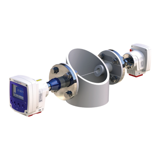
Laser receiver Process gas O-ring Adjustable mount (2 variants) Fixed mount Laser transmitter Gasket Non-visible laser beam path Process pipe, stack, duct, etc. Figure 2-1: 07931-Series Laser example installation (exploded view) © Servomex Group Limited. 2015 07931001A revision 1... -
Page 17: Figure 2-2: 07931-Series Laser Installation: Showing Insertion Tube, Thermal Spacer And Isolation Flange Options
TU side. Items 8, 9 and 10 are optional, additional gaskets and adaptors may be required. Figure 2-2: 07931-Series Laser installation: showing insertion tube, thermal spacer and isolation flange options 07931001A revision 1 © Servomex Group Limited. 2015... -
Page 18: Transmitter Unit
Cable entry glands: (option) 2 x M16 x 1.5 mm (ports 2 and 3) 2 x M20 x 1.5 mm (ports 1 and 4) Figure 2-3: Transmitter unit: front, rear, side and under-side views © Servomex Group Limited. 2015 07931001A revision 1... - Page 19 Two additional status relay outputs Customer connection terminals Accessible terminals are provided for: 24 V DC power feed Analog inputs (1 or 2) Analog outputs (0, 1 or 2) Relays (1 or 3) Ethernet 07931001A revision 1 © Servomex Group Limited. 2015...
-
Page 20: Receiver Unit
Purge 3: enclosure environmental out or Window purge out breather (option) (option: isolation flange only) Fixed mount (illustrated) may alternatively be configured with an adjustable mount Figure 2-4: Receiver unit: front, rear, side and under-side views © Servomex Group Limited. 2015 07931001A revision 1... -
Page 21: Figure 2-5: Receiver Unit Indicators
Laser adjustment (usually OFF) Illuminated Amber during alignment Laser light ON Illuminated Green when laser beam is on Laser adjustment (usually OFF) Illuminated Amber during alignment Laser adjustment (usually OFF) Illuminated Amber during alignment 07931001A revision 1 © Servomex Group Limited. 2015... -
Page 22: Mounting Assembly (Flange And Window Purge)
Input connector: 3+PE, Cable outlet (mm): 12-14, wire gauge (max AWG): 14 Output connector: 6+PE, Cable outlet (mm): 12-14, wire gauge (max AWG): 16 *For further details refer to www.tracopower.com/products/tex120.pdf Product specifications 2.6.1 Physical dimensions Figure 2-6: Transmitter unit dimensions © Servomex Group Limited. 2015 07931001A revision 1... -
Page 23: Figure 2-7: Receiver Unit Dimensions
Purge 2 (enclosure environmental in) Female 1/8” NPT Female 1/8” NPT pipe connector pipe connector Purge 3 (enclosure environmental Female 1/8” NPT Female 1/8” NPT out) pipe connector pipe connector 07931001A revision 1 © Servomex Group Limited. 2015... - Page 24 Maximum process flange 135 °C (275 °F) temperature (classified process): In-situ response time: Application dependent Drift: Application dependent Repeatability: ± detection limit or ± 1% of reading, whichever is greater Linearity: <1% FSR © Servomex Group Limited. 2015 07931001A revision 1...
-
Page 25: Additional Information
Rolling average up to 24 hours (exponential decay). For general commissioning activities the analyser will be functional within 10 minutes, however Servomex recommend allowing 3 hours for the analyser to stabilise. Additional information The following specifications are dependent on the configuration of the 07931-Series Laser that you originally purchased. -
Page 26: Materials In Contact With The Sample
316 stainless steel Insertion tube: 316 stainless steel O-rings: Fluorocarbon Chemras 505 (optional) Process flange gasket: Stainless steel and graphite composite Optical window: Fused silica (optical coating) Optical window seal: Loctite 595 © Servomex Group Limited. 2015 07931001A revision 1... -
Page 27: Unpacking
21% or equivalent at elevated pressure. everything for any damage that may have occurred during transit. If any item has been damaged, contact Servomex or its agent straight away. Keep all packaging and shipping information. Check that the parts supplied agree with your purchase specification. -
Page 28: Transmitter User Interface
The transmitter unit front panel contains the following indicator LEDs: Function Colour Fault Illuminated amber when a fault is raised Laser light ON Illuminated green when laser beam is on Alarm Illuminated red when an alarm is raised © Servomex Group Limited. 2015 07931001A revision 1... -
Page 29: Start-Up Screen
Figure 3-3: Example of a ‘live’ measurement screen Item Measurement number Soft key navigation icons Measurement designation System status icon Measurement units Measurement status icons Live measurement reading Software health indicator Live transmission reading 07931001A revision 1 © Servomex Group Limited. 2015... -
Page 30: Soft Key Legends
Allows highlighted data to be edited Moves cursor up the list Down Moves cursor down the list Left Moves cursor to the left Right Moves cursor to the right Blank No effect © Servomex Group Limited. 2015 07931001A revision 1... -
Page 31: System And Measurement Status Icons
Warming Indicates the TU is warming up High alarm A high alarm for a specific measurement is activated Low alarm A low alarm for a specific measurement is activated 07931001A revision 1 © Servomex Group Limited. 2015... -
Page 32: Navigation And Selecting On-Screen Options
Increases highlighted digit by 1 Decreases highlighted digit by 1 Moves cursor left to previous digit Moves cursor right to next digit © Servomex Group Limited. 2015 07931001A revision 1... -
Page 33: Password Protection
It is strongly recommended that the highest level password is only used in emergencies to reset 'forgotten' lower level passwords. Note: If the highest level password is lost, it will be necessary to contact Servomex for recovery details. You must enter a password to access some options and screens. -
Page 34: Configuration Setting Types
This file will only be saveable by Technical users. It can be loaded by a Supervisor level user or above to facilitate recovery of an instrument that cannot be fixed by other means. © Servomex Group Limited. 2015 07931001A revision 1... - Page 35 To restore a date and time stamped measurement backup from the microSD card. 07931001A revision 1 © Servomex Group Limited. 2015...
- Page 36 The file can be saved / restored from internal memory or via the MicroSD card (or shortly loaded via the web interface). The file can be saved in pre-named configurations for specific purposes or in user named files. © Servomex Group Limited. 2015 07931001A revision 1...
- Page 37 This feature is able save all of the following options to internal memory Note: located on the Main PCB. The custom option can only be saved to a suitable microSD card. 07931001A revision 1 © Servomex Group Limited. 2015...
- Page 38 The Save Current Config menu will present 3 options: Operating default - to be used during normal operation Alternative – not normally required Custom – use to create exportable or multiple configurations during servicing and maintenance. © Servomex Group Limited. 2015 07931001A revision 1...
- Page 39 To restore a date and time stamped calibration backup from the microSD card. 07931001A revision 1 © Servomex Group Limited. 2015...
- Page 40 SD card. Hint: The configuration file can be transferred between instruments to minimise multiple analyser setup time. © Servomex Group Limited. 2015 07931001A revision 1...
- Page 41 Status log Analyser configuration parameters Transducer configuration parameters Graphical spectral data System log (Servomex access only) 3.10.4 Saving a support package To save a support package: User settings Save support package Network settings Storage location Password...
-
Page 42: Menu Structure
View detailed internal laser measurement data mA output View enabled mA input details mA input View input power supply details Relay overide Override / calibrate analogue output Enable calibration of analogue input Overide relay state © Servomex Group Limited. 2015 07931001A revision 1... -
Page 43: Configuration
Input Data log mA input 1 (-----) 2 (-----) Alarms mA output 1 (-----) Status Relay set up select mA input Set up Filtering Measurement Unit Select Service X-Interfere Clipping User settings 07931001A revision 1 © Servomex Group Limited. 2015... - Page 44 User settings Once the mA input has been enabled it will need to be configured. The mA input parameters that must be set up are illustrated in Figure 4-1: mA input sequential menu. © Servomex Group Limited. 2015 07931001A revision 1...
-
Page 45: Figure 4-1: Ma Input Sequential Menu
Out of range state Message Maintenance required select option Out of spec Service in progress Fault Filter time 0.000 sec edit time Reset threshold 100 Pa edit Figure 4-1: mA input sequential menu 07931001A revision 1 © Servomex Group Limited. 2015... - Page 46 Sets the threshold where you want the filter to ‘collapse’ and revert to a non-filtered state until the Reset threshold change in reading falls back below the reset threshold (currently selected units apply) © Servomex Group Limited. 2015 07931001A revision 1...
-
Page 47: Process Environment Settings "Physical Set Up
Note: When the laser, measurement signals have been optimised and the process environment set up have been completed Servomex recommend saving the configuration. The physical parameters that must be set up are illustrated in the following sequential menu table:... -
Page 48: Figure 4-3: Purged Cross Stack Path Length Example
2 common installation configurations. Path length Purged length Purged length Figure 4-3: Purged cross stack path length example Path length Purged length Purged length Figure 4-4: Non purged isolation flange cross stack path length example © Servomex Group Limited. 2015 07931001A revision 1... -
Page 49: Figure 4-5: Purge Compensation Segments
140 mm + Receiver enclosure (RxEnc) 39 mm Figure 4-5: Purge compensation segments To enable purge compensation 1 Xxxx Physical Setup 1 Xxxx Physical Setup Purge Compensation Purge Compensation Disabled Disabled Enabled Enable 07931001A revision 1 © Servomex Group Limited. 2015... -
Page 50: Figure 4-6: Purge Compensation Sequential Menu
1 Xxxx Physical Setup Proc: TxEnc: Concentration User defined 0-4 select option TxEnc Temp source 20.90% Transmitter Enclosure Reciever Enclosure 1 Xxxx Physical Setup Proc:Temp Source Internal Figure 4-6: Purge compensation sequential menu © Servomex Group Limited. 2015 07931001A revision 1... - Page 51 The thermistor will measure the temperature inside the enclosure. Option 4: Receiver enclosure The receiver enclosure is fitted with a thermistor mounted on the main process PCB. The thermistor will measure the temperature inside the enclosure. 07931001A revision 1 © Servomex Group Limited. 2015...
-
Page 52: User Settings
If an environmental purge is fitted, the value reported may be lower than the ambient temperature, and an addition to the calculated offset should be applied. When the physical or user settings have been completed Servomex Note: recommend saving the configuration. See section 3.10 User settings 4.3.1... -
Page 53: Figure 4-8: Password Sequential Menu
It is strongly recommended that the highest level password is only used in emergencies to reset 'forgotten' lower level passwords. Note: If the highest level password is lost, it will be necessary to contact Servomex for recovery details. Note: Passwords can only be changed for the currently selected security level or lower. - Page 54 You can set the date format to dd/mm/yy or mm/dd/yy in the regional settings (section 4.3.4). Note: After power cycle, review system time and date.to ensure consistency with your own system time. © Servomex Group Limited. 2015 07931001A revision 1...
-
Page 55: Figure 4-9: Regional Settings Sequential Menu
/ s Current select units Voltage select units Resistance select units kOhm Angle select units º Wavelength select units Moisture dew pt ºC select units Figure 4-9: Regional settings sequential menu 07931001A revision 1 © Servomex Group Limited. 2015... - Page 56 ‘back light time’ it will then switch off. Note: The timer is reset each time you press a soft-key, so the backlight remains on for the set time after the last soft-key press. © Servomex Group Limited. 2015 07931001A revision 1...
- Page 57 Save Current Config soft keys User settings Restore Config Delete Config Save Support Package Information Note: When you select the brightness setting the screen displays a non- editable alpha / numeric screen pattern. 07931001A revision 1 © Servomex Group Limited. 2015...
- Page 58 SD card. Hint: The configuration file can be transferred between instruments to minimise multiple analyser setup time. © Servomex Group Limited. 2015 07931001A revision 1...
-
Page 59: Configure Ma Outputs
4 -20 mA and jam low (default setting) for safety and to prevent any analyser faults going undiagnosed. This is the safest mode of operation. 07931001A revision 1 © Servomex Group Limited. 2015... -
Page 60: Figure 4-10: Ma Output Sequential Menu
Set up 1 (-----) 2 (-----) Alarms mA output 1 (-----) Status Relay set up select mA input Set up Filtering Measurement Unit Select Service X-Interfere Select System log Clipping User settings © Servomex Group Limited. 2015 07931001A revision 1... - Page 61 When more than one range is used, range 2 needs to be set to the higher range. Once the mA Output channel and range has been selected the final configuration parameters will need to be set. 07931001A revision 1 © Servomex Group Limited. 2015...
- Page 62 3.8 mA, where an output between 3.8 mA and 4 mA indicates a negative gas concentration The range change-point Range change point This is only available when auto range is selected The range change hysteresis Hysteresis This is only available when auto range is selected © Servomex Group Limited. 2015 07931001A revision 1...
- Page 63 The actual mA output value is controlled from the mA output calibrate screen as long as the screen is displayed. As soon as the mA service screen is no longer displayed, the mA output value will be updated to reflect the corresponding measurement. 07931001A revision 1 © Servomex Group Limited. 2015...
-
Page 64: Configure Relay Outputs
3 TU 3 O.o.S 4 TU 4 Fault 4 TU4 Maint 4 TU 4 S.I.P 4 TU4 O.o.S mA out 1 range mA out 2 range Low alarm High alarm Alarm 1 Alarm 25 © Servomex Group Limited. 2015 07931001A revision 1... - Page 65 1 or more High Alarm thresholds have been exceeded User configurable alarms that can be assigned to a Alarm 1 to 25 relay event Repeat this option selection process for each of the 4 available events. 07931001A revision 1 © Servomex Group Limited. 2015...
- Page 66 Alarms mA output Status Relay set up Set up Filtering Measurement Unit Select Service X-Interfere Clipping Relay setup Relay setup User settings Relay 1 active Relay 1 active Energised Energised Deenergised © Servomex Group Limited. 2015 07931001A revision 1...
-
Page 67: Filtering
% mg/m3 mg m-3 (milligrams per normal cubic metre) mol/mol mols per mol (or moles per mole) % LEL volume % of the Lower Explosive Limit 07931001A revision 1 © Servomex Group Limited. 2015... -
Page 68: X-Interference Offset
Measurement Unit Select Service X-Interfere Clipping User settings Clipping When enabled, clipping is applied to all instances of a measurement, including displayed values, mA output values and values accessible through digital communications. © Servomex Group Limited. 2015 07931001A revision 1... - Page 69 When enabled the facility is provided to raise an “Operation Out of Specification” status condition whenever the measurement value exceeds an enabled clipping level. This status shall persist if a clipping override level is exceeded. 07931001A revision 1 © Servomex Group Limited. 2015...
-
Page 70: Configure Measurement Alarms
An alarm is raised when a sample measurement is higher than the pre-set alarm level High alarm Note: An alarm is only activated during calibration if you have set the alarm ‘Follow’ option to Yes © Servomex Group Limited. 2015 07931001A revision 1... - Page 71 To assign alarm to a measurement Alarms Alarm 1 : O2 Alarm 1 : O2 Unlatch Alarm Measurement Active Set up 1 (Tx 1) 2Trans % Follow 3______ History 4______ select measurement 1 to 4 07931001A revision 1 © Servomex Group Limited. 2015...
- Page 72 Alarm 1 : O2 Alarm 1 : O2 Alarm 1 : O2 Alarm 1 : O2 Unlatch Alarm Measurement Mode Latching Active Set up 1 (Tx 1) 2Trans % None Follow History select mode © Servomex Group Limited. 2015 07931001A revision 1...
- Page 73 Alarm 1 : O2 Alarm 1 : O2 Alarm 1 : O2 Unlatch Alarm Measurement Mode Latching Level Active Set up 1 (Tx 1) 2Trans % None Follow 0.00% History edit level 07931001A revision 1 © Servomex Group Limited. 2015...
- Page 74 If the 'Follow' option is set to 'Yes', the alarm will not be inhibited during calibration. To set follow option Alarms Follow O2 LT Follow O2 LT Follow Unlatch 1 O2 LT Follow Follow Active 2 Trans Set up Follow History © Servomex Group Limited. 2015 07931001A revision 1...
-
Page 75: Gain And Phase Settings
Gain and phase settings DC gains 1 and 2 enable the signal to be optimised for the specific application; in addition the phase of the measurement signal and reference burst must also be optimised. 07931001A revision 1 © Servomex Group Limited. 2015... - Page 76 DC Gain 1 and DC Gain 2 is set during manufacturing and should only be changed by a Servomex trained engineer. 4.11.2 To adjust DC Gain 1 settings 4.11.3 To adjust gain 2 settings © Servomex Group Limited. 2015 07931001A revision 1...
-
Page 77: Figure 4-11: Raw Signal Graph Example
Adjust burst phase cal When the correct DC Voltage is achieved it is possible to synchronise the phase timing of the reference burst signal ref Figure 4-11(ABurst) by selecting ‘Adjust Burst Phase Cal’. 07931001A revision 1 © Servomex Group Limited. 2015... - Page 78 Measurement signal Toggle between these 2 menus Physical setup Detailed setup Save current config Measurement signal SigWid (Signal width) Check Signal Amplitude < 100000 SigAmp (Signal amplitude) Filtered Graph Adjust Gas Phase © Servomex Group Limited. 2015 07931001A revision 1...
-
Page 79: Figure 4-12: Filtered Graph Example
When an adiquate signal amplitude is achieved check the signal filtered graph shape. The measurement signal must then be optimised by selecting ‘Adjust Gas Phase ref.4.11.5 Figure 4-12: Filtered Graph example For trace level applications the peak may appear as a flat line. Note: 07931001A revision 1 © Servomex Group Limited. 2015... -
Page 80: General Analyser Information
The message type ("Fault", "Maintenance rqd" or "Service in Progress") The message itself The status of the entry "ON" or "OFF" 5.1.3 Export history The current stored history log will be exported to the selected log media. © Servomex Group Limited. 2015 07931001A revision 1... -
Page 81: Measurement
Measurement and units Calibrated current Filtered current Unfiltered current 5.2.3 Control unit power Provides information on Input supply power and 12 V rail. 5.2.4 Graphs Shows raw data and filtered graphs for each measurement. 07931001A revision 1 © Servomex Group Limited. 2015... -
Page 82: Data Log
Data log filename is ‘datalog.txt’ on microSD card Example Data log: Servomex 07931A1/000051 ; O2 LT ; Trans ; Temperature ; Pressure 1.7 ; 24/04/15 ; 11:50:07 ; O2 LT ; 20.76 ; % ; ; Trans ; 101.08 ; % ;... -
Page 83: Log Run Mode
Interval Units Data log Detailed Log Log Interval Hours Alarms Log Full Seconds Minutes Select Status View Log Seconds Set up Clear Log Measurement Log Media Service Export Interval Mins 001 Edit value 07931001A revision 1 © Servomex Group Limited. 2015... -
Page 84: Log Full
The view log page enables the current log to be scrolled through so each data point can be viewed. Clear log Clear log will clear the current log stored in the selected media. You will be asked to confirm the action before clearing. © Servomex Group Limited. 2015 07931001A revision 1... -
Page 85: Log Media
When inserting or removing the SD card take care not to accidentally remove the metal card holder as, when open, the holder can slide backwards / out and be disconnected from the PCB. Before closing the enclosure ensure the holder is secure. 07931001A revision 1 © Servomex Group Limited. 2015... -
Page 86: Figure 6-2: Micro Sd Connector
When inserting or removing the SD card take care not to remove the metal card holder as, when open, the holder can slide backwards and out. And be disconnected from the PCB. To open the cover, slide the latch to the left. © Servomex Group Limited. 2015 07931001A revision 1... - Page 87 Insert the micro SD card into the slots in the cover. Close the cover and push the latch to the right to secure it. The SD card connector is used for: Data logging Software updates Settings (save / restore) 07931001A revision 1 © Servomex Group Limited. 2015...
-
Page 88: Calibration
The analyser is factory calibrated using a certified gas mixture and is supplied with a calibration test report. Servomex recommend that you verify the calibration of the instrument annually, using a certified test gas and the supplied calibration gas cell. -
Page 89: Removing The Transmitter And Receiver Units From The Process
Dismount TU and RU by loosening the 3 mounting bolts Place window cover on TU and RU Mount blanking plates on mounting / alignment assembly Move to calibration area 07931001A revision 1 © Servomex Group Limited. 2015... -
Page 90: Connecting Transmitter And Receiver Units To The Calibration Cell
The pressure in the calibration cell shall not exceed 1.5 bar absolute. Before using the calibration cell, ensure all connections are leak free at operating pressure. © Servomex Group Limited. 2015 07931001A revision 1... - Page 91 1 minute for the readings to stabilise and then perform calibration. In this case the gas pressure is equal to the ambient pressure. 07931001A revision 1 © Servomex Group Limited. 2015...
-
Page 92: Calibration
0-4 Internal Temp source Edit Offset or value Detailed set up For Servomex trained Service operators only Save Current Config Restore Config Delete Config Figure 7-2: Physical setup sequential menu Check photodiode DC voltage and signal amplitude. Adjust if required. - Page 93 “Target” refers to the target concentration of the calibration gas. Note: “Tolerance” refers to the tolerance of the measured reading against the “Target” concentration. A warning will be indicated if the measured 07931001A revision 1 © Servomex Group Limited. 2015...
- Page 94 X- interference requires “Supervisor” password or above. 7.4.4 Calibrate Note: Before you attempt to calibrate the system, let the instrument operate for at least 3 hours. Note: Before calibration proceeds clipping function should be disabled if active. © Servomex Group Limited. 2015 07931001A revision 1...
- Page 95 15 minutes at flows between 500 ml to1000 ml/min. The customer must enter 0 in the box called CAL1C and enter all the 07931001A revision 1 © Servomex Group Limited. 2015...
- Page 96 7.4.5 Saving calibration configuration Menu Calibrate Calibrate Settings Data log Calibrate Alarms Validate Status Veiw History Set up Export History Measurement Clear History Service Save Current Config Restore Config Delete Config © Servomex Group Limited. 2015 07931001A revision 1...
-
Page 97: In Situ Validation (In-Line Span Or Zero Check)
Switch on zero gas to purge in-line span cell for a minimum of 5 minutes. The baseline subtraction function should then be used to zero out the analyser before validation gas is introduced to the in-line span cell. 07931001A revision 1 © Servomex Group Limited. 2015... - Page 98 0.5% Note: Reading must be allowed to stabilize for a minimum of 5 minutes. Purge the cell with zero gas and confirm zero reading again and remove baseline subtraction. © Servomex Group Limited. 2015 07931001A revision 1...
-
Page 99: Installation
RJ45 connectors and crimping Cable connections tool Micro SD card Backing up post commissioning Note: Other wrenches required as appropriate for M16 and M20 cable glands, adaptors and/or conduit being fitted. 07931001A revision 1 © Servomex Group Limited. 2015... - Page 100 Cabling exiting the Analyser should also be considered. Each unit requires at least 500 mm (19.7 ") of free space (measured from flange to the stack and outwards). © Servomex Group Limited. 2015 07931001A revision 1...
-
Page 101: Figure 8-2: 07931-Series Laser Installation Distances
The 07931-Series Laser attaches to process flanges that you must weld either to the relevant process pipework, duct or furnace wall or, for pipework up to 150 mm (6 ") in diameter, to a spool piece supplied by Servomex. You can attach the laser analyser mounting assemblies (fixed or adjustable) to the process flange either directly with appropriate gaskets, or via an isolation valve or an isolation window, depending on your application. -
Page 102: Figure 8-3: 07931-Series Laser Flange Dimensions
07931-Series Laser is fixed does not exceed 135 °C (275 °F). Servomex can provide thermal spacers for a range of flange sizes. Hint: It is important that the process flanges are aligned correctly as they are critical to ensuring the successful alignment and maximum transmission of the 07931-Series Laser. - Page 103 2 planes. So that this operates correctly after the instrument is installed, use the following tolerances for positioning and attaching the process flanges. 07931001A revision 1 © Servomex Group Limited. 2015...
-
Page 104: Figure 8-4: Process Flange Bolt Arrangement (4 Bolt Pattern)
Figure 8-4: Process flange bolt arrangement (4 bolt pattern) The flange bolt pattern must be: 4 bolt pattern 45 ° 8 bolt pattern 22.5 ° (not shown) © Servomex Group Limited. 2015 07931001A revision 1... -
Page 105: Figure 8-5: Process Flange Positioning Tolerance
Figure 8-5: Process flange positioning tolerance Note: Failure to align the transmitter and receiver flanges may adversely affect the performance. Tolerance to misalignment is dependent on divergence, path length and measurement. For further advice contact Servomex or local representative. 8.1.5 Optional flange alignment jig Never look into a live process through the eye piece as this may result in hazardous radiation exposure and permanent eye damage. -
Page 106: Figure 8-6 Flange Alignment Adaptor
Secure each flange with one tack weld. The clearance should enable an adjustment of at least ± 2º in each direction for all flange sizes. © Servomex Group Limited. 2015 07931001A revision 1... - Page 107 13) Fit the alignment tool light source assembly to the adaptor on the other process flange as described in point 5), if applicable. 14) Repeat steps 8) and 9) to align and secure the second process flange. 07931001A revision 1 © Servomex Group Limited. 2015...
- Page 108 It MUST NOT be used where an EXPLOSIVE atmosphere is present in the ‘outside atmosphere’ or the ‘Process atmosphere’. The alignment tool shall not be used where there is a risk of exposure to hazardous gases contained in the process. © Servomex Group Limited. 2015 07931001A revision 1...
- Page 109 Always allow for the weight of the cable in addition to the weight of the TU and RU. The 'free-hanging' un-supported weight of cables should not exceed the weight of the unit. 07931001A revision 1 © Servomex Group Limited. 2015...
-
Page 110: Figure 8-8: Transmitter Unit Mounting Arrangement (Example Shown With Adjustable Mount)
9.0 kg (19.8 lb) Figure 8-8: Transmitter unit mounting arrangement (example shown with adjustable mount) If the process wall is not strong enough to support the TU or RU, Servomex recommend that you use a reinforcement plate. Note: It is your responsibility to assess and design the reinforcement plate that you will use in your installation, subject to local conditions. -
Page 111: Installation Overview
This section gives an overview of the installation procedures. It details the signal inputs and outputs available in the 07931-Series Laser transmitter and receiver units, and outlines any conditions of use that you should consider before you install the instrument. 07931001A revision 1 © Servomex Group Limited. 2015... - Page 112 © Servomex Group Limited. 2015 07931001A revision 1...
-
Page 113: Figure 8-10: Installation Overview
The equipment is incapable of passing the dielectric strength test prescribed by the standards, and so this must be taken into account during installation. 07931001A revision 1 © Servomex Group Limited. 2015... -
Page 114: Figure 8-11: 07931-Series Laser In-Situ Installation
Make sure that the flanges on the process walls are mounted and aligned correctly (Section 8.1). Transmitter unit Transmitter alignment assembly Process flange Process flange Receiver mounting / alignment assembly Receiver unit Figure 8-11: 07931-Series Laser in-situ installation © Servomex Group Limited. 2015 07931001A revision 1... -
Page 115: Process Connections
Ensure flange o-rings are fitted to the analyser mounting flanges. Note: Orientate the mounting assembly so that the purge connections are pointing to the left (as viewed looking at the process wall) to ensure the TU and RU mount vertically. 07931001A revision 1 © Servomex Group Limited. 2015... -
Page 116: Figure 8-12: Example Of Mounting / Alignment Assembly Fitting Exploded View
Do not use the alignment tool if the process flange is hot (> 60 °C), or if the process contains potentially hazardous gases. Only use the light source supplied by Servomex with the alignment tool. Make sure that there are no dangers from the release of potentially hazardous gases, for example, toxic, flammable, asphyxiant or hot gases. - Page 117 Taking care not to change the position of the assembly during step 5 and 6. Hint: Step 6 Remove the alignment tool scope assembly and replace the boot immediately Step 7 Switch off the alignment tool light source assembly and remove it from the RU 07931001A revision 1 © Servomex Group Limited. 2015...
- Page 118 Check the o-ring is in place on the transmitter / receiver flange before installation. Loosen the 3 x M6 screws and align them with the corresponding keyhole slots on the flange joint (Figure 8-13). © Servomex Group Limited. 2015 07931001A revision 1...
-
Page 119: Figure 8-13: Align M6 Screws With The Flange Joint
Figure 8-13: Align M6 screws with the flange joint Rotate the enclosure until it stops at the end of the keyhole slots. Figure 8-14: Rotate the enclosure 07931001A revision 1 © Servomex Group Limited. 2015... -
Page 120: Figure 8-15: Tighten The M6 Screws
Tighten the 3x M6 screws to secure the flange. 3 x M6 screws Figure 8-15: Tighten the M6 screws © Servomex Group Limited. 2015 07931001A revision 1... -
Page 121: Electrical Connections
Replace and secure all covers as soon as possible after you complete your task within the enclosure. Disconnect all cables from the 07931-Series Laser when you carry out insulation testing on them. 07931001A revision 1 © Servomex Group Limited. 2015... -
Page 122: Figure 8-16: Cable Screen Terminations
Cable screens Transmitter unit Receiver unit Figure 8-16: Cable screen terminations © Servomex Group Limited. 2015 07931001A revision 1... -
Page 123: Figure 8-17: Cable Strip Lengths
Figure 8-17: Cable strip lengths Cable gland and blanking plug sizes Receiver unit Use one M20 x 1.5 mm cable gland in the receiver unit. Figure 8-18: Receiver unit cable gland position 07931001A revision 1 © Servomex Group Limited. 2015... -
Page 124: Functional Earth / Ground Requirements
Make sure that the electrical supply voltage shown on the rating label is correct for the available electrical supply. Do not install the equipment if the incorrect voltage is shown and contact Servomex or your local Servomex agent immediately. © Servomex Group Limited. 2015... - Page 125 Cable external diameter Within the range specified for the selected cable gland (opt. power supply selected, 14mm (Max)) Note: Under certain conditions of high ambient temperature a higher temperature rated cable may be required. 07931001A revision 1 © Servomex Group Limited. 2015...
-
Page 126: Figure 8-20: Opening The Transmitter Unit
To open the transmitter unit, loosen the 4x M4 captive screws on the front panel (A in). The front panel hinges open (B in) to show the electronics and connectors. Figure 8-20: Opening the transmitter unit © Servomex Group Limited. 2015 07931001A revision 1... -
Page 127: Figure 8-21: 7-Way Main Terminal And Entry Glands
18 to 30 V DC (nominally 24 V DC) Relay N/O Relay COM Relay N/C mA Output + mA Output - Screw terminal torque 0.2-0.25 Nm Figure 8-21: 7-way main terminal and entry glands 07931001A revision 1 © Servomex Group Limited. 2015... -
Page 128: Figure 8-22: 8-Way Transmitter To Receiver Connector
(Twisted Pair 3) Signal 1 - (Measurement) (Twisted Pair 3) Signal 2 + (Twisted Pair 4) Signal 2 - (Twisted Pair 4) Screw terminal torque 0.2-0.25 Nm Figure 8-22: 8-way transmitter to receiver connector © Servomex Group Limited. 2015 07931001A revision 1... - Page 129 Cable external diameter Within the range specified for the selected cable gland Maximum length 100 m Note: Under certain conditions of high ambient temperature a higher temperature rated cable may be required. 07931001A revision 1 © Servomex Group Limited. 2015...
-
Page 130: Figure 8-23: Ethernet Connections
Short connector covers are recommended as internal space is limited and large or long covers may be difficult to fit. Hint: Installation of an Ethernet cable to a designated area suitable for remote connection to a PC is recommended. © Servomex Group Limited. 2015 07931001A revision 1... -
Page 131: Figure 8-24: 12-Way Options Board Connections
Screw terminal torque 0.2-0.25 Nm Figure 8-24: 12-way options board connections All unused screw clamps must be tightened. Ensure connector latches “click” and are engaged fully. Note: These connections are included on an optional PCB. 07931001A revision 1 © Servomex Group Limited. 2015... -
Page 132: Purge Connections
07931-Series Laser optics could be damaged by the hot process. Hint: Servomex recommend that the purge gas is supplied using flexible piping to minimise strain on the alignment assembly. The instrument windows are kept clean by setting up a positive flow of air through the alignment / purging flanges and into the stack. -
Page 133: Figure 8-25: Transmitter Purge
Purge 2 – Enclosure environmental IN (only if a measurement purge is also required) or blanking plug Purge 1 – Measurement or environmental IN (max 100ml min or blanking plug Figure 8-25: Transmitter purge 07931001A revision 1 © Servomex Group Limited. 2015... -
Page 134: Figure 8-26: Receiver Purge
Breather - DO NOT BLANK Purge 2 – Enclosure environmental IN (only if a measurement purge is also required) or blanking plug Purge 1 – Measurement or environmental IN, or blanking plug Figure 8-26: Receiver purge © Servomex Group Limited. 2015 07931001A revision 1... - Page 135 0.1 litres/minute (0.004 cubic ft/min) to avoid pressure build up inside the units. Note: Some instrument air may contain some oil and water which will quickly damage the optical windows, mirrors and lens in the receiver and transmitter units. 07931001A revision 1 © Servomex Group Limited. 2015...
-
Page 136: Commissioning
Purge panel flow meters are set to recommended flow rates for the specific application and recorded (Flows should be verified at the Analyser to ensure there are no leaks or splits in the lines. Table 8-2: Mechanical installation check list © Servomex Group Limited. 2015 07931001A revision 1... - Page 137 Alignment for optimum measurement Overview Note: The 07931-Series Laser is factory calibrated however Servomex recommend the Analyser is locally calibrated before installation. The transmission optimisation process is an iterative process required to be completed when the unit is in situ and should be completed before final measurement commissioning steps and software configuration.
-
Page 138: Figure 8-27: Peel Back The Boot
A, B, C and D ( Figure 8-28), taking care not to change the position of the assembly. Step 6 Adjust Phase busrt cal See section 4.11.5 Figure 8-27: Peel back the boot © Servomex Group Limited. 2015 07931001A revision 1... -
Page 139: Figure 8-28: Installation: Ball-Joint Adjustment Screws
Depending on application details it may be required to readjust the photodiode DC level several times to ensure the target DC voltage level does not exceed 2.7 volts. To check the DC voltage level refer to 4.11.1. 07931001A revision 1 © Servomex Group Limited. 2015... -
Page 140: Figure 8-29: Installation: Adjust Laser Intensity On The Photodiode
Adjustment in the correct Adjustment in the wrong direction. direction. Shows power ON. Tuning target voltage met. Possible laser hazard. Figure 8-29: Installation: adjust laser intensity on the photodiode © Servomex Group Limited. 2015 07931001A revision 1... - Page 141 4.2.2 Configure the process temperature settings 4.2.3 Configure the mA outputs Configure the relays Configure filtering options Configure measurement alarms 4.10 3.10.4 Save settings 4.3.8, 7.4.5 Table 8-5: Measurement configuration check list 07931001A revision 1 © Servomex Group Limited. 2015...
-
Page 142: Service
Output Calibrate mA Output Overide mA Output mA Output Data log mA Input Calibrate Alarms Relay Override Status Set up Measurement Select Service mA Output mA Output Calibrate Calibrate 20.000 mA Select © Servomex Group Limited. 2015 07931001A revision 1... - Page 143 Setpoint 1 Apply 2.000 mA Select mA Input mA Input Setpoint 2 (High) Setpoint 2 20.00 mA 20.00 mA Edit Value mA Input Setpoint 2 Apply 20.00 mA Select mA Input Calibrate Calibrate Select 07931001A revision 1 © Servomex Group Limited. 2015...
- Page 144 Save current config Phase/Gain Settings Alarms mA output Restore config Measurement signal Select Status Relay set up Delete config Physical setup Set up Filtering Detailed setup Measurement Unit Select Service X-Interfere Clipping User settings © Servomex Group Limited. 2015 07931001A revision 1...
-
Page 145: Routine Maintenance
Sample gases may be toxic, asphyxiant or flammable. Before you remove the 07931-Series Laser from the process, make sure that it does not contain any potentially hazardous or heated gases, or is at a pressure below atmospheric pressure. 07931001A revision 1 © Servomex Group Limited. 2015... -
Page 146: Cleaning
(option), or via a warning relay. 9.4.2 Weekly Check purge flow rates Use a flow meter on the purge panel to check the purge flow rates are the same as at the time of commissioning. © Servomex Group Limited. 2015 07931001A revision 1... -
Page 147: Alignment / Purging Flanges
User replaceable spare parts There are no user replaceable spare parts. All 07931-Series Lasers returned to Servomex or one of its appointed agents for servicing, disposal, or any other purpose must be accompanied by a completed decontamination certificate. -
Page 148: Certification Information
Ex ic nA nC op is IIC T4 Gc Ex tb IIIB T135°C IP66 Db Ambient Temperature range -20 °C to +65 °C Certification number (ATEX) Baseefa14ATEX0193X Certification number (IECEx) IECEx BAS 14.0092X © Servomex Group Limited. 2015 07931001A revision 1... -
Page 149: Label Information
Class III, Div 1 T4 Class I, Zone 2, Group IIC T4 Enclosure IP66, 4X Ambient Temperature range -20 °C to +65 °C SGS Contract number 710216 10.2 Label Information Figure 10-1: ATEX / IECEx labels 07931001A revision 1 © Servomex Group Limited. 2015... -
Page 150: Emc
Cet appareil ISM est conforme à la norme NMB-001 du Canada. The 07931-Series Laser complies with Part 15 of the FCC Rules for Class A equipment. It is not suitable for operation when connected to a public utility © Servomex Group Limited. 2015 07931001A revision 1... -
Page 151: Electrical Safety
The 07931-Series Laser has been assessed to IEC61010-1 for electrical safety including any additional requirements for US and Canadian national differences. Overvoltage Category: Category II. Pollution Degree: 2. Servomex Group Limited is a BS EN ISO 9001 and BS EN ISO 14001 certified organisation. 10.5 Product Disposal This product is not considered to be within the scope of the Waste Electrical and Electronic Equipment (WEEE) Directive. - Page 152 For information on Substances of Very High Concern (SVHCs) included in Servomex products see: www.servomex.com © Servomex Group Limited. 2015 07931001A revision 1...
-
Page 153: Index
12-way option board connector process connections ......112 ..........127 alignment / purging flanges 7-way main connector.....123 align ........113 8-way transmitter/receiver unit fit ....... 19, 26, 112 connector .......124 fit the analyser ......115 07931001A revision 1 © Servomex Group Limited. 2015... - Page 154 Transmitter Unit Indicator LEDs ....26 certification warnings Transmitter user interface......26 hazardous area installations ..9 unpacking ..........25 hazardous area variants ..10 flange assembly .......20 general warnings ......8 User settings ...........50 laser safety.........9 markings ........11 © Servomex Group Limited. 2015 07931001A revision 1...
-
Page 155: Appendix Display Unit Conversion Factors
Selected display units This conversion is not supported Note: To return to the measurement default units, select the "off" units selection option and set the units conversion factor to "1": see Section 4.7 07931001A revision 1 © Servomex Group Limited. 2015... -
Page 156: Appendix Modbus Setup
If an error should occur while processing a message one of the following exception codes will be returned by the instrument. Code Condition Meaning Illegal function Requested function code is not supported. © Servomex Group Limited. 2015 07931001A revision 1... - Page 157 31, in the first register, and the least significant word, bits 0 – 15, in the next register. This order can be reversed by setting a coil in the system control mapping. 07931001A revision 1 © Servomex Group Limited. 2015...
- Page 158 Number Of Network Cards NumberOfResources 13.1.7 System Settings Supports Function Code Base Block Base Parameter Address Address Offset 2001 Floating point order User interface busy Disable user interface Audible alarm ResponseDelay Language © Servomex Group Limited. 2015 07931001A revision 1...
- Page 159 Base Block Base Parameter Address Address Offset Service in Progress 0=Not in Service Mode, 1=Service Mode. Instrument MUST be set to Service in Progress before any calibration or override actions are performed 07931001A revision 1 © Servomex Group Limited. 2015...
- Page 160 AVFailState 0=Not in Fail State, 1=In Fail State 13.1.11 TU Live info Supports Function Code First Base Base Block Address Address Number Block Offset Parameter 6961 Tx (4n-1) Transducer Type Tag Number Name Measurement Pressure Compensated Measurement Filtered Measurement © Servomex Group Limited. 2015 07931001A revision 1...
- Page 161 Incorrect transducer type 13.1.12 TU Settings Supports Function Code First Base Base Block Address Address Number Block Offset Parameter 12881 Tx (n) Name Units 14001 Filter Time Filter Reset Threshold Unit selection (scaling Factor) 07931001A revision 1 © Servomex Group Limited. 2015...
- Page 162 TU Control Supports Function Code Base Base Address Address Block Offset Parameter 4001 Calibration mode on/off Reserved Reserved Capture and enable baseline subtraction 4021 Invoke calibration n Calibration point n gas Reserved © Servomex Group Limited. 2015 07931001A revision 1...
Need help?
Do you have a question about the SERVOTOUGH LaserSPII mini and is the answer not in the manual?
Questions and answers