
Related Manuals for Meinberg LANTIME M150/GPS


Summary of Contents for Meinberg LANTIME M150/GPS
- Page 1 TECHNICAL REFERENCE LANTIME M150/GPS April 26, 2023 Meinberg Funkuhren GmbH & Co. KG...
-
Page 3: Table Of Contents
Table of Contents 1 Imprint 2 Copyright and Liability Exclusion 3 Presentation Conventions in this Manual Conventions for the Presentation of Critical Safety Warnings ....Secondary Symbols Used in Safety Warnings . - Page 4 11.3.2 Installation and Grounding ........11.4 Technical Specifications: Antenna Cable .
-
Page 5: Imprint
1 Imprint 1 Imprint Meinberg Funkuhren GmbH & Co. KG Lange Wand 9, 31812 Bad Pyrmont, Germany Phone: + 49 (0) 52 81 / 93 09 - 0 Fax: + 49 (0) 52 81 / 93 09 - 230 Website: https://www.meinbergglobal.com Email: info@meinberg.de... -
Page 6: Copyright And Liability Exclusion
Meinberg reserves the right to make changes of any type to this document at any time as is necessary for the purpose of improving its products and services and ensuring compliance with applicable standards, laws &... -
Page 7: Presentation Conventions In This Manual
3 Presentation Conventions in this Manual 3 Presentation Conventions in this Manual 3.1 Conventions for the Presentation of Critical Safety Warnings Warnings are indicated with the following warning boxes, using the following signal words, colors, and symbols: Caution! This signal word indicates a hazard with a low risk level. Such a notice refers to a procedure or other action that may result in minor injury if not observed or if improperly performed. -
Page 8: Conventions For The Presentation Of Other Important Information
3.3 Conventions for the Presentation of Other Important Information Beyond the above safety-related warning boxes, the following warning and information boxes are also used to indicate risks of product damage, data loss, and information security breaches, and also to provide general information for the sake of clarity, convenience, and optimum operation: Important! Warnings of risks of product damage, data loss, and also information security risks are indicated with... -
Page 9: Important Safety Information
Depending on your specific device configuration and installed options, some safety information may not be applicable to your device. Meinberg accepts no responsibility for injury or death arising from a failure to observe the safety information, warnings, and safety-critical instructions provided in the product documentation. -
Page 10: Product Documentation
Read the product manual carefully and completely before you set the product up for use. Safety standards and regulations change on a regular basis and Meinberg updates the corresponding safety information and warnings to reflect these changes. It is therefore recommended to visit the Meinberg website at https://www.meinbergglobal.com regularly to download up-to-date manuals. -
Page 11: Safety When Installing The Device
Never drill holes into the device to mount it! If you are experiencing difficulties with rack installation, contact Meinberg’s Technical Support team for assistance! Inspect the device housing before installation. The device housing must be free of any damage when it is installed. -
Page 12: Electrical Safety
Always pull cable connectors out at both ends before performing work on connectors! Improperly connecting or disconnecting this Meinberg system may result in electric shock, possibly resulting in injury or death! When pulling out a connector, never pull on the cable itself! Pulling on the cable may cause the plug to become detached from the connector or cause damage to the connector itself. - Page 13 4 Important Safety Information 5-Pin MSTB Connector 3-Pin MSTB Connector = 100 - 200 V = 90 - 250 V Fig.: Lock screws on an MSTB plug connector; in this case on a LANTIME M320 Ensure that all plug connections are secure. In particular, when using plug connectors with lock screws, ensure that the lock screws are securely tightened.
-
Page 14: Special Information For Devices With Ac Power Supply
4.4.1 Special Information for Devices with AC Power Supply This device is a Protection Class 1 device and may only be connected to a grounded outlet (TN system). For safe operation, the installation must be protected by a fuse rated for currents not exceeding 20 A and equipped with a residual-current circuit breaker in accordance with applicable national standards. -
Page 15: Safety When Maintaining And Cleaning The Device
If a power supply unit or module is no longer functional (for example due to a defect), it can be returned to Meinberg for repair. Some components of the device may become very hot during operation. Do not touch these surfaces! If maintenance work is to be performed on the device and the device housing is still hot, switch off... -
Page 16: Important Product Information
5 Important Product Information 5.1 CE Marking This product bears the CE mark as is required to introduce the product into the EU Single Market. The use of this mark is a declaration that the product is compliant with all re- quirements of the EU directives effective and applicable as at the time of manufacture of the product. -
Page 17: Maintenance And Modifications
• Some configuration options relating to the reference clock are lost every time the system is restarted. In this case you should not replace the battery on your own. Please contact the Meinberg Technical Support team, you will provide you with precise guidance on how to perform the replacement. -
Page 18: Replacing The Fuse
5.4.2 Replacing the Fuse Danger! This equipment is operated at a hazardous voltage. Danger of death from electrical shock! The device must be disconnected from the mains! This is done using the physical power switch. Once the power switch is OFF, release the lock screws of the power supply connector and detach the connector. •... -
Page 19: Disposal
"IT and Telecommunications Equipment" in accordance with Annex I of the Directive. It can be returned to Meinberg for disposal. In this case, the shipping costs are to be borne by the cus- tomer, while Meinberg will cover the costs for disposal. If you wish for Meinberg to handle disposal for you, please get in touch with us. -
Page 20: Introduction To Your Lantime Server
Thank you for purchasing your new LANTIME time server. Meinberg’s LANTIME Series M servers rely on proven, robust, and resilient technology to provide an ab- solute and highly precise NTP time reference in a variety of chassis types, whether for rack installation, DIN rail mounting, or desktop use. -
Page 21: Installation Of The Gps Antenna
7 Installation of the GPS Antenna 7 Installation of the GPS Antenna Danger! Do not mount the antenna without an effective fall arrester! Danger of death from falling! • Ensure that you work safely when installing antennas! • Never work without an effective fall arrester! Danger! Do not work on the antenna system during thunderstorms! Danger of death from electric shock! - Page 22 Case Example 3: If the cable leading from the point of entry into the building to the Meinberg system is laid together with other cables (for example in a cable duct alongside high-voltage cables), transient voltages may "leak" into the antenna cable, causing damage to your system.
- Page 23 Type-N (Male) If installed in a waterproof enclosure, the MBG S- Type-N (Female) PRO can be installed outdoors. However, Meinberg recommends installing the surge protector indoors—as closely to the entrance point of the antenna cable as possible—in order to minimize the risk of surge dam- age (such as that caused by lightning strike).
- Page 24 Grounding Conductor To ground the antenna cable, connect the surge protec- to Grounding Busbar tor to a grounding busbar using a grounding conductor Recommended Cable Thickness: (see illustration). 4 mm² - 6 mm² As short as possible Once installation is complete, connect the other end of the antenna cable to the surge protector female con- nector.
- Page 25 The splitter may be installed at any location between the surge protector and the receivers. Information: Please note for installation purposes that GNSS L1 components cannot be directly connected to or used with a Meinberg GPS antenna distributor. Antenna Receiver Antenna Splitter...
-
Page 26: Connecting Your Lantime System
8 Connecting Your LANTIME System Important! • Please ensure that you have read and understood the safety information at the start of this manual before you connect your LANTIME system, and that you perform the procedure in the order listed here. •... -
Page 27: Configuring Your Lantime System For Your Network
VT100. Computers without serial interface can be connected with a "Serial-to USB" converter. After connection is established, the prompt for the user ID should be displayed: Welcome to Meinberg LANTIME login: _ Default user: root Default password: timeserver (if necessary, press the enter key again after each entry). - Page 28 After successfully starting the Wizard, the following welcome screen will be displayed: By entering "y" you start the configuration - all further settings can now be made: Confirm your settings then. IPv6 Network Configuration After you have completed the IPv4 network configuration, you can open the LANTIME web interface via any web browser.
-
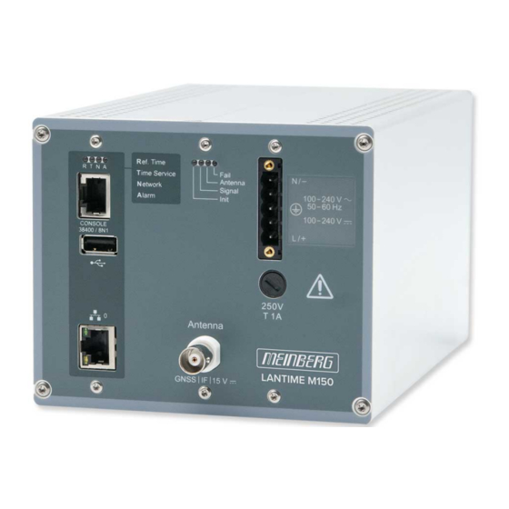
Page 29: M150 - Front Connectors
10 M150 - Front Connectors 10 M150 - Front Connectors M150/GPS/AD(DC) Power Supply Options: M150/... AC/DC power supply 90-264 V 100-250 V M150/.../DC DC power supply 20 - 60 V LANTIME Date: April 26, 2023... - Page 30 "Ref. Time" green: the reference clock (e.g. build-in GPS) provides a valid time red: the reference clock does not provide a valid time "Time Service" green: NTP is synchronized to the reference clock, e.g. GPS red: NTP is not synchronized or switched to the "local clock"...
-
Page 31: Ac/Dc Power Connector
10 M150 - Front Connectors 10.1 AC/DC Power Connector Connector Type: 5-Pin MSTB Pin Assignment: 1: N/- 2: not connected 3: PE (Protective Earth) 4: not connected 5: L/+ Power Supply Specifications ——————————————————————————– Rated Voltage Range: 100–240 V 100–240 V Max. -
Page 32: Dc Power Connector
10.2 DC Power Connector Connector: 5pin DFK Pin Assignment: 1: not connected 2: V 3: PE (Protective Earth) 4: V 5: not connected Input Parameter —————————————————————————— Nominal voltage range: = 48 V Maximum voltage range: = 20 - 60 V Nominal current: = 0.63 A Output Parameter... -
Page 33: Fuse
10 M150 - Front Connectors 10.3 Fuse The fuse protects the device from overload and short circuits, and thus prevents damage to the installed power supply. This fuse is accessible from the front panel and can be replaced. Technical Specifications ————————————————————... -
Page 34: Status Leds Of The Receiver
10.4 Status LEDs of the Receiver Init Blue: Clock is initializing Green: Oscillator is "warmed up" (disciplined) Signal Green: Geolocation complete Antenna Red: Antenna has a fault, is not correctly connected, or is short-circuited Green: Antenna is connected and clock is synchronized Fail Red: The clock is in free-run mode and is running... -
Page 35: Terminal
10 M150 - Front Connectors 10.5 Terminal A serial terminal connection (for certain device mod- els) can be established using the "CONSOLE" RJ45 connector of the LANTIME. The PC can be connected to the time server using a CAB-CONSOLE-RJ45 ca- TXD_OUT ble. -
Page 36: Antenna Input: Gps Reference Clock
10.7 Antenna Input: GPS Reference Clock Antenna Input: Antenna Circuit, Galvanically Isolated N-Norm Dielectric Strength: 1000 V Type-N Receiver Type: 12-Channel GPS Receiver Signal Support: L1 C/A (1575.42 MHz) Mixing Frequency: 10 MHz Reference Clock to Antenna (GPS Converter): Intermediate 35.4 MHz Frequency: Antenna... -
Page 37: 1000Base-T Gigabit Network Port
10 M150 - Front Connectors 10.8 1000BASE-T Gigabit Network Port Signal 1000BASE-T Data transmission rate: 10/100/1000 Mbit/s Connection Type: 8P8C (RJ45) Cable: Copper twisted pair Duplex Modes: Half/Full/Autonegotiaton LANTIME Date: April 26, 2023... -
Page 38: Technical Appendix
11 Technical Appendix 11.1 Technical Specifications: LANTIME Chassis Chassis: Extruded housing constructed to be mounted on DIN rail Chassis Material: Aluminum ——————————————————————————- Temperature Range Operation: 0 to +50 C (32 to 122 F) Storage: -20 to +70 C (-4 to 158 F) ——————————————————————————- Relative Humidity Operation:... - Page 39 11 Technical Appendix Chassis Dimensions LANTIME Date: April 26, 2023...
- Page 40 External Ground Terminal on the Chassis This terminal must be wired to a bonding busbar (grounding busbar). The terminal is located on the side of the chassis with the power supply unit. The parts required to establish this connection—not including the grounding conductor cable itself—are included with the product as shipped.
-
Page 41: Technical Specifications: Gps Antenna And Accessories
11 Technical Appendix 11.2 Technical Specifications: GPS Antenna and Accessories Voltage Draw: 15 V Casing Material: Injection-Molded ABS (via antenna cable) Polymer Casing for Outdoor Use Power Consumption: 100 mA (via antenna cable) IP Rating: IP66 Reception Frequency: 1575.42 MHz Humidity: 95 % Bandwidth:... -
Page 42: Technical Specifications: Mbg S-Pro Surge Protector
11.3 Technical Specifications: MBG S-PRO Surge Protector Adapter plug with replaceable gas discharge tube for coaxial signal connections. Connector Type: Type-N connector female/female. The MBG S-PRO set includes a surge protector (Phoenix CN-UB-280DC-BB), a pre-assembled coaxial cable, and a mounting bracket. The coaxial cable surge protector must be installed on the antenna line. - Page 43 11 Technical Appendix Max. Discharge Current: (8/20) s Maximum (Core-Shield) 20 kA Rated Pulse Current: (10/1000) s (Core-Shield) 100 A Impulse Discharge Current: (10/350) s, Peak Value I 2.5 kA Output Voltage Limit: At 1 kV/ s (Core-Earth) spike 900 V At 1 kV/ s (Core-Earth) spike 900 V Response Time:...
-
Page 44: Mbg S-Pro: Physical Dimensions
11.4 Technical Specifications: Antenna Cable The table below shows which coaxial cable types and lengths are supported by Meinberg for each of the receiver types. If you need to purchase a replacement cable at any time, please refer to this table to ensure that you select cable with suitable cutoff... -
Page 45: How Satellite Navigation Works
11 Technical Appendix 11.5 How Satellite Navigation Works The use of a receiver for location tracking and time synchronization relies on the ability to measure the satellite- to-receiver propagation delay as precisely as possible. It is necessary to have simultaneous reception from four satellites so that the receiver can determine its relative spatial position in three dimensions (x, y, z) and mea- sure the deviation of its clock against the system clock. -
Page 46: Rohs Conformity
12 RoHS Conformity Conformity with EU Directive 2011/65/EU (RoHS) We hereby declare that this product is compliant with the European Union Directive 2011/65/EU and its delegated directive 2015/863/EU “Restrictions of Haz- ardous Substances in Electrical and Electronic Equip- ment”. We warrant that our electrical and electronic products sold in the EU do not contain lead, cadmium, mer- cury, hexavalent chromium, polybrominated biphenyls (PBBs), polybrominated diphenyl ethers (PBDEs),... -
Page 47: Declaration Of Conformity For Operation In The European Union
13 Declaration of Conformity for Operation in the European Union 13 Declaration of Conformity for Operation in the European Union EU-Konformitätserklärung Doc ID: LANTIME M150/GPS-April 26, 2023 Hersteller Meinberg Funkuhren GmbH & Co. KG Manufacturer Lange Wand 9, D-31812 Bad Pyrmont erklärt in alleiniger Verantwortung, dass das Produkt,... - Page 48 EU-Declaration of Conformity Doc ID: LANTIME M150/GPS-April 26, 2023 Diese EU-Konformitätserklärung umfasst alle nachfolgend aufgeführten Gerätekonfigurationen: This EU Declaration of Conformity further covers all the device configurations listed below: LANTIME M150/GPS M150/GPS/DC Bad Pyrmont, den April 26, 2023 Date: April 26, 2023...
-
Page 49: Declaration Of Conformity For Operation In The United Kingdom
14 Declaration of Conformity for Operation in the United Kingdom 14 Declaration of Conformity for Operation in the United Kingdom UKCA Declaration of Conformity Doc ID: LANTIME M150/GPS-April 26, 2023 Manufacturer Meinberg Funkuhren GmbH & Co. KG Lange Wand 9... - Page 50 UKCA Declaration of Conformity Doc ID: LANTIME M150/GPS-April 26, 2023 This UKCA Declaration of Conformity further covers all the device configurations listed below: LANTIME M150/GPS M150/GPS/DC Bad Pyrmont, Germany, dated April 26, 2023 Date: April 26, 2023 LANTIME...
Need help?
Do you have a question about the LANTIME M150/GPS and is the answer not in the manual?
Questions and answers