
Subscribe to Our Youtube Channel
Related Manuals for Meinberg LANTIME M150/GPS


Summary of Contents for Meinberg LANTIME M150/GPS
- Page 1 TECHNICAL REFERENCE LANTIME M150/GPS June 27, 2024 Meinberg Funkuhren GmbH & Co. KG...
-
Page 3: Table Of Contents
Table of Contents 1 Imprint 2 Copyright and Liability Exclusion 3 Presentation Conventions in this Manual Conventions for the Presentation of Critical Safety Warnings ....Secondary Symbols Used in Safety Warnings . - Page 4 Table of Contents 11.1 Technical Specifications: LANTIME Chassis ......11.2 Technical Specifications: GPSANTv2 Antenna ......11.3 Technical Specifications: MBG-S-PRO Surge Protector .
-
Page 5: Imprint
1 Imprint 1 Imprint Meinberg Funkuhren GmbH & Co. KG Lange Wand 9, 31812 Bad Pyrmont, Germany Phone: + 49 (0) 52 81 – 93 09 - 0 Fax: + 49 (0) 52 81 – 93 09 - 230 Website: https://www.meinbergglobal.com Email: info@meinberg.de... -
Page 6: Copyright And Liability Exclusion
Meinberg reserves the right to make changes of any type to this document at any time as is necessary for the purpose of improving its products and services and ensuring compliance with applicable standards, laws &... -
Page 7: Presentation Conventions In This Manual
3 Presentation Conventions in this Manual 3 Presentation Conventions in this Manual 3.1 Conventions for the Presentation of Critical Safety Warnings Warnings are indicated with the following warning boxes, using the following signal words, colors, and symbols: Caution! This signal word indicates a hazard with a low risk level. Such a notice refers to a procedure or other action that may result in minor injury if not observed or if improperly performed. -
Page 8: Secondary Symbols Used In Safety Warnings
3.2 Secondary Symbols Used in Safety Warnings Some warning boxes may feature a secondary symbol that emphasizes the defining nature of a hazard or risk. The presence of an "electrical hazard" symbol is indicative of a risk of electric shock or lightning strike. -
Page 9: Generally Applicable Symbols
3 Presentation Conventions in this Manual 3.4 Generally Applicable Symbols The following symbols and pictograms are also used in a broader context in this manual and on the product. The presence of the "ESD" symbol is indicative of a risk of product damage caused by electrostatic discharge. -
Page 10: Important Safety Information
It is the responsibility of the operator to ensure that the product is safely and properly used. Should you require additional assistance or advice on safety-related matters for your product, Meinberg’s Technical Support team will be happy to assist you at any time. Simply send a mail to techsupport@meinberg.de. -
Page 11: Product Documentation
If any of the safety information in the product documentation is unclear for you, do not continue with the set-up or operation of the device! Safety standards and regulations change on a regular basis and Meinberg updates the corresponding safety information and warnings to reflect these changes. It is therefore recommended to regularly visit the Meinberg website at https://www.meinbergglobal.com or the Meinberg Customer Portal at... -
Page 12: Safety During Installation
Never drill holes into the device to mount it! If you are experiencing difficulties with rack installation, contact Meinberg’s Technical Support team for assistance! Inspect the device housing before installation. The device housing must be free of any damage when it is installed. -
Page 13: Electrical Safety
Always pull cable connectors out at both ends before performing work on connectors! Improperly connecting or disconnecting this Meinberg system may result in electric shock, possibly resulting in injury or death! When pulling out a connector, never pull on the cable itself! Pulling on the cable may cause the plug to become detached from the connector or cause damage to the connector itself. - Page 14 5-Pin MSTB Connector 3-Pin MSTB Connector = 100 - 200 V = 90 - 250 V Illustration: Lock screws on an MSTB plug connector; in this case on a LANTIME M320 Ensure that all plug connections are secure. In particular, when using plug connectors with lock screws, ensure that the lock screws are securely tightened.
-
Page 15: Special Information For Devices With Ac Power Supply
4 Important Safety Information 4.4.1 Special Information for Devices with AC Power Supply This device is a Protection Class 1 device and may only be connected to a grounded outlet (TN system). For safe operation, the installation must be protected by a fuse rated for currents not exceeding 20 A and equipped with a residual-current circuit breaker in accordance with applicable national standards. -
Page 16: Safety When Maintaining And Cleaning The Device
If a power supply unit or module is no longer functional (for example due to a defect), it can be returned to Meinberg for repair. Some components of the device may become very hot during operation. Do not touch these surfaces! If maintenance work is to be performed on the device and the device housing is still hot, switch off... -
Page 17: Important Product Information
5 Important Product Information 5 Important Product Information 5.1 CE Marking This product bears the CE mark as is required to introduce the product into the EU Single Market. The use of this mark is a declaration that the product is compliant with all requirements of the EU directives effective and applicable as at the time of manufacture of the product. -
Page 18: Maintenance And Modifications
5.4 Maintenance and Modifications Important! Before performing any maintenance work on or authorized modification to your Meinberg system, we recommend making a backup of any stored configuration data (e.g., to a USB flash drive from the Web Interface). 5.4.1 Replacing the Battery Your device’s clock module is fitted with a lithium battery (type CR2032) that is used to locally storage almanac... -
Page 19: Replacing The Fuse
Meinberg recommends keeping a spare fuse to hand at all times to ensure that a triggering of the integrated fuse does not disrupt the operation of your system for any longer than absolutely necessary. Ensure that it is of the proper type, and that it has the appropriate current and voltage ratings and blow curve. -
Page 20: Disposal
It can be returned to Meinberg for disposal. Any transportation expenses for returning this product (at end-of- life) must be covered by the end user, while Meinberg will bear the costs for the waste disposal itself. If you wish for Meinberg to handle disposal for you, please get in touch with us. Otherwise, please use the return and collection systems provided within your country to ensure that your device is disposed of in a compliant fashion to protect the environment and conserve valuable resources. -
Page 21: Introduction To Your Lantime Server
Thank you for purchasing your new LANTIME time server. Meinberg’s LANTIME Series M servers rely on proven, robust, and resilient technology to provide an ab- solute and highly precise NTP time reference in a variety of chassis types, whether for rack installation, DIN rail mounting, or desktop use. -
Page 22: Installing A Gps Antenna
7.1 Selecting the Antenna Location There are essentially two ways a compatible Meinberg GPS Antenna (such as a GPSANTv2) can be installed using the accessories included: 1. Mounted on a pole 2. - Page 23 55 south parallels (satellite orbits). Information: Problems may arise with the synchronization of your Meinberg time server if these conditions are not met, as four satellites must be located to calculate the exact position. LANTIME Date: June 27, 2024...
-
Page 24: Installation Of The Antenna
7.2 Installation of the Antenna Please read the following safety information carefully before installing the antenna and ensure that it is ob- served during the installation. Danger! Do not mount the antenna without an effective fall arrester! Danger of death from falling! •... - Page 25 7 Installing a GPS Antenna Mount the Meinberg GPS Antenna (as shown in Fig. 3) at a distance of at least 50 cm to other antennas using the mounting kit provided, either onto a vertical pole of no more than 60 mm diameter or directly onto a wall.
-
Page 26: Antenna Cable
Meinberg provides suitable cable types with its antennas and these are ordered together with the antenna to match the length you need from your antenna to your Meinberg reference clock. The route to be covered for your antenna installation should be determined and the appropriate cable type selected accordingly before confirming your order. - Page 27 7 Installing a GPS Antenna Laying the Antenna Cable When laying the antenna cable, ensure that the specified maximum cable length is not exceeded. This length will depend on the selected cable type and its attenuation factor. If the specified maximum length is exceeded, correct transmission of the synchronization data and thus proper synchronization of the reference clock can no longer be guaranteed.
- Page 28 Compensating for Signal Propagation Time The propagation of the signal from the antenna to the receiver (reference clock) can incur a certain delay. This delay can be compensated for in the LANTIME Web Interface. To do this, log into the Web Interface of your LANTIME system and proceed as follows: Open the menu "Clock"...
-
Page 29: Surge Protection And Grounding
Please refer to the standards regarding antenna installations (e.g., DIN EN 60728-11) for more information. However, in order to preserve the safety of the building and to protect your Meinberg system, Meinberg recomends the use of the MBG-S-PRO surge protector, which is addressed in more detail later in this chapter. -
Page 30: Electrical Bonding
Electrical Bonding Electrical bonding is the connection of all metallic, electrically conductive elements of the antenna instal- lation in order to limit the risk of dangerous voltages for people and connected devices. To this end, the following elements should be connected and integrated into a bonding system: •... - Page 31 7 Installing a GPS Antenna The following drawings illustrate how a Meinberg GPS Antenna can be installed in accordance with the above conditions on a pole (e.g., antenna pole) or building roof. Antenna Installation without Insulated Lightning Rod System α...
- Page 32 Antenna Installation with Insulated Lightning Rod System α Fig. 6: Roof Installation Meinberg GPS Antenna Lightning Rod Lightning Rod Conductor Antenna Cable Bonding Conductor Bonding Bar Foundation Electrode Safety Zone Date: June 27, 2024 LANTIME...
-
Page 33: Installation Conditions
7 Installing a GPS Antenna Optional MBG S-PRO Surge Protector Information: The surge protector and suitable coaxial cable are not included as standard with a Meinberg GPS Antenna, but can be ordered as an optional accessory. Construction The MBG-S-PRO is a surge protector (Phoenix CN-UB-280DC-BB) for coaxial connections. It is patched directly into the antenna line and consists of a replaceable gas discharge tube that redirects the energy from the cable shielding to the ground potential when ignited. -
Page 34: Installation And Connection
Meinberg system in order to prevent destructive potential differences. Connect the coaxial cable from the antenna to one of the surge protector connectors, then connect the other surge protector connector to the coaxial cable leading to the Meinberg reference clock. Caution! -
Page 35: Connecting Your Lantime System
8 Connecting Your LANTIME System 8 Connecting Your LANTIME System Important! • Please ensure that you have read and understood the safety information at the start of this manual before you connect your LANTIME system, and that you perform the procedure in the order listed here. -
Page 36: Configuring Your Lantime System For Your Network
(8N1), with terminal emulation set to VT100. PCs without a serial interface can be connected using a suitable serial-to-USB converter. Once a connection has been established, the login prompt should be displayed: Welcome to Meinberg LANTIME login: _ Default Benutzer: root Default Password: timeserver Note: It may be necessary to press ENTER twice after each entry. -
Page 37: Ipv6 Network Configuration
9 Configuring your LANTIME System for Your Network Once the Wizard has been started, the following introduction message will be displayed: Entering y will launch the configuration process and allow all necessary settings to be made: You can then confirm your settings. IPv6 Network Configuration Once you have completed the network configuration process for IPv4 addressing, you can access the LAN- TIME Web Interface via a web browser of your choice. -
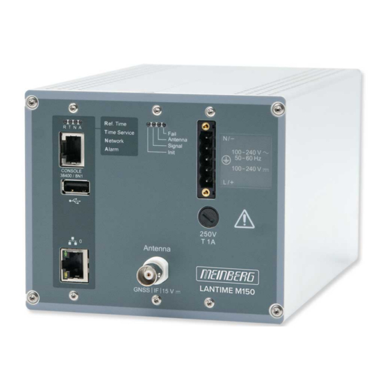
Page 38: Lantime M150 Front Connectors
10 LANTIME M150 Front Connectors M150/GPS/AD(DC) Power Supply Options: M150/... AC/DC Power Supply 90–264 V 100–250 V M150/.../DC DC Power Supply 20–60 V Date: June 27, 2024 LANTIME... - Page 39 10 LANTIME M150 Front Connectors "Ref. Time" Green: The reference clock (i.e., the integrated GPS) is providing a valid reference time. Red: The reference clock is not providing a valid reference time. "Time Service" Green: NTP is synchronized with the reference clock e.g., the integrated GPS.
-
Page 40: Ac/Dc Power Connector
10.1 AC/DC Power Connector Connector Type: 5-Pin MSTB Pin Assignment: 1: N/- 2: Not Connected 3: PE (Protective Earth) 4: Not Connected 5: L/+ Input Specifications ——————————————————————————– Nominal Voltage Range: 100 – 240 V 100 – 240 V Rated Voltage Range: 90 –... -
Page 41: Dc Power Connector
10 LANTIME M150 Front Connectors 10.2 DC Power Connector Connector Type: 5-Pin MSTB Pin Assignment: 1: Not Connected 2: V 3: PE (Protective Earth) 4: V 5: Not Connected Input Specifications —————————————————————————— Nominal Voltage Range: = 48 V Rated Voltage Range: = 20 –... -
Page 42: Fuse
10.3 Fuse The fuse provides protection against voltage surges and short circuits and limits the risk of damage to the integrated power supply. The fuse is accessible externally and can be replaced if necessary. Technical Specifications ————————————————————— Rated Voltage: 250 V Trigger Delay: Timelag Rated Current:... -
Page 43: Receiver Status Leds
10 LANTIME M150 Front Connectors 10.4 Receiver Status LEDs Init Blue: GNSS receiver is initializing Green: Oscillator is adjusted (’warmed up’) Signal Green: Geolocation completed Antenna Red: Not synchronized, no antenna connected, or short circuit on antenna cable Green: Antenna connected and clock synchronized. Fail Red: Not synchronized... -
Page 44: Usb Port
10.6 USB Port All M-series LANTIME devices have a USB interface that allow a USB storage medium such as a flash drive to be connected. This storage medium can be used for the following tasks: • locking the keys on the local control panel to prevent unauthorized access •... -
Page 45: Antenna Input: Gps Reference Clock
10 LANTIME M150 Front Connectors 10.7 Antenna Input: GPS Reference Clock Receiver Type: 12-Channel GPS Receiver Signal Support: GPS: L1 C/A (1575.42 MHz) Mixing Frequency: 10 MHz (Reference Clock to Antenna) Intermediate Frequency: Antenna 35.4 MHz (Antenna to Reference Clock) GNSS | IF | 15 V 1) These frequencies are transferred via the antenna cable... -
Page 46: 1000Base-T Gigabit Network Port
10.8 1000BASE-T Gigabit Network Port Signal 1000BASE-T Data Transmission 10/100/1000 Mbit/s Rate: Connector Type: 8P8C (RJ45) Cable Type: Copper, Twisted Pair Duplex Modes: Half/Full/Autonegotiation Date: June 27, 2024 LANTIME... -
Page 47: Technical Appendix
11 Technical Appendix 11 Technical Appendix 11.1 Technical Specifications: LANTIME Chassis Housing Type: DIN Rail Mounted Chassis Chassis Material: Aluminum ——————————————————————————- Temperature Range Operation: 0 C to 50 C (32 F to 122 F) Storage: –20 C to 70 C (–4 F to 158 F) ——————————————————————————- Supported Relative Humidity Operation:... - Page 48 LANTIME M150 Chassis Dimensions Date: June 27, 2024 LANTIME...
- Page 49 11 Technical Appendix External Ground Conductor Terminal on Chassis This terminal must be connected to an equipotential bonding bar ("grounding bar"). The connection is located below the top-hat rail clip on the rear of the device. Please note that the parts required to affix the grounding cable are not supplied with the product.
-
Page 50: Technical Specifications: Gpsantv2 Antenna
11.2 Technical Specifications: GPSANTv2 Antenna Physical Dimensions: Date: June 27, 2024 LANTIME... -
Page 51: Specifications
11 Technical Appendix Specifications Power Supply: 15 V, approx. 100 mA (provided via antenna cable) Reception Frequency: 1575.42 MHz (GPS L1/Galileo E1 Band) Bandwidth: 9 MHz Frequencies: Mixing Frequency: 10 MHz Intermediate Frequency: 35.4 MHz Element Gain: Typically 5.0 dBic at zenith Polarization: Right-Hand Circular Polarization Axial Ratio:... -
Page 52: Technical Specifications: Mbg-S-Pro Surge Protector
11.3 Technical Specifications: MBG-S-PRO Surge Protector The MBG-S-PRO is a surge protector (Phoenix CN-UB-280DC-BB) for coaxial connections. It is patched directly into the antenna line and consists of a replaceable gas discharge tube that redirects the energy from the cable shielding to the ground potential when ignited. Connect the MBG-S-PRO using a ground conductor cable that is as short as possible. -
Page 53: How Satellite Navigation Works
11 Technical Appendix 11.4 How Satellite Navigation Works The use of a receiver for location tracking and time synchronization relies on the ability to measure the satellite- to-receiver propagation delay as precisely as possible. It is necessary to have simultaneous reception from at least four satellites so that the receiver can determine its relative spatial position in three dimensions (x, y, z) and measure the deviation of its clock against the system clock. -
Page 54: Satellite Systems
Satellite Systems GPS was installed by the United States Department of Defense (US DoD) and operates at two performance levels: the Standard Positioning Service, or SPS, and the Precise Positioning Service, or PPS. The structure of the messages transmitted by the SPS has been openly published and reception is provided for public use. The timing and navigation data of the more precise PPS is encrypted and is thus only accessible to certain (usually military) users. -
Page 55: Rohs Conformity
12 RoHS Conformity 12 RoHS Conformity Conformity with EU Directive 2011/65/EU (RoHS) We hereby declare that this product is compliant with the European Union Directive 2011/65/EU and its delegated directive 2015/863/EU "Restrictions of Haz- ardous Substances in Electrical and Electronic Equip- ment"... -
Page 56: Declaration Of Conformity For Operation In The European Union
13 Declaration of Conformity for Operation in the European Union Konformitätserklärung für den Einsatz in der Europäischen Union Doc ID: LANTIME M150/GPS-June 27, 2024 Hersteller Meinberg Funkuhren GmbH & Co. KG Manufacturer Lange Wand 9, D-31812 Bad Pyrmont erklärt in alleiniger Verantwortung, dass das Produkt,... -
Page 57: Eu-Konformitätserklärung
13 Declaration of Conformity for Operation in the European Union EU-Konformitätserklärung Doc ID: LANTIME M150/GPS-June 27, 2024 Diese EU-Konformitätserklärung umfasst alle nachfolgend aufgeführten Gerätekonfigurationen: This EU Declaration of Conformity further covers all the device configurations listed below: LANTIME M150/GPS M150/GPS/DC... -
Page 58: Declaration Of Conformity For Operation In The United Kingdom
14 Declaration of Conformity for Operation in the United Kingdom UKCA Declaration of Conformity Doc ID: LANTIME M150/GPS-June 27, 2024 Manufacturer Meinberg Funkuhren GmbH & Co. KG Lange Wand 9 31812 Bad Pyrmont Germany declares that the product Product Designation... - Page 59 14 Declaration of Conformity for Operation in the United Kingdom UKCA Declaration of Conformity Doc ID: LANTIME M150/GPS-June 27, 2024 This UKCA Declaration of Conformity further covers all the device configurations listed below: LANTIME M150/GPS M150/GPS/DC Bad Pyrmont, Germany, dated June 27, 2024...
Need help?
Do you have a question about the LANTIME M150/GPS and is the answer not in the manual?
Questions and answers