Table of Contents
Advertisement
Quick Links
Advertisement
Table of Contents

Related Manuals for Meinberg M900


Summary of Contents for Meinberg M900
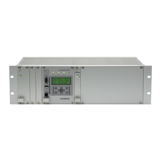
- Page 1 Technical Information Operating Instructions M900 GPS/PZF Redundant/SHS...
- Page 2 Contact Information Meinberg Funkuhren GmbH & Co. KG Lange Wand 9 D-31812 Bad Pyrmont Telephone: +49 (0) 52 81 / 9309-0 Telefax: +49 (0) 52 81 / 9309-30 Internet: http://www.meinberg.de E-Mail: info@meinberg.de Bad Pyrmont, 4. September 2009...
-
Page 3: Table Of Contents
Table of Contents Quick Start........................9 Network Timeserver with redundant time base............11 Redundant Mode....................11 SHS Mode......................12 The Modular System LANTIME.................13 Supported Network Services................14 Additional Features and Options................. 15 User Interface....................... 15 Options.........................15 Why to use a Network Timeserver..............16 Network Time Protocol (NTP).................. - Page 4 Root Menu......................31 Menu: Reference Time.....................33 Menu: Info GPS....................33 GPS Status & Version..................34 GPS Receiver Position..................34 GPS Satellite Constellation..................35 Menu: Setup GPS....................35 Set Antenna Cable Length................... 35 Set GPS Receiver Simulation Mode..............36 Menu: Init GPS....................36 Initiate Cold Boot of GPS Receiver..............36 Initiate Warm Boot of GPS Receiver..............37 Init Receiver Position...................37 Init Receiver Time....................
- Page 5 Menu: Setup IPv4 Parameter................56 Menu: Setup IPv6 Parameter................57 Menu Link Mode....................57 Menu: Network Services..................58 Menu: System...................... 58 Menu: Time Zone....................58 The LANTIME configuration interfaces..............60 The WEB interface...................... 61 Configuration: Main Menu..................62 Configuration: Ethernet................... 63 Network interface specific configuration..............65 IPv4 addresses and DHCP...................
- Page 6 Statistical Information..................95 Configuration: Manual.....................96 The Command Line Interface..................98 CLI Ethernet......................99 CLI Notification.....................102 Alarm events...................... 102 E-mail messages....................103 Windows Popup Messages................103 SNMP-TRAP messages..................104 VP100/NET wall mount display................104 NTP Client Monitoring..................105 CLI Security......................106 Password......................106 SSH Secure Shell Login..................106 Generate SSL Certificate for HTTPS ..............107 NTP keys and certificates..................
- Page 7 AM - Sine Wave Output..................147 PWM DC Output....................147 Technical Data....................147 Time Strings......................148 Format of the Meinberg Standard Time String..........148 Format of the GPS Capture String..............149 Format of the SAT-Time String.................150 Format of the Uni Erlangen String (NTP) ............151 Format of the NMEA 0183 String (RMC)............153...
- Page 8 Global Option File....................162 Third party software....................163 Operating System GNU/Linux................163 Samba.........................163 Network Time Protocol Version 4 (NTP)............164 mini_httpd......................164 GNU General Public License (GPL)..............165 Reference....................... 169...
-
Page 9: Quick Start
Quick Start When booting the system the following message will be displayed while dots will be counted up in the lower line:. Starting up Please wait..Main Menu will be displayed with some important status informations after booting has finished: GPS:SYN PZF:SYN NTP:SYN SHS:0ms... - Page 10 ->FallbackMode<- Timelimits For first time installation enter TCP/IP address, netmask and default gateway. To get an overview of the current configuration press F2 from main menu. Press F2 again to enter SETUP configuration page. Please ask your administrator for propper TCP/IP configuration: Global Cfg.
-
Page 11: Network Timeserver With Redundant Time Base
IRIG time code receiver can be integrated as an internal reference as well as a combination of these references (hybrid system). External references are also possible. The LANTIME/M900-GPS-PZF is a set of equipment composed of a satellite controlled clock GPS170, a PZF receiver, a single-board computer with integrated network board and a power supply, all installed in a metal 19"... -
Page 12: Shs Mode
12:00:00 Secure Hybrid System with Strongly Verificated Reference Time Meinberg LANTIME devices are Stratum-1 time servers which provide a high- accuracy reference time to TCP/IP networks via the Network Time Protocol (NTP). The main difference between the LANTIME models is the primary time source from which a device derives its reference time. -
Page 13: The Modular System Lantime
The Modular System LANTIME LANTIME is a set of equipment composed of a satellite controlled clock GPS170, a DCF77 long wave receiver, a single-board computer SBC LX800 500 MHz with integrated network card, and a power supply unit, all installed in a metal desktop case and ready to operate. -
Page 14: Supported Network Services
The installation of LANTIME is very easy for the system/network administrator. The network address, the netmask and the default gateway have to be configured from the front panel of LANTIME. The network address or the equivalent name of LANTIME has to be shown to all NTP clients in the TCP/IP network. As well as NTP the Linux system also supports a number of further network protocols: HTTP(S), FTP, SSH and Telnet. -
Page 15: Additional Features And Options
Additional Features and Options - external NTP timeserver - free configuration of NTP: thereby MD5 authentication and access control via address & mask restriction - extended menu guidance for configuration and monitoring via Telnet, SSH or serial terminal interface - optional up to 3 RJ45/10/100 Mbit Ethernet interfaces - extended HTTP statistic support with long-term graphic and access statistic to - alarm messages can be displayed on external large display VP100/20/NET - USB memory stick slot for extended functionality: software update, transfer of... -
Page 16: Why To Use A Network Timeserver
Why to use a Network Timeserver A network timeserver should be used if accurate time is essential for undisturbed operation. It is possible to synchronize computers in a network using Public Domain Time servers over the Internet, but there are good reasons not to use them: - The possibility to send notification via e-mail or SNMP-Trap to an administrator in the event of any synchronisation failure. -
Page 17: Ntp Target
"http://www.meinberg.de/english/sw/ntp.htm". GPS satellite controlled clock A Meinberg GPS170 satellite controlled radio clock is used as a reference time base. The satellite receiver clock GPS170 has been designed to provide extremely precise time to its user. The clock has been developed for applications where conventional radio controlled clocks can not meet the growing requirements in precision. - Page 18 The high precision orbit parameters of a satellite are called ephemeris parameters whereas a reduced precision subset of the ephemeris parameters is called a satellite’s almanac. While ephemeris parameters must be evaluated to compute the receiver’s position and clock offset, almanac parameters are used to check which satellites are in view from a given receiver position at a given time.
-
Page 19: Gps170 Features
GPS170 Features The integrated GPS170 satellite receiver is connected to the antenna/converter unit by a 50 coaxial cable (refer to "Mounting the Antenna"). Feeding the antenna/converter occurs DC insulated via the antenna cable. Optionally an antenna splitter for up to four receivers connected to one antenna is available. The navigation messages sent by the GPS satellites are decoded by the GPS170´s microprocessor in order to track the GPS system time with an accuracy of better than 250 ns or 100 ns (depending on the oscillator type of the unit). -
Page 20: Mounting The Gps Antenna
Mounting the GPS Antenna The GPS satellites are not stationary but circle round the globe in a period of about 12 hours. They can only be received if no building is in the line-of-sight from the antenna to the satellite, so the antenna/converter unit must be installed in a location from which as much of the sky as possible can be seen. -
Page 21: Assembly With Cn-Ub/E
Assembly with CN-UB/E... -
Page 22: General Information Dcf77 Pzf
General information DCF77 PZF The German long wave transmitter DCF77 started continuous operation in 1970. The introduction of time codes in 1973 build the basic for developing modern radio remote clocks. The carrier frequency of 77.5 kHz is amplitude modulated with time marks each second. -
Page 23: Features Of Pzf5Xx
Features of PZF5xx The PZF5xx is a high precision receive module for the DCF77-signal build in euro card size (100 mm x 160 mm). The micro controller of the system correlates its receiver-PZF with the incoming pseudo random sequence and decodes the time information of the DCF-telegram simultaneously. -
Page 24: Antenna
Antenna The PZF5xx operates with a ferrite antenna which is damped to match the bandwidth needed for the correlation reception. Assembly of antenna The antenna has to be mounted as exactly as possible. Turning it out of the main receive direction will result in less accurate time frames. The antenna must be placed in longitudinal direction to the DCF-transmitter (Frankfurt). -
Page 25: Precision Time Protocol (Ptp) / Ieee1588V2
Precision Time Protocol (PTP) / IEEE1588v2 PTP/IEEE1588 is a time synchronization protocol that offers sub-microsecond accuracy over a standard ethernet connection. This level of accuracy can be reached by adding a so-called hardware time stamping unit to the network ports that are used for PTP time synchronization. -
Page 26: General Information
General Information The eurocard TSU-V2 acts as a standalone single board computer including network interface card (10/100MBit) with integrated Time Stamp Unit for obtaining time stamps in IEEE1588 (PTPv2) compatible networks. In conjunction with a single board computer and a reference time source (PTP master only) the module is capable of building a PTP Master or Slave system: The Time Stamp Unit, integrated in a FPGA (Field Programmable Gate Array, programmable logic device), checks the data traffic on the MII-interface between the... -
Page 27: Functionality In Master Systems
Functionality in Master Systems After power up, the module accepts the absolute time information (PTP seconds) of a reference time source (GPS controlled clock) once only and the PTP nanoseconds are set to zero. If the oscillator frequency of the reference time source has reached it‘s nominal value, resetting of the nanoseconds is repeated. -
Page 28: Booting The Gps Receiver
Booting the GPS receiver If both, the antenna and the power supply, have been connected the system is ready to operate. About 2 minutes after power-up the receiver’s oscillator has warmed up and operates with the required accuracy. If the receiver finds valid almanac and ephemeris data in its battery buffered memory and the receiver’s position has not changed significantly since its last operation the receiver can find out which satellites are in view now. -
Page 29: Booting The Single Board Computer
Booting the Single Board Computer The LINUX operating system is loaded from a packed file on the flash disk of the single board computer to a RAM disk. All files of the flash disk are stored in the RAM disk after booting. Because of that it is guaranteed that the file system is in a defined condition after restart. -
Page 30: Configuration User Interface
Configuration User Interface There are several ways to configure the LANTIME parameters: Command Line Interface (CLI) via TELNET Command Line Interface via SSH Command Line Interface via serial terminal in front panel (38400/8N1/VT100) HTTP Interface Secure HTTP Interface (HTTPS) Front panel LCD Interface SNMP Management To put LANTIME into operation for the first time an IP address is entered via the front panel keys and LC display (refer to: DHCP IPv4 or AUTOCONF IPv6). -
Page 31: The Menus In Detail
Current time and date of the timeserver with the name of the time zone (NTP uses UTC time zone) will be monitored in the bottom line. If the "IGNORE LOCK" option is enabled an "*" will be shown behind the time. LANTIME M900 Time Network... - Page 32 If the symbol „F1“ will be shown in the upper right corner a help page can be displayed when pressing the „F1“ button. When pressing „F1“ from main menu a short description for menu navigation will be displayed: select different main menus.
-
Page 33: Menu: Reference Time
Menu: Reference Time The reference time menu and all its sub menus will manage all status information and parameters of the reference clock (GPS170 receiver). ->Ref. Time <- ->Ref. Time 1<- Time Service Ref. Time 2 Network System To enter the sub menus press the „OK“ or right arrow button:. Menu: Info GPS GPS170 SYNC... -
Page 34: Gps Status & Version
GPS Status & Version GPS170 SYNC Info GPS GPS170 v2.03 >Status&Version< SN: 000000000000 GPS Position OCXO HQ GPS Satellites This page will monitor the current state („SYNC“ or „ASYNC!“). The next line will reflect the version number of the GPS170 and the oscillator type. In the bottom line the serial number of the GPS170 will be shown. -
Page 35: Gps Satellite Constellation
GPS Satellite Constellation The SV constellation menu gives an overview of the current satellites (SVs) in view. The display shows the number of satellites with an elevation of 5° or more (In view), the number of satellites that can be used for navigation (Good) and the selected set of satellites which are used to update the receiver position (Sel). -
Page 36: Set Gps Receiver Simulation Mode
Set GPS Receiver Simulation Mode Enabling this menu lets the user run the LANTIME without antenna. Normally the NTPD loses synchronization with the GPS when the antenna is disconnected or the GPS did not receive enough satellites (red FAIL LED is turned on). When IGNORE LOCK is enabled the status information from the GPS is fixed to SYNC. -
Page 37: Initiate Warm Boot Of Gps Receiver
Initiate Warm Boot of GPS Receiver This menu lets the user force the receiver into the Boot Mode. This may be necessary when the satellite data in the memory are too old or the receiver position has changed by some hundred kilometers since last operation. Synchronization time may be reduced significantly. -
Page 38: Menu: Setup Gps Outputs
Menu: Setup GPS Outputs >Enable Outputs< ENABLE OUTPUTS Synth: always Serial Outputs Serial: always IRIG Output Pulses: always Pulse Outputs Serial Outputs Enable Outputs ->Setup COM 0 <- >Serial Outputs< Setup COM 1 IRIG Output Time Zone Pulse Outputs IRIG Output Enable Outputs Serial Outputs Code:... -
Page 39: Setup Serial Outputs
This topic is used to select one of several different types of serial time strings or the capture string for each serial port. The following time strings can be selected. All time strings are described in the appendix at the end of this documentation. Meinberg Standard String GPS Capture String SAT String UNI-Erlangen String... -
Page 40: Setup Time Zone
Setup Time Zone The time zone of the GPS receiver can be set up. These parameters will affect the serial output lines and the time code (IRIG) outputs. The internal time zone of the timeserver and the time of NTP will always be UTC. The time monitored in the main menu will be the time of the NTP. -
Page 41: Menu Time Code Irig (Output)
Menu TIME CODE IRIG (Output) This menu lets the user select the time code to be generated by GPS-TC. Most IRIG-Codes do not carry any time zone information, hence UTC is selected for output by default. If desired, the clocks local time can be output by selecting "TIME: LOCAL". -
Page 42: Programmable Pulse (Option)
Programmable pulse (Option) At the male connector type VG64 there are optionally three programmable TTL outputs (Prog Pulse 1-3), which are arbitrarily programmable. SETUP POUT X This menu is used for configuration of the pulse outputs. There are three pulse outputs available (POUT 1-3). -
Page 43: Timer Mode
Timer mode POUT1 TIMER1 out. activ: low T. ON: 10:50:00 T. OFF: 11:00:00 POUT1 TIMER2 out activ: low T. ON: 13:00:00 T. OFF: 14:00:00 POUT1 TIMER3 out activ: low T. ON: 23:45:00 T. OFF: 09:30:00 If Timer mode is selected, a window as shown above is displayed. The switching plan is assigned per day. -
Page 44: Cyclic Mode
Cyclic mode Cyclic mode is used for generating periodically repeated pulses. POUT1 CYCLIC: out activ: low T. : 00:00:02 L. : 00.10 sec The value in field 'Time' determines the time between two consecutive pulses (2 sec in example above). This cycle time must be entered as hours, minutes and seconds. The pulse train is synchronized at 0:00 o'clock local time, so the first pulse of a day always occurs at midnight. -
Page 45: Menu: Pzf Reference Time
Menu: PZF Reference Time The Reference Clock menu and all its sub menus will manage all status information and parameters of the reference clock. Ref. Time 1 ->Info <- ->Ref. Time 2 <- Setup PZF Serial Outp. For entering the sub menus press the „OK“ or right arrow button. Info PZF ->Info <-... -
Page 46: Setup Pzf
This message “State:row” indicates that the pseudo-random sequence is read into the internal RAM for one second and the system tries to achieve a coarse synchronization. This procedure starts after power-up or worse reception for more than ten seconds. If the coarse synchronization was successful, the receiver enters the state of fine- correlation. -
Page 47: Setup Pzf
COM: 9600 baud, 7E2, once per second Info COM0: 9600 7E2 Setup PZF Mode/Str. Type: ->Serial Outp.<- per second Meinberg Standa The type of time string is „Standard Meinberg“. Time strings are described in the appendix at the end of this documentation. -
Page 49: Menu: Time Service
Menu: Time Service The Time Service page is used to set up the additional time service parameters for needed for a more specific configuration of the NTP and PTP IEEE1588 subsystem. Ref. Time ->NTP Settings<- ->Time Service<- 2nd receiver Network System To enter the following sub menu press the „OK“... -
Page 50: Menu: Stratum Of Local Clock
Menu: Stratum of local clock The local clock is only chosen as the NTP time reference after the GPS clock lost its synchronisation. The stratum level of this local clock is set to 12, this ensures that clients recognise the switchover to the local clock and are able to eventually take further actions. -
Page 51: Menü: 2Nd Receiver
Menü: 2 Receiver Der M300 can be used in redundant mode or in SHS (Secure Hybrid System) mode. In redundant mode the internal NTPD will choose one of the both reference clocks depend on the reachability and jitter. In SHS mode the difference between GPS and PZF will be calculated and if the limit will be reached the internal NTPD will be stopped. -
Page 52: Menu: Ptp Ieee 1588
Menu: PTP IEEE 1588 The Precision Time Protocol (PTP) IEEE1588 is an optional network card with a special hardware time stamping unit to realize the high precision timing in the range of nanoseconds via Ethernet network. -> PTP V1 <- PTP V2 Menu: PTP V1 This menu reflect the main parameters:... -
Page 53: Menu: Ptp V2
PTPv1 TSU cards is that the PTPv1 TSU cards are passive. The PTP software stack is running on the main CPU of the M900. The PTPv2 TSU cards have their own CPU and its own operating system. The PTPv2 software is running on its own processor. - Page 54 With the sub menu “TSU 1 Setup” some PTP specific and network specific parameters can be set up. Domain Number: 0 SyncRate[2^x]: 1 Is Slave only: 0 Protocol: UDP The PTPv2 software stack uses only one Multicast address (224.0.1.129). The Domain Number is a fix number between 0 and 3.
-
Page 55: Menu: Network
Menu: Network Ref. Time Time Service ->Network <- System ->Global Cfg.<- Interfaces Services ->Device Names<- Network LED ->Hostname<- Domainname Nameserver Syslogserver Global Cfg. ->Interfaces <- Services >IPv4 Parameter< IPv6 Parameter Link Mode Global Cfg. Interfaces ->Services <- > SSH:x< IPv6:x TELN:x HTTP:x SNMP:... -
Page 56: Menu: Global Configuration
Menu: Global Configuration ->Global Cfg.<- > Device Names < > Hostname < Interfaces Network LED Domainname Services Nameserver Syslogserver In this sub menu you can change the global network settings like host and domain name, nameserver and syslog server. Further name- or syslog servers can be set up via HTTP interface or CLI Setup. -
Page 57: Menu: Network Interfaces
Menu: Network Interfaces Global Cfg. >IPv4 Parameter< ->Interfaces <- IPv6 Parameter Services Link Mode Menu: Setup IPv4 Parameter >ETH0 Address< >IPv4 Parameter< ETH0 Netmask IPv6 Parameter Def. Gateway Link Mode There is a separate configuration submenu for every physical network interface. If there is no DHCP client mode activated a static IP address for each interface can be entered. -
Page 58: Menu: Setup Ipv6 Parameter
Menu: Setup IPv6 Parameter The IPV6 parameter can be configured via the front panel display for the first ethernet port (ETH0) only. Additionally IPV6 configuration can be done via network connection with TELNET, SSH or the WEB interface. You can specify up to three IPv6 addresses for your LANTIME timeserver. Additionally you can switch off the IPv6 autoconf feature. -
Page 59: Menu: Network Services
Menu: Network Services Global Cfg. > SSH:x< IPv6:x Interfaces TELN:x HTTP:x ->Services <- SNMP: NETB: FTP: HTTPS:x The possible network protocols and access methods can be configured. After pressing the OK button you can enable/disable SSH, TELNET, SNMP, FTP, IPV6, HTTP, HTTPS and NETBIOS by using the UP/DOWN Keys and navigate through the list with the LEFT/RIGHT keys. - Page 60 ->Set Timezone<- > Time Zone < DL Sav ON Restart NTP DL Sav OFF Reboot System Factory Reset This menu lets the user enter the names of the local time zone with daylight saving disabled and enabled, together with the zones´ time offsets from UTC. These parameters are used to convert UTC to local time, e.g.
-
Page 61: The Lantime Configuration Interfaces
The LANTIME configuration interfaces The LANTIME offers three different options for configuration and status management: Web interface, Command Line Interface Setup and SNMP. In order to use the SNMP features of your LANTIME, you need special software like management systems or SNMP clients. In order to use the web interface, all you need is a web browser (LANTIME supports a broad range of browsers). -
Page 62: The Web Interface
The WEB interface Connect to the web interface by entering the following address into the address field of your web browser: http://198.168.10.10 (You need to replace 198.168.10.10 with the IP address of your LANTIME). If you want to use an encrypted connection, replace the http:// with https://... -
Page 63: Configuration: Main Menu
Configuration: Main Menu After entering the right password, the main menu page shows up. This page contains an overview of the most important configuration and status parameters for the system. The start page gives a short overview of the most important configuration parameters and the runtime statistics of the unit. -
Page 64: Configuration: Ethernet
Configuration: Ethernet... - Page 65 In the network configuration all parameters related to the network interfaces can be changed. In the first section you can change the hostname and domain name. You can also specify two nameserver and two SYSLOG server. In the nameserver and syslog server fields you may enter an IPv4 or IPv6 address (the syslog servers can be specified as a hostname, too).
-
Page 66: Network Interface Specific Configuration
Network interface specific configuration The interface specific parameters can be found in the Interface section. If your LANTIME is equipped with only one network interface, you will find only one sub section (Interface 0). Otherwise you see a sub section for each installed Ethernet port. Here, the parameters for the network port can be changed. -
Page 67: High Availability Bonding
Examples: "::" is the address, which simply consists of zeros "::1" is the address, which only consists of zeros and a 1 as the last bit. This is the so-called host local address of IPv6 and is the equivalent to 127.0.0.1 in the IPv4 world "fe80::0211:22FF:FE33:4455"... -
Page 68: Additional Network Configuration
Additional Network Configuration You can configure additional network parameter like special network routes or alias definitions. For this you will edit a script file which will be activated every time after the network configuration will run. Also the Samba Configuration from “/etc/samba/smb.conf“ can be edited:... -
Page 69: Configuration: Notification
Configuration: Notification... -
Page 70: Alarm Events
Alarm events On this page you can set up different notification types for a number of events. This is an important feature because of the nature of a timeserver: running unobserved in the background. If an error or problem occurs, the timeserver is able to notify an administrator by using a number of different notification types. -
Page 71: Windows Popup Messages
- A valid nameserver entry is needed - The domain part of the “From:” address has to be valid Windows Popup Messages Most Microsoft Windows operating systems provide you with a local notification tool. You can send messages via the special Windows protocol in your local network. It is not necessary to enable the NETBIOS protocol of the LANTIME in order to use this notification. -
Page 72: User Defined Alarm Scripts
run the tool without parameters, a short usage screen is shown, explaining all parameters it may understand. See appendix for a printout of this usage screen. User defined Alarm scripts You can define your own alarm script for every event by using the “Edit user defined notification script”. -
Page 73: Alarm Messages
Alarm messages You can change the alarm message text for every event by using the “Edit Messages“ button, the messages are stored in a file /mnt/flash/notification_messages on the flash disk of your timeserver. -
Page 74: Configuration: Security
Configuration: Security... -
Page 75: Password
Password On the ““Security““ page you can manage all security relevant parameters for your timeserver. In the first section “Login” the administration password can be changed, which is used for SSH, TELNET, FTP, HTTP and HTTPS access. The password is stored encrypted on the internal flash disk and can only be reset to the default value “timeserver”... -
Page 76: Ssh Secure Shell Login
SSH Secure Shell Login The SSH provides you with a secure shell access to your timeserver. The connection is encrypted, so no readable passwords are transmitted over your network. The actual LANTIME version supports SSH1 and SSH2 over IPv4 and IPv6. In order to use this feature, you have to enable the SSHD subsystem and a security key has to be generated on the timeserver by using the “Generate SSH key”... -
Page 77: Generate Ssl Certificate For Https
Generate SSL Certificate for HTTPS HTTPS is the standard for encrypted transmission of data between web browser and web server. It relies on X.509 certificates and asymmetric crypto procedures. The timeserver uses these certificates to authenticate itself to the client (web browser). The first time a web browser connects to the HTTPS web server of your LANTIME, you are asked to accept the certificate of the web server. -
Page 78: Ntp Keys And Certificates
NTP keys and certificates The fourth and fifth section of the “Security“ page allow you to create the needed crypto keys and certificates for secure NTP operation (please see NTP authentication below). The function “Generate new NTP public key“ is creating a new self-signed certificate for the timeserver, which is automatically marked as “trusted“. -
Page 79: Configuration: Ntp
Configuration: NTP The NTP configuration page is used to set up the additional NTP parameters needed for a more specific configuration of the NTP subsystem. The default configuration of the timeserver consists of a local clock, which represents the hardware clock of your LANTIME system and the GPS reference clock. The local clock is only chosen as the NTP time reference after the GPS clock lost its synchronisation. - Page 80 available by using the ATOM driver of the NTP subsystem, which is directly interpreting the PPS (pulse per second) of the GPS reference clock. The default configuration looks like this: lantime # NTP.CONF for GPS167 with UNI ERLANGEN server 127.127.1.0 # local clock fudge 127.127.1.0 stratum 12...
- Page 81 The NTP Trusttime will specify the time how long the NTP will trust the reference time if this is not synchronized (free running). This time will be set in seconds or minutes or hours. The value 0 will be select the default value for the specific reference clock.
-
Page 82: Ntp Authentication
NTP Authentication NTP version 2 and version 3 support an authentication method using symmetric keys. If a packet is sent by the NTPD while using this authentication mode, every packet is provided with a 32 bit key ID and a cryptographic 64/128 bit checksum of the packet. - Page 83 The ntp.keys file mentioned above holds a list of all keys and their respective ID known by the server. This file should not be world-readable (only root should be able to look into this) and it may look like this: # ntp keys file (ntp.keys) 29233E0461ECD6AE # des key in NTP format...
-
Page 84: Ntp Autokey
NTP AUTOKEY NTP Version 4 supports symmetric keys and additionally provides the so-called AUTOKEY feature. The authentic of received time at the NTP clients is sufficiently ensured by the symmetric key technique. In order to achieve a higher security, e.g. against so-called replay attacks, it is important to change the used crypto keys from time to time. - Page 85 4 server time2.meinberg.de You find the server time.meinberg.de which is using the AUTOKEY feature, while time2.meinberg.de is used without any authentic checks. If you want to setup the LANTIME server as a trusted host, but need to use a different trusted authority, please create your own group key with this TA and include it with the web interface of your LANTIME (on page “Security Management”...
- Page 86 Example: This autokey group is formed by one Stratum-1-server (B), two Stratum-2-servers (D and E) and a number of clients (in the diagram there are 4 clients shown, c1 – c4). B is the trusted host, he holds the group key and a self-signed certificate marked as “trusted”.
-
Page 87: Configuration: Local
Configuration: Local... -
Page 88: Administrative Functions
You should use this function only, if the NTPD has been synchronized to the internal reference clock for more than one day. This is done here at Meinberg directly before shipping the LANTIME unit to our customers, so you do not need to use this function during normal operation. -
Page 89: User Management
The first usage of “Save settings” will load the configuration from flash into memory and activate it. The point “Download SNMP MIB files“ can be used to download all Meinberg specific SNMP MIB files to your workstation. They can be distributed to all SNMP management clients afterwards. -
Page 90: Administrative Information
Administrative Information The button “List all messages“ displays the SYSLOG of the LANTIME completely. In this log all subsystems create their entries, even the OS (upper case) kernel. The SYSLOG file /var/log/messages is only stored in the system’s ram disk, therefore it is lost after a power off or restart. - Page 91 Using the button ”List detailed GPS/PZF information“ gives you the possibility to check detailed GPS status information. The first parameter indicates the time and date of the last update of the shown parameters. Next you find the GPS and PZF receiver status and the NTP status, followed by the GPS position data.
-
Page 92: Software Update
If you need to update the software of your LANTIME, you need a special file from Meinberg, which can be uploaded to the LANTIME by first choosing the file on your local computer with the “Browse” button and then press “Start firmware update”. -
Page 93: Automatic Configuration Check
Automatic configuration check All parameters of the LANTIME can be checked for plausibility and all configured servers (e.g. SYSLOG servers, nameservers) are tested for reachability. All red colored values should be reviewed by the administrator. Because all configured hostnames / IP addresses of the servers are processed during the reachability tests, the whole check process may take a while. -
Page 94: Get Diagnostics Information
With the help of these informations the technical support from Meinberg can reproduce the current state of your LANTIME. It takes some time to collect all information from the LANTIME. Do not press the button again while this process is running - some web browsers will cancel the job if you press the button twice. -
Page 95: Configuration: Statistics
Configuration: Statistics... -
Page 96: Statistical Information
Statistical Information In the first section a graphical diagram shows the running synchronisation process. NTP is storing this statistical information in so-called “loopstats” files, which are used here to draw the curves. The red line is describing the offset between the internal reference clock (GPS) and the system clock. -
Page 97: Configuration: Manual
Configuration: Manual This page gives you access to the documents stored on your LANTIME, especially the manuals and your own notes. The two lists include filename, language, file type, date and size of the documents/notes. The LANTIME documents can be downloaded from here in order to read / print them on your workstation. - Page 98 If you want to add a note (you can maintain more than one note on your LANTIME), after choosing the button “add note” you have to enter a filename (without a directory path, all notes are stored in a fixed directory on the flash disk of your LANTIME) and the language of your note first.
-
Page 99: The Command Line Interface
The Command Line Interface The command line interface (CLI) can be used within a TELNET or SSH session. After login, just enter “setup” to start the CLI setup tool. The start page gives a short overview of the most important configuration parameters and the runtime statistics of the unit. -
Page 100: Cli Ethernet
CLI Ethernet In the network configuration all parameters related to the network interfaces can be changed. In the first section you can change the hostname and domain name. You can also specify two nameservers and two SYSLOG servers. In the nameserver and SYSLOG server fields you may enter an IPv4 or IPv6 address (the SYSLOG servers can be specified as a hostname, too). - Page 101 timeserver cannot be reached with IPv4. Please note that TELNET, FTP and NETBIOS cannot be used over IPv6 in this version. IPv4 and IPv6 can be used together on one LANTIME. To manage the interface specific parameters, you can enter the Ethernet Configuration Line page by using one of the ETHERNET buttons.
- Page 102 If the DHCP client has been activated, the automatically obtained parameters are shown in the appropriate fields (IPv4 address, netmask, gateway). You can specify up to three IPv6 addresses for your LANTIME timeserver. Additionally you can switch off the IPv6 AUTOCONF feature. IPv6 addresses are 128 bits in length and written as a chain of 16 bit numbers in hexadecimal notation, separated with colons.
-
Page 103: Cli Notification
CLI Notification Alarm events On this page you can set up different notification types for a number of events. This is an important feature because of the nature of a timeserver: running in the background. If an error or problem occurs, the timeserver is able to notify an administrator by using a number of different notification types. -
Page 104: E-Mail Messages
E-mail messages You can specify the e-mail address which is used as the senders address of the notification e-mail (From: address), the e-mail address of the receiver (To: address) and a SMTP smarthost, that is a mail server who is forwarding your mail to the receiver. -
Page 105: Snmp-Trap Messages
SNMP-TRAP messages Up to two SNMP trap receiver hosts can be configured in this subsection, you may use IPv4 or IPv6 addresses or specify a hostname. Additionally you have to enter a valid SNMP community string for your trap receiving community. These are mostly independent from the SNMP community strings used for status monitoring and configuration (see SNMP configuration on the “Security”... -
Page 106: Ntp Client Monitoring
NTP Client Monitoring You can monitor a group of NTP clients and supervise the time offset, the NTP stratum value and if the client is reachable or not. With the button „edit client list“ you can edit the list of clients to monitor. You can add the TCP/IP address or the hostname of the client: You can monitor the current states of the configured clients:... -
Page 107: Cli Security
CLI Security Password On the “Security“ page you can manage all security relevant parameters for your timeserver. In the first section “Login” the administration password can be changed, which is used for SSH, TELNET, FTP, HTTP and HTTPS access. The password is stored encrypted on the internal flash disk and can only be reset to the default value “timeserver”... -
Page 108: Generate Ssl Certificate For Https
If you enabled SSH, your LANTIME automatically is able to use secure file transfer with SCP or SFTP protocol. The usage of FTP as a file transfer protocol is as insecure as using TELNET for shell access. Generate SSL Certificate for HTTPS HTTPS is the standard for encrypted transmission of data between web browser and web server. -
Page 109: Cli Ntp Parameter
CLI NTP Parameter The NTP configuration page is used to set up the additional NTP parameters needed for a more specific configuration of the NTP subsystem. The default configuration of the timeserver consists of a local clock, which represents the hardware clock of your LANTIME system and the GPS reference clock. The local clock is only chosen as the NTP time reference after the GPS clock lost its synchronisation. -
Page 110: Cli Ntp Authentication
CLI NTP Authentication Please see the corresponding chapter in the web interface description. CLI NTP Autokey Please see the corresponding chapter in the web interface description. -
Page 111: Cli Local
You should use this function only, if the NTPD has been synchronized to the internal reference clock for more than one day. This is done here at Meinberg directly before shipping the LANTIME unit to our customers, so you do not need to use this function during normal operation. -
Page 112: User Management
The function “Reset to factory defaults“ is setting all configuration parameters back to default values. The regular file /mnt/flash/global_configuration will be replaced with the file /mnt/flash/factory.conf, but first a copy of the configuration is saved under /mnt/flash/global_configuration.old for backup reasons. The default password “timeserver”... - Page 113 Mar 15 13:35:17 LanGpsV4 ntpd[12948]: frequency initialized 45.212 PPM from /etc/ntp.drift Mar 15 13:38:36 LanGpsV4 lantime[417]: NTP sync to GPS Mar 15 13:38:36 LanGpsV4 lantime[417]: NTP restart Mar 15 13:45:36 LanGpsV4 proftpd[14061]: connect from 172.16.3.2 (172.16.3.2) Mar 15 14:01:11 LanGpsV4 login[15711]: invalid password for `root' on `ttyp1' from `172.16.3.45' Mar 15 14:01:17 LanGpsV4 login[15711]: root login on `ttyp1' from...
-
Page 114: Software Update
If you need to update the software of your LANTIME, you need a special file update.tgz from Meinberg, which has to be uploaded to the LANTIME by using ftp, SCP or SFTP to the root dir (/update.tgz), after the file transfer is complete, press “Start firmware update”. -
Page 115: Snmp Support
MD5 SHA1 Encryption support: By using the special Meinberg SNMP-agent all important status variables can be read with SNMP conformant client software. Where applicable, a variable is implemented as string and numeric value, for example allowing SNMP client software to use the information for drawing diagrams or monitor threshold levels. - Page 116 By using the standard MIB, no NTP get requests are allowed. Only the standard system and network parameters can be accessed (e.g. using the NET-SNMP command “snmpget”). Only by using the Meinberg MIB the change of configuration parameters is possible (the command “snmpset“ is used to alter a variable, for example).
-
Page 117: Configuration Over Snmp
Configuration over SNMP The LANTIME timeserver can be configured via several user interfaces. Besides the possibility to setup its parameters with the web interface (HTTP and/or HTTPS) and the direct shell access via Telnet or SSH, a SNMP based configuration interface is available. -
Page 118: Examples For The Usage Of The Snmp Configuration Features
MBG-SNMP-LANTIME-CFG-MIB::mbgLtCfgSyslogserver1.0 = STRING: MBG-SNMP-LANTIME-CFG-MIB::mbgLtCfgSyslogserver2.0 = STRING: [...] To alter a parameter, with net-snmp you would use the snmpset command: root@testhost:/# snmpset -v2c -r 0 -t 10 -c rwsecret timeserver.meinberg.de mbgLtCfghostname.0 string „helloworld“ MBG-SNMP-LANTIME-CFG-MIB::mbgLtCfghostname.0 = STRING: helloworld root@testhost:/# Please note that your SNMP request has to be sent with a sufficient timeout (in the above snmpset example this was achieved by using the “-t 10“... -
Page 119: Further Configuration Possibilities
Further configuration possibilities Because the timeserver uses a standard version of the net-snmp SNMP daemon (with extended features covering the timeserver-specific functions), all configuration parameters of the SNMPD can be used. The configuration file of the SNMP daemon is located at /usr/local/share/snmp after boot time, the filename is snmpd.conf. During the boot sequence, this file is created dynamically by using a template file and appending the SNMP parameters stored in the timeserver setup. - Page 120 (e.g. mail, winpopup, SYSLOG etc.). A few examples: (we are again using the snmpset command which comes with the net-snmp tools). root@testhost:/# snmpset -v2c -r 0 -t 10 -c rwsecret timeserver.meinberg.de mbgLtCmdExecute.0 int 1 MBG-SNMP-LANTIME-CMD-MIB::mbgLtCmdExecute.0 = INTEGER: Reboot(1) root@testhost:/# The command shown above is forcing the timeserver to reboot.
-
Page 121: Configuration Of The Timeserver With Snmp: Reference
LANTIME SNMP traps mbgLantime.4 mbgLtCfg LANTIME configuration variables mbgLantime.5 mbgLtCmd LANTIME control commands Further detailed information can be found in the Meinberg MIB files. Reference of LANTIME SNMP configuration variables: SNMP branch Variable Data type Description mbgLtCfgNetwork mbgLtCfghostname string... - Page 122 SNMP branch Variable Data type Description mbgLtCfgNtpServer3KEY integer Link to the key which should be used for the third NTP-server mbgLtCfgStratumLocalClock integer(0..15) Stratum-value of the internal system clock of the timeserver mbgLtCfgNTPTrustedKey integer Link to the key which should be used for the internal reference time source mbgLtCfgNTPBroadcastIP string (IPv4 or IPv6-...
- Page 123 SNMP branch Variable Data type Description mbgLtCfgNotify mbgLtCfgNotifyNTPNotSync Exactly one, none or a combination of string(combination the following notification types: email=sending an email wmail=sending a winpopup-message snmp=sending a SNMP-trap, disp=showing on wall mount display, syslog=sending a syslog-entry for the event „NTP not synchronized“ mbgLtCfgNotifyNTPStopped string (combination) (see mbgLtCfgNotifyNTPNotSync) for the event „NTP Daemon stopped“...
-
Page 124: Snmp Traps
(-p is for output to stdout, -s would use the syslog for output). The corresponding MIB files can be found on the LANTIME at /usr/local/share/snmp/mibs/ , all Meinberg specific MIB files are named “MBG-SNMP….” . These MIB files can be downloaded by using the web interface (see “Local” page, “Download MIB files”... -
Page 125: Snmp Trap Reference
SNMP Trap Reference All traps can be found under the mbgLtTraps section in the Meinberg MIB. A special trap exists for every notification event the timeserver knows. Please note that the traps are only sent if you configured the notification type “SNMP trap” for the event, otherwise no trap is generated. -
Page 126: Attachment: Technical Information
Attachment: Technical Information Skilled/Service-Personnel only: Replacing the Lithium Battery The life time of the lithium battery on the board is at least 10 years. If the need arises to replace the battery, the following should be noted: ATTENTION! There is a Danger of explosion if the lithium battery is replaced incorrectly. -
Page 127: Safety Instructions For Building-In Equipment
Safety instructions for building-in equipment This building-in equipment has been designed and tested in accordance with the requirements of Standard IEC 950 "Safety of Information Technology Equipment, including Electrical Business Equipment". During installation of the building-in equipment in an end application (i.e. rack) additional requirements in accordance with Standard IEC 950 have to be taken into account. -
Page 128: Front- / Rear Panel Connectors
Front- / Rear Panel Connectors Name Type Signal Cable Front panel TERM 9 pin SUB-D RS-232 shielded data line Network RJ-45 Ethernet shielded data line USB connector Rear panel COMx 9 pin SUB-D RS-232 shielded data line Pulses Out 9 pin SUB-D TTL via 50 shielded coaxial line Error Relay... -
Page 129: Connector Assignments
Connector Assignments pin2: TxD (Transmit Data / output) pin3: RxD (Receive Data / input) pin5: GND (Signal Ground) Pin 1: PPS (Pulse Per Second Out) Pin 3: PPM (Pulse Per Minute Out) Pin 5: GND (Signal Ground) RS232 TERMINAL To connect a serial terminal use 9 pin SUBD RS232 connector in the front panel. Via the serial terminal connection it possible to configure parameters with the command line interface. -
Page 130: Time Sync Error Relay
Time Sync Error Relay On the back panel of the device you can find a DFK connector labeled „Error“. This relay output is connected to the TTL TIME_SYNC output of the reference clock (GPS, PZF, TCR, ...). If the internal reference clock has been synchronized by its source (GPS, DCF77 or IRIG) the relay will switch to mode „NO“... -
Page 131: Technical Specifications Gps Receiver
3 asynchronous serial ports (RS-232) COM0: fixed, internal used COM1: fixed, internal used COM2+3: configurable, sending Standard Meinberg Time String (once per second or per minute) POWER REQUIREMENTS: 5 V ± 5 %, @ 700 mA PHYSICAL DIMENSION: Eurocard, 100 mm x 160 mm... -
Page 132: Oscillator Options
Oscillator options... -
Page 133: Technical Specifications Gps Antenna
Technical Specifications GPS Antenna ANTENNA: Dielectric patch antenna, 25 x 25 mm Receive frequency: 1575.42 MHz Bandwidth: 9 MHz CONVERTER: Local oscillator to converter frequency: 10 MHz First IF frequency: 35.4 MHz POWER REQUIREMENTS: 12 V ... 18 V, @ 100 mA (provided via antenna cable) CONNECTOR: Coax type N, female AMBIENT... -
Page 134: Signal Description Gps170
Signal Description GPS170 Name Function 32a+c Ground VCC in (+5 V) 1a+c +5 V supply VCC in (+12 V) 2a+c +12 V supply P_SEC out Pulse when second changes, TTL level, active high, length 200 msec P_MIN out Pulse when minute changes, TTL level, active high, length 200 msec DCF_MARK out DCF77 compatible second marks, TTL level,... -
Page 135: Rear Connector Pin Assignments Gps170
Rear Connector Pin Assignments GPS170 VCC in (+5V) VCC in (+5V) VCC in (+12V) VCC in (+12V) VDD in (TCXO/OCXO) VDD in (TCXO/OCXO) (reserved, FreqAdjust out) P_SEC out (reserved, 10 MHz in) P_MIN out /RESET in/out 100 kHz out ProgPulse0 out 1 MHz out ProgPulse1 out 10 MHz out... -
Page 136: Technical Specifications Pzf5Xx
Technical specifications PZF5xx RECEIVER: Preamplifier with two post-connected receiver channels for best aquisition and tracking of the DCF-signals. CONTROL OF RECEPTION: The DCF-signal is checked for minimum field strength by microprocessor. The result is indicated by LED. In addition, the value of the digitized field strength is displayed in menu 'FIELD'. - Page 137 ANTENNA: Ferrite antenna in plastic housing HUMIDITY: Relativ humidity 85 % max. TEMPERATURE RANGE: 0° - 60 ° Celsius POWER SUPPLY: + 5 V, approx. 330 mA...
-
Page 138: Signal Description Pzf5Xx
Signal description PZF5xx Name Function 32a+c Reference potential VCC in (+5 V) 1a+c +5 V power supply VDD in (+12 V) 2a+c +12 V power supply, reserved DCF_MARK out DCF77 Emulation, TTL level, active high pulse duration: 100 ms or 200 ms P_SEC out Pulse per second, TTL-level, active high /P_SEC out... -
Page 139: Rear Connector Pin Assignments Pzf5Xx
Rear Connector Pin Assignments PZF5xx VCC in (+5V) VCC in (+5V) VDD in (+12V) VDD in (+12V) /BOOT in DCF_MARK out reserved /P_SEC out P_SEC out /P_MIN out P_MIN out /RESET in/out 100 kHz out 77,5 kHz out 1 MHz out 155 kHz out 10 MHz out 310 kHz out... -
Page 140: Technical Specifications Lan Cpu
Technical Specifications LAN CPU Geode TM LX800 with 500 MHz PROCESSOR: MAIN MEMORY: 256 MB CACHE-MEMORY: 16 KB 2nd Level Cache FLASHDISK: 64 MB (128 MB) NETWORK CONNECTOR: 10/100 MBIT with RJ45-Jack DAVICOM DM9102AEthernet NIC Controller SERIAL - INTERFACE: Four serial RS232-Ports 16550 compatible to FIFO - RS232 9-pol. -
Page 141: Rear Connector Pin Assignments Lan Cpu
Rear Connector Pin Assignments LAN CPU VCC in (+5V) VCC in (+5V) VCC in (+5V) VCC in (+5V) VCC in (+5V) VCC in (+5V) PPS in /AFD out /STB out /ERR in /SLIN out /INIT out D5 in/out D6 in/out D7 in/out LPT1 D2 in/out... -
Page 142: Technical Specifications Power Supply Unit Puls Ap 336-505
Technical Specifications Power Supply Unit PULS AP 336-505 INPUT VOLTAGE: 105 ... 300 V DC, max. 0.7 A 85 ... 265 V AC, 47... 63 Hz, max. 1.5 A FUSE: Electronic OUTPUT VOLTAGES: Vout1: 5.15 V / 2 A Vout2: +12 V / 1 A Vout3: -12 V / 1 A... -
Page 143: Timecode (Option)
Timecode (option) Abstract The transmission of coded timing signals began to take on widespread importance in the early 1950´s. Especially the US missile and space programs were the forces behind the development of these time codes, which were used for the correlation of data. -
Page 144: Irig Standard Format
IRIG Standard Format... -
Page 145: Afnor Standard Format
AFNOR Standard Format... -
Page 146: Assignment Of Cf Segment In Ieee1344 Code
Assignment of CF Segment in IEEE1344 Code Bit No. Designation Description Position Identifier P5 Year BCD encoded 1 Year BCD encoded 2 low nibble of BCD encoded year Year BCD encoded 4 Year BCD encoded 8 empty, always zero Year BCD encoded 10 Year BCD encoded 20 high nibble of BCD encoded year Year BCD encoded 40... -
Page 147: Generated Time Codes
Generated Time Codes Besides the amplitude modulated sine wave signal, the board also provides unmodulated DC-Level Shift TTL output in parallel. Thus six time codes are available. a) B002: 100 pps, PWM DC signal, no carrier BCD time-of-year b) B122: 100 pps, AM sine wave signal, 1 kHz carrier frequency BCD time-of-year c) B003:... -
Page 148: Outputs
Outputs The module GPS167-TC provides modulated and unmodulated (DC-Level Shift) outputs. The format of the timecodes is illustrated in the diagramms "IRIG-" and "AFNOR standard-format". AM - Sine Wave Output The amplitude-modulated carrier is available at the VG-connector pin 14a. The carrier frequency depends on the code and has a value of 1 kHz (IRIG-B). -
Page 149: Time Strings
Time Strings Format of the Meinberg Standard Time String The Meinberg Standard Time String is a sequence of 32 ASCII characters starting with the STX (start-of-text) character and ending with the ETX (end-of-text) character. The format is: <STX>D:dd.mm.yy;T:w;U:hh.mm.ss;uvxy<ETX> The letters printed in italics are replaced by ASCII numbers whereas the other characters are part of the time string. -
Page 150: Format Of The Gps Capture String
Format of the GPS Capture String The Meinberg GPS Capture String is a sequence of 31 ASCII characters terminated by a CR/LF (Carriage Return/Line Feed) combination. The format is: CHx_tt.mm.jj_hh:mm:ss.fffffff<CR><LF> The letters printed in italics are replaced by ASCII numbers whereas the other characters are part of the time string. -
Page 151: Format Of The Sat-Time String
Format of the SAT-Time String The SAT-Time String is a sequence of 29 ASCII characters starting with the STX (start-of-text) character and ending with the ETX (end-of-text) character. The format <STX>dd.mm.yy/w/hh:mm:ssxxxxuv<ETX> The letters printed in italics are replaced by ASCII numbers whereas the other characters are part of the time string. -
Page 152: Format Of The Uni Erlangen String (Ntp)
Format of the Uni Erlangen String (NTP) The time string Uni Erlangen (NTP) of a GPS-clock is a sequence of 66 ASCII characters starting with the STX (start-of-text) character and ending with the ETX (end-of-text) character. The format is: <STX>tt.mm.jj; w; hh:mm:ss; voo:oo; acdfg i;bbb.bbbbn lll.lllle hhhhm<ETX> The letters printed in italics are replaced by ASCII numbers whereas the other characters are part of the time string. - Page 153 leap second insertion ‘L’ leap second is actually inserted (active only in 60th sec.) ‘ ‘ (space, 20h) no leap second is inserted bbb.bbbb latitude of receiver position in degrees leading signs are replaced by a space character (20h) latitude, the following characters are possible: ‘N’...
-
Page 154: Format Of The Nmea 0183 String (Rmc)
Format of the NMEA 0183 String (RMC) The NMEA String is a sequence of 65 ASCII characters starting with the ‘$’ character and ending with the characters CR (carriage return) and LF (line-feed). The format is: $GPRMC,hhmmss.ss,A,bbbb.bb,n,lllll.ll,e,0.0,0.0,ddmmyy,0.0,a*hh<CR><LF> The letters printed in italics are replaced by ASCII numbers or letters whereas the other characters are part of the time string. -
Page 155: Format Of The Abb Spa Time String
Format of the ABB SPA Time String The ABB SPA Time String is a sequence of 32 ASCII characters starting with the characters ">900WD" and ending with the <CR> (Carriage Return) character. The format is: >900WD:yy-mm-tt_hh.mm;ss.fff:cc<CR> The letters printed in italics are replaced by ASCII numbers whereas the other characters are part of the time string. -
Page 156: Format Of The Computime Time String
Format of the COMPUTIME Time String The COMPUTIME Time String is a sequence of 24 ASCII characters starting with the characters “T" and ending with the <LF> (Line-Feed, ASCII-Code 0Ah) character. The format is: T:jj:mm:tt:ww:hh:mm:ss<CR><LF> The letters printed in italics are replaced by ASCII numbers whereas the other characters are part of the time string. -
Page 157: Format Of The Racal Standard Time String
Format of the RACAL standard Time String The RACAL standard Time String is a sequence of 16 ASCII characters terminated by a X (58h) character and ending with the CR (Carriage Return, ASCII Code 0Dh) character. The format is: <X><G><U>yymmddhhmmss<CR> The letters printed in italics are replaced by ASCII numbers whereas the other characters are part of the time string. -
Page 158: Format Of The Sysplex-1 Time String
Format of the SYSPLEX-1 Time String The SYSPLEX1 time string is a sequence of 16 ASCII characters starting with the SOH (Start of Header) ASCII controll character character and ending with the LF (line feed, ASCII Code 0Ah) character. The format is: <SOH>ddd:hh:mm:ssq<CR><LF>... -
Page 159: Konformitätserklärung
Konformitätserklärung Declaration of Conformity Hersteller Meinberg Funkuhren GmbH & Co. KG Lange Wand 9 Manufacturer D-31812 Bad Pyrmont erklärt in alleiniger Verantwortung, dass das Produkt, declares under its sole responsibility, that the product Produktbezeichnung NTP Timeserver Product Name Lantime M900/GPS/PZF... -
Page 160: Manual Vp100/Net Display Configuration
Manual VP100/NET Display configuration send2display Version 0.1 usage: send2display -h hostname -s serialnumber [options] Valid options are: -h, --host H Uses H as the hostname of the display unit -s, --serialnumber S Uses S as the serialnumber of the display (e.g. 03A00C7F) -c, --clear M Clear message M (0-31) - Page 161 If you want the message (any type) to appear periodically, you can set the time interval with: -D, --periodday D Display message every D days -H, --periodhour H Display message every H hours -M, --periodminute M Display message every M minutes (You can combine these options.
-
Page 162: Global Configuration File
#----------------------- # Configuration File Section Configuration File Version Number :4.05 Configuration File Last Change :Mon Mar 15 07:44:21 2004 # Network Parameter Section Hostname [ASCII,50]:LanGpsV4 Domainname [ASCII,50]:py.meinberg.de IPv4 GATEWAY ..[IP]:0 IPv6 GATEWAY ..[IP]:0 Nameserver 1 [IP]: Nameserver 2... -
Page 163: Global Option File
SNMP Write Community String [ASCII,50]: SNMP Contact String [ASCII,50]:Meinberg SNMP Location String [ASCII,50]:Germany # Windows Messages Section WMail Address 1 [ASCII,50]: WMail Address 2 [ASCII,50]: # VP100 Display Section VP100 Display Address 1 [ASCII,50]: VP100 Display Sernum [ASCII,50]: VP100 Display Address 2... -
Page 164: Third Party Software
Third party software The LANTIME network timeserver is running a number of software products created and/or maintained by open source projects. A lot of people contributed to this and we explicitly want to thank everyone involved for her/his great work. The used open source software comes with its own license which we want to mention below. -
Page 165: Network Time Protocol Version 4 (Ntp)
Network Time Protocol Version 4 (NTP) The NTP project, lead by David L. Mills, can be reached in the internet at www.ntp.org. There you will find a wealthy collection of documentation and information covering all aspects of the application of NTP for time synchronization purposes. -
Page 166: Gnu General Public License (Gpl)
GNU General Public License (GPL) GNU GENERAL PUBLIC LICENSE Version 2, June 1991 Copyright (C) 1989, 1991 Free Software Foundation, Inc. 675 Mass Ave, Cambridge, MA 02139, USA Everyone is permitted to copy and distribute verbatim copies of this license document, but changing it is not allowed. Preamble The licenses for most software are designed to take away your freedom to share and change it. - Page 167 is covered only if its contents constitute a work based on the Program (independent of having been made by running the Program). Whether that is true depends on what the Program does. 1. You may copy and distribute verbatim copies of the Program's source code as you receive it, in any medium, provided that you conspicuously and appropriately publish on each copy an appropriate copyright notice and disclaimer of warranty;...
- Page 168 The source code for a work means the preferred form of the work for making modifications to it. For an executable work, complete source code means all the source code for all modules it contains, plus any associated interface definition files, plus the scripts used to control compilation and installation of the executable.
- Page 169 countries not thus excluded. In such case, this License incorporates the limitation as if written in the body of this License. 9. The Free Software Foundation may publish revised and/or new versions of the General Public License from time to time. Such new versions will be similar in spirit to the present version, but may differ in detail to address new problems or concerns.
-
Page 170: Reference
Reference [Mills88] Mills, D. L., "Network Time Protocol (Version 1) - specification and implementation", DARPA Networking Group Report RFC-1059, University of Delaware, July 1988 [Mills89] Mills, D. L., "Network Time Protocol (Version 2) - specification and implementation", DARPA Networking Group Report RFC-1119, University of Delaware, September 1989 [Mills90] Mills, D.
Need help?
Do you have a question about the M900 and is the answer not in the manual?
Questions and answers