Meinberg LANTIME M300 Technical Reference
Hide thumbs
Also See for LANTIME M300:
- Manual (141 pages) ,
- Operating instructions manual (115 pages) ,
- Technical reference (46 pages)

Related Manuals for Meinberg LANTIME M300


Summary of Contents for Meinberg LANTIME M300
- Page 1 TECHNICAL REFERENCE LANTIME M300/GPS/FDM March 1, 2022 Meinberg Funkuhren GmbH & Co. KG...
-
Page 3: Table Of Contents
3 General Information about LANTIME 4 LANTIME Chassis: Technical Specifications 5 LANTIME M300 Front Connectors 6 LANTIME M300 Rear Connectors Power Connector .......... -
Page 4: Imprint
1 Imprint 1 Imprint Meinberg Funkuhren GmbH & Co. KG Lange Wand 9, 31812 Bad Pyrmont, Germany Phone: + 49 (0) 52 81 / 93 09 - 0 Fax: + 49 (0) 52 81 / 93 09 - 230 Website: https://www.meinbergglobal.com Email: info@meinberg.de... -
Page 5: Important Safety Information
2 Important Safety Information 2.1 Important Safety Information and Safety Precautions The following safety information must be observed whenever the device is being installed or operated. Failure to observe this safety information and other special warnings or operating instructions in the product manuals constitutes improper usage and may violate safety standards and the manufacturer’s requirements. -
Page 6: Used Symbols
2 Important Safety Information 2.2 Used Symbols The following symbols and pictograms are used in this manual. Pictograms are used in particular to indicate potential hazards in all hazard categories. Symbol Beschreibung / Description IEC 60417-5031 Gleichstrom / Direct current IEC 60417-5032 Wechselstrom / Alternating current IEC 60417-5017... -
Page 7: Product Documentation
Detailed product documentation is provided on a USB flash drive delivered with the system. The manuals can also be downloaded from the Meinberg website at https://www.meinbergglobal.com, where you can enter your system name into the search box at the top of the page to find the relevant manual. Alternatively, contact Meinberg Support for further assistance. -
Page 8: Safety During Installation
2 Important Safety Information 2.4 Safety during Installation WARNING! Pre-Operation Procedures and Preparation for Use This mountable device has been designed and examined in accordance with the requirements of the standard IEC 62368-1 "Audio/Video, Information and Communication Technology Equipment - Part 1: Safety Requirements". When the mountable device is to be used as part of a larger unit (e.g., electrical enclosure), there will be additional requirements in the IEC 62368-1 standard that must be observed and complied with. - Page 9 = 90 - 250 V Faulty shielding or cabling and improperly connected plugs are a health & safety risk (risk of injury or death due to electrical shock) and may damage or even destroy your Meinberg device or other equipment.
- Page 10 2 Important Safety Information AC Power Supply DC Power Supply The device is a Protection Class 1 device and In accordance with IEC 62368-1, it must be • • may only be connected to a grounded outlet possible to disconnect the appliance from the (TN system).
-
Page 11: Connection Of Protective Earth Conductor/Grounding
2.5 Connection of Protective Earth Conductor/Grounding ATTENTION! In order to ensure that the device can be operated safely and to meet the requirements of IEC 62368-1, the device must be correctly connected to the protective earth conductor via the protective earth connection terminal. If an external earth terminal is provided on the housing, it must be connected to your bonding busbar (grounding busbar). -
Page 12: Safety During Operation
2 Important Safety Information 2.6 Safety during Operation WARNING! Avoiding Short-Circuits Protect the device against all ingress of solid objects or liquids. Ingress presents a risk of electric shock or short-circuiting! Ventilation Slots Ensure that the ventilation slots are clean and uncovered at all times. Blocked ventilation slots may cause heat to be trapped in the system, resulting in overheating. -
Page 13: Safety During Maintenance
Opening the device or individual device components in an unauthorized fashion may also expose the user to considerable risks and invalidate your warranty. Meinberg Funkuhren accepts no liability for consequences arising from such unauthorized actions. Danger from moving parts—do not touch moving parts. -
Page 14: Handling Of Batteries
The battery is used to power components such as the RAM and the reserve real-time backup clock for the reference clock. If the battery voltage drops below 3 V DC, Meinberg recommends having the battery replaced. If the battery voltage drops below the specified minimum, the following behavior may be observed in the reference clock: •... -
Page 15: Cleaning And Care
2.9 Cleaning and Care ATTENTION! Never clean the device using liquids! Water ingress is a significant safety risk for the user (e.g., electric shock). Liquids can cause irreparable damage to the electronics of the device! The ingress of liquids into the device chassis may cause short circuits in the electronic circuitry. Only clean with a soft, dry cloth. -
Page 16: Return Of Electrical And Electronic Equipment
When disposing of your old equipment, please use the national return or collection systems available to you. Alternatively, you may contact Meinberg, who will provide further assistance. The return of electronic waste may not be accepted if the device is soiled or contaminated in such a way that it potentially presents a risk to human health or safety. -
Page 17: General Information About Lantime
3 General Information about LANTIME LANTIME stands for Local Area Network Time Server. The LANTIME provides an absolute and highly precise time reference in a TCP/IP network (stratum 1 server). The time is made available to all NTP clients via the NTP protocol (Network Time Protocol) and allows easy integration of an absolute time reference into an existing network. -
Page 18: Lantime Chassis: Technical Specifications
4 LANTIME Chassis: Technical Specifications 4 LANTIME Chassis: Technical Specifications Chassis: 19" Multipac Chassis, 1U Chassis Material: Sheet Steel ——————————————————————————- Temperature Range Operation: 0–50 C (32–122 F) Storage: -20–70 C (-4–158 F) ——————————————————————————- Relative Humidity Operation: Max. 93 % (Non-Condensing) at 40 C ——————————————————————————- Maximum Altitude Operation:... - Page 19 Chassis Dimensions 483 mm 19 inch 465 mm 18.31 inch 43,6 mm 1.72 inch 31,8 mm 1.25 inch 445 mm 17.51 inch 288 mm 11.32 inch 304 mm 11.98 inch External Ground Terminal on the Chassis This terminal must be wired to a bonding busbar (grounding busbar). The terminal is located on the side of the chassis with the power supply unit.
-
Page 20: Lantime M300 Front Connectors
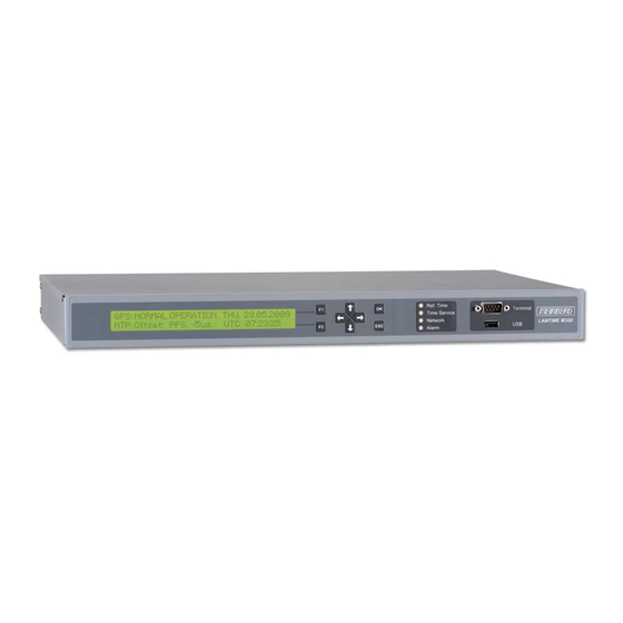
5 LANTIME M300 Front Connectors 5 LANTIME M300 Front Connectors The main menu is displayed after the device is switched on and the boot phase is completed. The main menu provides the most important status information. The top line of the display shows the operating mode of the reference clock / reference time and will nor- mally read "GPS: NORMAL OPERATION", although... - Page 21 "Ref. Time" Green: A valid time is provided by the reference clock (e.g., integrated GPS) Red: There is no valid time available from the reference clock "Time Service" Green: NTP is synchronized with the reference clock (e.g., GPS) Red: NTP is not synchronized or has switched to the "local clock"...
-
Page 22: Lantime M300 Rear Connectors
6 LANTIME M300 Rear Connectors 6 LANTIME M300 Rear Connectors LANTIME Date: March 1, 2022... -
Page 23: Power Connector
6.1 Power Connector Connector Type: IEC320 AC inlet Input Parameter ——————————————————————————– Nominal voltage Range: 100-240 V 100-240 V Maximum voltage Range: 90-264 V 100-375 V 100-240 V 100-240 V , 50-60 Hz Nominal current: 0.40 A Nominal frequency range: 50-60 Hz Maximum frequency range: 47-63 Hz Inrush current:... -
Page 24: Fdm Power Line
6 LANTIME M300 Rear Connectors 6.2 FDM Power Line Input Voltage Range: 70-270 V AC Connector: IEC-60320 C14 female Mains frequency 45-65 Hz FDM Power Line 70-270 V , 45-65 Hz WARNING! This equipment is operated at a hazardous voltage. -
Page 25: Error Relay
6.4 Error Relay A 3-pin MSTB connector labeled "Error" is located on the rear panel of the device. This 0 V ("dry") relay output is connected to the TTL TIME_SYNC output of Error the reference clock (GPS, PZF, TCR, etc.) Normally, when the internal reference clock has been synchro- nized to its source (GPS, DCF77, or IGIG), this relay will switch to "NO"... -
Page 26: Antenna Input: Gps Reference Clock
6 LANTIME M300 Rear Connectors 6.5 Antenna Input: GPS Reference Clock Antenna Input GPS: Antenna Circuit, Electrically Insulated N-Norm N-type Dielectric Strength: 1000 V Receiver Type: 12-Channel GPS C/A Code Receiver Antenna Antenna GNSS | IF | 15 V GNSS | IF | 15 V... -
Page 27: Pulse Per Second Output
6.6 Pulse per Second Output Output Signal: PPS (Pulse per Second) Signal Level: TTL 2.5 V, 50 Termination Pulse Length: 200 ms Connector Type: BNC Female PPS Out Cable: Coaxial Cable, Shielded 6.7 10 MHz Frequency Output Output Signal: 10 MHz Frequency Signal Level: TTL, 2.5 V, 50 Termination... -
Page 28: Integrated Frequence Deviation Monitor Module - Fdm
7 Integrated Frequence Deviation Monitor Module - FDM 7 Integrated Frequence Deviation Monitor Module - FDM 7.1 Overview The module FDM180 was designed to calculate and monitor the frequency and its deviation in 50/60 Hz power line networks. The preconnected reference clock supplies reference signals, which significantly define the accuracy of the measured values. -
Page 29: Display String
10 MHz oscillator clock (TTL level) Pulse per second, activ high (TTL level) Serial time string (RS-232 or USB), Meinberg Standard Time String or Uni-Erlangen Time String Mains voltage: 70 V... 270 V, 30 Hz ... 80 Hz, 2.5 VA max. -
Page 30: Installation Of The Gps Antenna
8 Installation of the GPS Antenna 8 Installation of the GPS Antenna WARNING! Do not mount the antenna without an effective fall arrester! Danger of death from falling! - Ensure that you work safely when installing antennas! - Never work without an effective fall arrester! WARNING! Do not work on the antenna system during thunderstorms! Danger of death from electric shock! - Page 31 Type-N (Male) If installed in a waterproof housing, the MBG S-PRO Type-N (Female) can be installed outdoors. However, Meinberg recommends installing the surge protector indoors—as closely to the entrance point of the antenna cable as possible—in order to minimize the risk of surge damage (such as that caused by lightning strike).
- Page 32 8 Installation of the GPS Antenna Grounding Conductor To ground the antenna cable, connect the surge to Grounding Busbar protector to a grounding busbar using a grounding Conductor of diameter approx. conductor (see illustration). 1,5 mm, attached to surge protector Once installation is complete, connect the other As short as possible end of the antenna cable to the surge protector...
- Page 33 Optional Antenna Splitter Multiple receivers can be connected to one antenna using the antenna splitter. When doing so, be aware that the total distance, comprising the cable from the antenna to the splitter, and from there to the receiver, must not exceed the maximum cable length. The splitter may be installed at any location between the surge protector and the receivers.
-
Page 34: Technical Appendix: Gps Antenna + Accessories
9 Technical Appendix: GPS Antenna + Accessories 9 Technical Appendix: GPS Antenna + Accessories Physical Dimensions: LANTIME Date: March 1, 2022... - Page 35 Specifications: Power Supply: 15 V, 100 mA (Provided via Antenna Cable) Reception Frequency: 1575.42 MHz Bandwidth: 9 MHz Frequencies: Mixed Frequency 10 MHz IF frequency: 35.4 MHz Connector: Type-N Female Form Factor: ABS Plastic Case for Outdoor Installation IP Rating: IP66 Humidity: 95 %...
-
Page 36: Antenna Cable
9 Technical Appendix: GPS Antenna + Accessories 9.1 Antenna Cable Cable Type Cable Diameter (mm/in) Attenuation at 100 MHz Max. Cable Length (m/ft) Used for Receiver Type (db)/100 m/328 ft RG58/CU 5/0.2 300/984 GPS/GNS-UC/PZF RG213 10.3/0.41 700/2297 GPS/GNS-UC H155 5.4/0.21 70/230 GNM/GNS H2010 Ultraflex... -
Page 37: Technical Specifications: Mbg S-Pro Surge Protection
9.3 Technical Specifications: MBG S-PRO Surge Protection Adapter plug with replaceable gas discharge tube for coaxial signal connections. Connector Type: Type-N connector female/female. The MBG S-PRO set includes a surge protector (Phoenix CN-UB-280DC-BB), a pre-assembled coaxial cable, and a mounting bracket. The coaxial cable surge protector must be installed on the antenna line. - Page 38 9 Technical Appendix: GPS Antenna + Accessories Max. Discharge Current: (8/20) s Maximum (Core-Shield) 20 kA Rated Pulse Current: (10/1000) s (Core-Shield) 100 A Impulse Discharge Current: (10/350) s, Peak Value I 2.5 kA Output Voltage Limit: At 1 kV/ s (Core-Earth) spike 900 V At 1 kV/ s (Core-Earth) spike 900 V...
-
Page 39: Mbg S-Pro: Physical Dimensions
9.3.1 MBG S-PRO: Physical Dimensions 15,8 9.3.2 Installation and Grounding Date: March 1, 2022 LANTIME... -
Page 40: Rohs And Weee
WEEE-compliant fashion, it must be returned to the manufacturer. Any transportation ex- penses for returning this product (at end-of-life) must be covered by the end user, while Meinberg will bear the costs for the waste disposal itself. LANTIME... -
Page 41: Declaration Of Conformity
11 Declaration of Conformity Declaration of Conformity Doc ID: LANTIME M300/GPS/FDM-July 5, 2021 Hersteller Meinberg Funkuhren GmbH & Co. KG Manufacturer Lange Wand 9, D-31812 Bad Pyrmont erklärt in alleiniger Verantwortung, dass das Produkt, declares under its sole responsibility, that the product...
Need help?
Do you have a question about the LANTIME M300 and is the answer not in the manual?
Questions and answers